

Appendix B: WireGuard VPN Configuration
APPENDIX B. WIREGUARD VPN CONFIGURATION
Section titled “APPENDIX B. WIREGUARD VPN CONFIGURATION”Main document: TR-100E User Manual
This appendix describes two WireGuard VPN configuration modes:
- static — connection parameters are specified manually to connect to a selected WireGuard peer;
- automatic — TR-100E obtains connection parameters from Overvis after it is connected to an account using a PIN code.
In both modes, TR-100E initiates communication with the remote peer independently. Configuration requires access to the TR-100E Web interface with the powerUser access level. TR-100E must have an IP connection to the remote peer; when a hostname is used, the DNS servers must be configured correctly.
B.1 Manual WireGuard Configuration
Section titled “B.1 Manual WireGuard Configuration”B.1.1 Entering Parameters
Section titled “B.1.1 Entering Parameters”For static configuration, the VPN administrator must provide the WireGuard parameters for TR-100E and configure the corresponding peer on the remote endpoint.
- Open the TR-100E Web interface and log in with the
powerUseraccess level. - Go to the Settings tab and expand the VPN-WireGuard section.
- Enable Enabled.
- Disable Automatic Connection to Overvis Server. The static configuration fields will become available for entry.
- Enter the parameters provided by the VPN administrator:
| Field | Description |
|---|---|
| Private Key | TR-100E private key in Base64 format |
| Interface Address | TR-100E address within the VPN in IPv4/CIDR format, for example 10.8.0.2/24 |
| Peer Public Key | Public key of the remote endpoint in Base64 format |
| Peer Host | DNS name or IPv4 address of the remote endpoint |
| Peer Port | UDP port of the remote endpoint, from 1 to 65535; the default value is 51820 |
| Allowed IP 1, Allowed IP 2 | Up to two networks whose traffic is routed through the peer, in IPv4/CIDR format |
| Keepalive (s) | Persistent keepalive interval from 1 to 300 s; the default value is 25 s |
The private key, interface address, peer public key, and peer host are required. Use a prefix from /1 to /32 for the interface address. Both Allowed IP fields may be left empty. If no allowed network is specified, TR-100E uses the network defined by the interface address. If one Allowed IP field is completed, the route specified in that field is used. In the current firmware version, routes with the /0 prefix are not applied; use prefixes from /1 to /32 for Allowed IP.
- Click Save in the VPN-WireGuard section. The WireGuard service will restart automatically; TR-100E does not need to be restarted.
If access to the Web interface or Modbus TCP is required through the static VPN connection, also configure the settings described in steps 5–11 of section B.2.2.
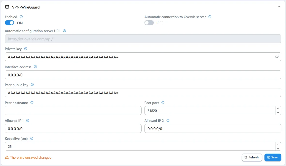
Figure B.1 – Static WireGuard configuration
B.1.2 Verifying the Connection
Section titled “B.1.2 Verifying the Connection”Go to the Service tab, select Network → VPN in the Diagnostics block, and enable Auto-refresh.
For a correctly completed static configuration, the following values are displayed:
- Service — Enabled;
- Mode — Static;
- Configuration — Ready;
- Connection — Configured, Connected, or Active.
Successful communication with the remote endpoint is confirmed by the Connected or Active state, a time in the Handshake field, and increasing RX/TX packet counters. The Invalid Configuration state means that at least one required parameter is missing: private key, interface address, peer public key, or peer host.
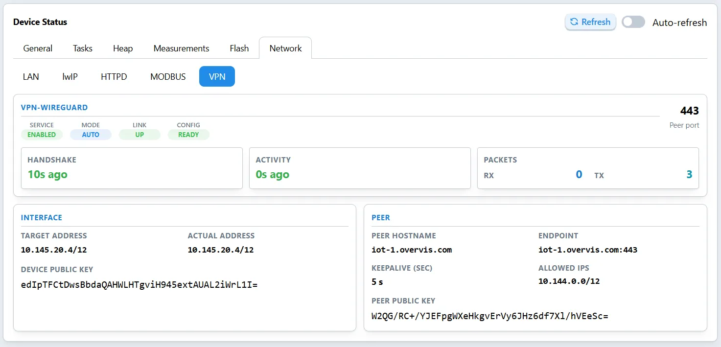
Figure B.2 – Static WireGuard connection status
If the static connection cannot be established:
- if the Invalid Configuration state is displayed, check that the private key, interface address, peer public key, and peer host are completed;
- compare all parameters against the remote peer configuration;
- when using a DNS name, check the DNS settings in Settings → Network;
- check that the peer host and UDP port are accessible from the TR-100E network;
- check that the Allowed IP routes do not overlap with the local network in an unintended way;
- make sure that the remote peer is configured to use the TR-100E key and VPN address.
B.2 Automatic Configuration via Overvis
Section titled “B.2 Automatic Configuration via Overvis”B.2.1 Verifying Identification Data
Section titled “B.2.1 Verifying Identification Data”- Open the TR-100E Web interface and log in with the
powerUseraccess level. - Go to the Service tab.
- In the Device Information block, make sure that the Device Key and Registered indicators are green and that a value is displayed in the PIN Code field. Record the PIN code (it is also printed on the device label): the code is required to connect TR-100E to the Overvis account.
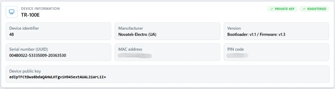
Figure B.3 – TR-100E identification data
B.2.2 Enabling Automatic Connection
Section titled “B.2.2 Enabling Automatic Connection”- Go to the Settings tab and expand the VPN-WireGuard section.
- Enable Enabled and Automatic Connection to Overvis Server.
- Leave the Automatic Configuration Server URL field empty: the address programmed by the manufacturer will then be used. Complete this field only when instructed by technical support.
- Click Save in the VPN-WireGuard section.
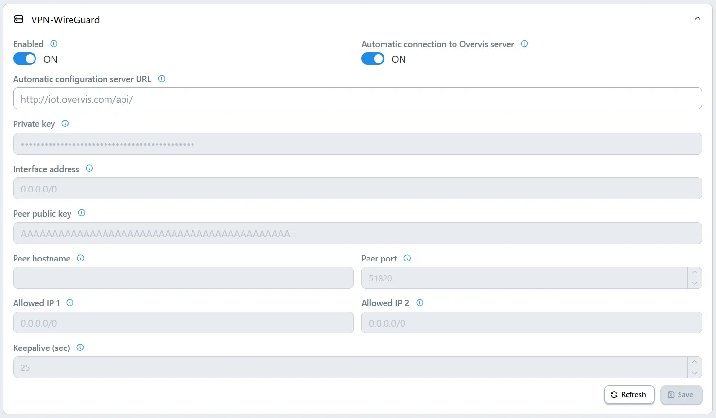
Figure B.4 – Configuring automatic connection to Overvis
- Expand the Web Server section.
- Enable Web Access via VPN and set Default Access Level via VPN to
PowerUser. - Click Save in the Web Server section.
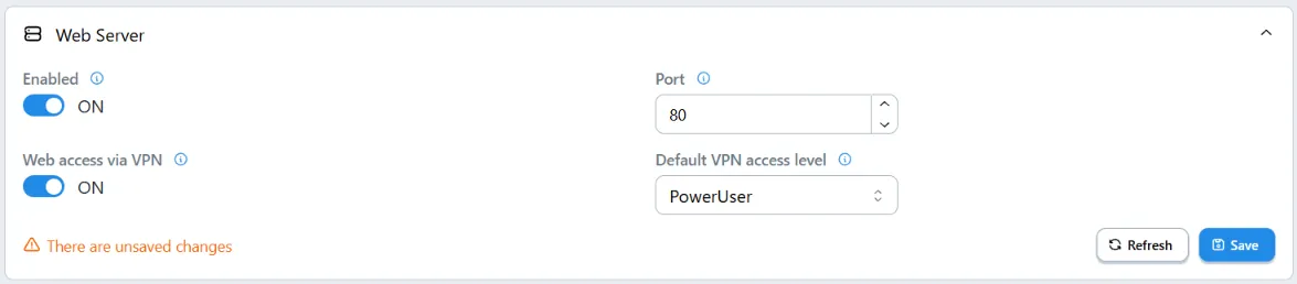
Figure B.5 – Configuring access to the Web interface via VPN
- Expand the Modbus TCP section.
- Enable Enabled and select Read and Write for Modbus Access via VPN. This access level is required so that Overvis HMI can both read and change TR-100E parameters.
- Select Write for Protection Mode. Allowing writes via VPN does not disable local Modbus protection: local clients will still require password unlocking.
- Click Save in the Modbus TCP section.
The Read and Write level grants password-free access to any Modbus TCP session accepted through the VPN interface. Use it only with a trusted WireGuard configuration. If remote parameter changes are not required, select Read Only.
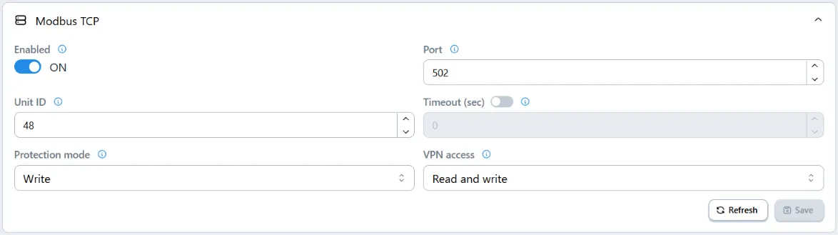
Figure B.6 – Configuring access to Modbus TCP via VPN
B.2.3 Monitoring Automatic Connection
Section titled “B.2.3 Monitoring Automatic Connection”After saving the settings, go to the Service tab, select Network → VPN in the Diagnostics block, and enable Auto-refresh. Wait for automatic configuration to finish. The following states indicate readiness for connection through Overvis:
- Service — Enabled;
- Mode — Auto;
- Configuration — Ready;
- Connection — Connected or Active;
- the Handshake field displays the time of the last communication instead of a dash.
After these states appear, proceed to connect TR-100E to the Overvis HMI account.
Figure B.7 – WireGuard ready for connection through Overvis
B.2.4 Connecting TR-100E to an Overvis HMI Account
Section titled “B.2.4 Connecting TR-100E to an Overvis HMI Account”Before continuing, make sure that TR-100E is connected to the Internet and that automatic WireGuard configuration has been completed as described in section B.2.3. Have the 8-character PIN code printed on the enclosure label ready.
- In a web browser, go to Overvis HMI.
- On the sign-in page, enter your email address in the Email field and click Send code. Enter the one-time code from the email in the field that appears. If this email address is being used for the first time, Overvis HMI will create an account after it is confirmed. No separate password is required. The code is valid for 10 minutes and can be used once. A new code can be requested after one minute; the previously issued code will then become invalid.
- When signing in for the first time, enter your name and organization name. Overvis HMI will create the first workspace from the organization name. If the workspace already exists, open it.
- Go to Manual Setup → Connections and click Create Connection.
- In the Type field, select PIN. Port 502 is used for this connection type, so the Port field is not displayed.
- In the Name field, replace New Connection with a meaningful name, such as the TR-100E installation location. Enter the code from the label in the PIN Code field and click Create.
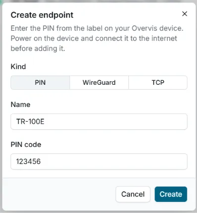
Figure B.8 – Creating a TR-100E connection using a PIN code
- Confirm device ownership: press Yes on TR-100E or enter the code shown on the device display in Overvis HMI.
- Wait for the Connection created message.
- In the Connections list, select the row that was created. On the Connection tab, make sure that the Connected state is displayed and that the Active Address field is populated. The list row must display the PIN label, manufacturer, and model code.
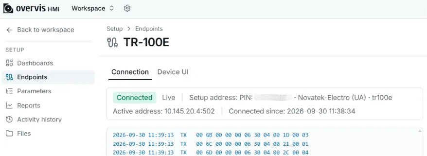
Figure B.9 – TR-100E connected to the workspace
After creation, the Type and linked device cannot be changed. If the PIN was entered incorrectly, delete the connection and create it again. This connection does not display temperatures by itself: the TR-100E parameters are added separately.
B.2.5 Adding TR-100E Parameters from a Template
Section titled “B.2.5 Adding TR-100E Parameters from a Template”After creating the connection, add the controller parameters from the Novatek-Electro TR-100E template. The connection address and port do not need to be entered again.
- In the setup menu, go to Parameters.
- Click Add and select From template….
- In the Add from template window, select the Novatek-Electro TR-100E template from the Overvis group.
- Check the Root branch name field. Change the suggested name if necessary; the field must not be left empty.
- Check the Unit ID field. The template uses the factory Modbus address of TR-100E —
48. If the controller address has been changed, enter its current value. - In the Endpoint field, select the TR-100E connection created earlier.
- Click Add. The changes do not need to be saved separately.
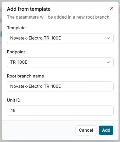
Figure B.10 – Adding TR-100E parameters from a template
After the template is applied, a new root branch containing the TR-100E parameters will appear in the Parameters tree. To check communication with the controller, select the new branch and click Read. The values received must appear to the right of the parameters. For continuous polling, enable Live.
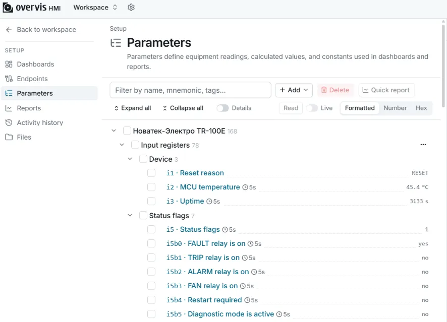
Figure B.11 – Verifying that TR-100E parameters can be read
If an error is displayed instead of values, check that the Device ID field matches the controller’s Modbus address and that the created connection has the Connected state.
Additional information is provided in the Overvis equipment connection documentation.