

Quick Start and Application Setup
This guide takes the OB-216 from an unpowered installation to a verified Modbus reading. It also shows which input, operating mode, settings, and result register belong together for each supported application.
Understand the device before wiring
Section titled “Understand the device before wiring”- Connect one input source or sensor at a time.
- Select one input operating mode in register 100.
- The input terminals used (and result register address) depend on that mode.
- The voltage and current analog outputs are two forms of the same output channel. Configure only the required output type.
- USB and RS-485 are alternative communication interfaces. With factory settings, connecting USB selects USB and disables RS-485 until the USB connection is removed.
Choose the input application
Section titled “Choose the input application”Use this table before connecting anything.
| Application | Input terminals / diagram | Register 100 / Mode of operation | Register 101 / Plugged-in digital sensor | Additional settings | Read the result at |
|---|---|---|---|---|---|
| 0–10 V sensor | IO1, Figure 2(b) | 2, meas. voltage | Optional: 104–105, 130–134 | Measured value 6; converted value 16 | |
| 0–20 mA sensor | IO1, Figure 2(a) | 3, meas. current | Optional: 104–105, 130–134 | Measured value 6; converted value 16 | |
| NTC 10KB | IO2, Figure 2(c) / sensor connection diagram | 4, NTC sensor (10 KB) | Optional: 102, 104–105 | Measured value 6 | |
| PTC 1000 | IO2, Figure 2(c) / sensor connection diagram | 5, PTC1000 sensor | Optional: 102, 104–105 | Measured value 6 | |
| PT 1000 | IO2, Figure 2(c) / sensor connection diagram | 6, PT1000 sensor | Optional: 102, 104–105 | Measured value 6 | |
| DS18B20 | Figure 3 | 8, digital sensor | 0, DS18B20 | Optional: 102–105 | Temperature 11 |
| DHT11 | Figure 3 | 8, digital sensor | 1, DHT11 | Optional: 102–105 | Temperature 11; humidity 12 |
| DHT21 / AM2301 | Figure 3 | 8, digital sensor | 2, DHT21 / AM2301 | Optional: 102–105 | Temperature 11; humidity 12 |
| DHT22 | Figure 3 | 8, digital sensor | 3, DHT22 | Optional: 102–105 | Temperature 11; humidity 12 |
| Dry-contact state | IO2, Figure 2(d) | 1, LOG input | Register 107: debounce | Status register 2:3, bit 18 | |
| Dry-contact or transistor pulses | IO2, Figure 2(e) | 0, pulse counter | Registers 106–108 | Counter 4:5 | |
| Voltage pulses | IO1, Figure 2(f) | 11, counter pul. voltage | Registers 104–106, 108 | Counter 4:5 | |
| Current pulses | IO1, Figure 2(f) | 12, counter pul. current | Registers 104–106, 108 | Counter 4:5 | |
| No sensor, remote manual output | IO1 / IO2 unconnected | 1 |
The wiring figures referenced above are reproduced in the relevant procedures below. The complete register definitions are in OB-216 settings and Additional Registers.
Initial connection and configuration
Section titled “Initial connection and configuration”What you need
Section titled “What you need”- OB-216 and the supplied microUSB cable
- Galvanically isolated 10–30 V DC power supply
- 35 mm DIN rail to mount the OB-216 on
- 0.5–3.0 mm² conductors, ferrules, and suitable tools
- The one sensor, contact, pulse source, or analog load required by the application
- Twisted-pair cable for RS-485, if used
- A Windows PC with the Control Panel OB-215/OB-216 application
- The NOVATEK USB-SERIAL driver, if Windows does not recognize the USB interface
-
Select the application
Find the required application in the table above. Record the operating-mode value for register 100, the connection figure, any additional settings, and the result register. This avoids configuring one mode while wiring another.
-
Mount and wire the OB-216
Mount the device on a 35 mm DIN rail. While all circuits are de-energized, connect the isolated 10–30 V DC supply and then connect only the sensor or signal source for the selected application.
Do not connect a digital sensor, a 0–10 V source, a 0–20 mA source, and a temperature sensor simultaneously. They are alternative uses of the input.
-
Connect the PC for initial setup
Connect the microUSB cable between the OB-216 and the PC. Install the NOVATEK USB-SERIAL driver if the interface is not detected, then start Control Panel OB-215/OB-216.
-
Apply power and establish communication
Apply 10–30 V DC power. The power indicator flashes for approximately 1.5 seconds during startup. At factory settings, the OB-216 automatically selects USB when the cable is connected.
Factory communication settings are:
Setting Factory value Modbus protocol RTU Modbus unit ID 28 Baud rate 9600 bit/s Parity / stop bits No parity, 2 stop bits Interface selection Automatic -
Set the input mode and application parameters
Set register 100 to the value selected in the application table. Configure the sensor type, thresholds, debounce, scaling, or output settings required by that procedure.
-
Save the settings
Write
18220to command register 50. The OB-216 saves the settings to flash memory, restarts, and begins operating with the new configuration. -
Verify the measurement locally
Read register 0; the expected device identifier is
28. Then read the result register listed for the application. Check the relevant status bit where applicable. Do not proceed to a controller or production network until the locally read input value is plausible. -
Move to RS-485, if required
Remove power, disconnect the USB cable, and connect the RS-485 twisted pair:
Ais the non-inverted signal andBis the inverted signal. Reapply power and configure the Modbus master to exactly match the OB-216 protocol, unit ID, baud rate, parity, and stop bits.
Application procedures
Section titled “Application procedures”0–10 V sensor (PLC / VFD output or other transmitter)
Section titled “0–10 V sensor (PLC / VFD output or other transmitter)”Use this procedure for a sensor whose output voltage is within 0–10 V.
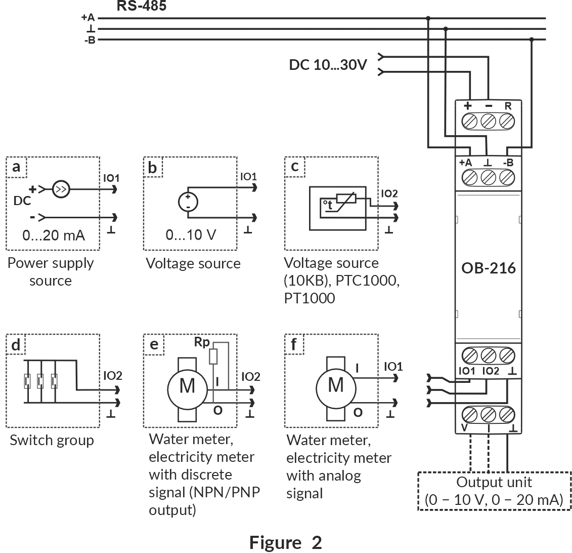
- De-energize all equipment and wire the voltage source as shown in Figure 2(b). Confirm that the source cannot exceed the OB-216 supply voltage. For correct measurement of high input values (near 10V), a 12V-24V supply is recommended.
- Set register 100 to
2(that isMode of operation=meas. voltage). - If required, set the upper threshold in register 104 and lower threshold in register 105. These affect status bits 20 and 21 only, reporting values outside these thresholds.
- Save settings by writing
18220to register 50 and allow the OB-216 to restart. - Read register 6. Voltage uses hundredths of a volt, so the value would be in
0-1000range:500means 5.00 V. - If unit conversion is required, set register 130 to
1and configure registers 131–134 with the input and converted ranges. Read the scaled result from register 16, then save the settings again.
Example — 0.5–8 V pressure sensor representing 1–25 bar: set registers 131–134 to 50, 800, 1, and 25.
Read pressure from register 16.
Use 10 and 250 if a single fractional digit is required, etc.
0–20 mA sensor or transmitter
Section titled “0–20 mA sensor or transmitter”- De-energize all equipment and wire the current loop as shown in Figure 2(a). Check the sensor documentation to determine whether an external loop supply is required. For correct measurement of high input values (near 20mA), a 12V-24V supply is recommended.
- Set register 100 to
3(that isMode of operation=meas. current). - If required, set the upper threshold in register 104 and lower threshold in register 105. These affect status bits 22 and 23 only, reporting values outside these thresholds.
- Save settings by writing
18220to register 50 and allow the OB-216 to restart. - Read register 6. Current uses hundredths of a milliampere, so the value would be in
0-2000range:450means 4.50 mA. - If unit conversion is required, set register 130 to
1, configure registers 131–134, and read the scaled result from register 16. Save the settings again.
Example — 4.5–20 mA pressure sensor representing 1–25 bar: set registers 131–134 to 450, 2000, 1, and 25.
NTC 10KB, PTC 1000, or PT 1000 analog temperature sensor
Section titled “NTC 10KB, PTC 1000, or PT 1000 analog temperature sensor”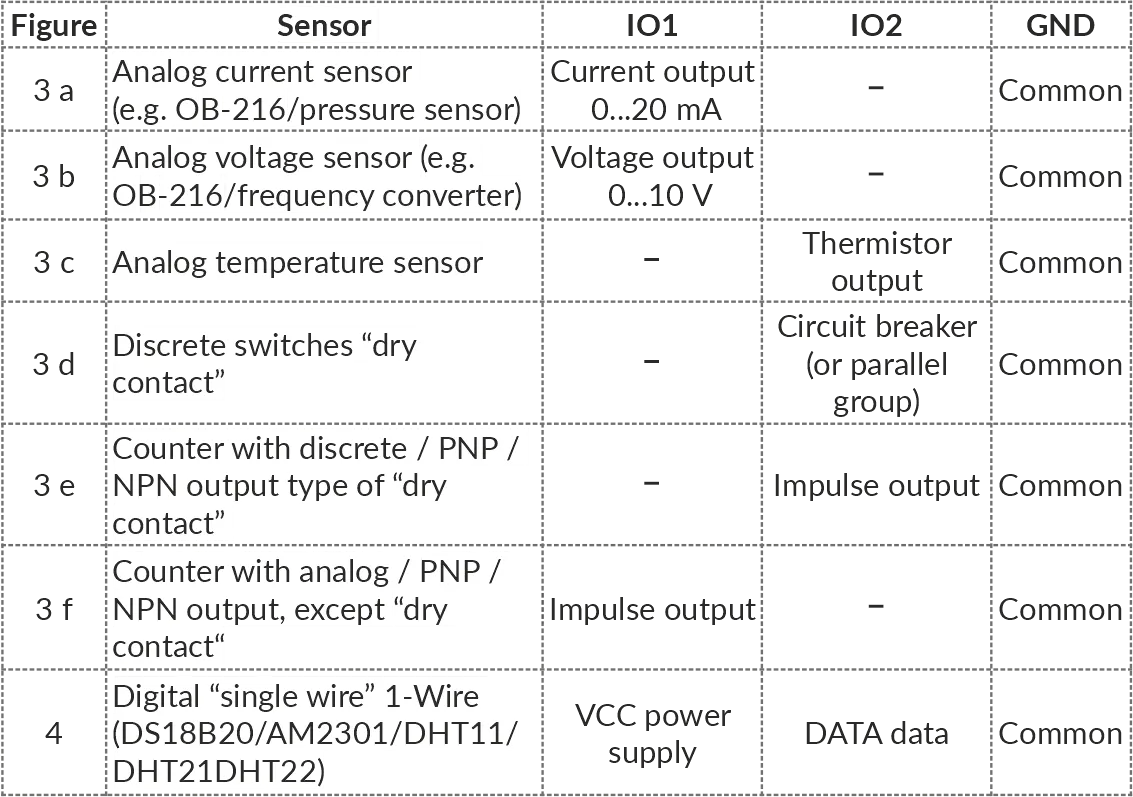
- De-energize the OB-216 and connect one analog temperature sensor using Figure 2(c) and the sensor connection diagram above.
- Set
Mode of operationregister 100 according to the sensor:4for NTC 10KB,5for PTC 1000, or6for PT 1000. - If a known
temperature correctionmust be applied, set register 102 in tenths of a degree. For example,5adds 0.5 °C and-5subtracts 0.5 °C. - Optionally set the upper and lower
temperature thresholdsin registers 104 and 105. These affect status bits 24 and 25 only, reporting values outside these thresholds. - Save settings by writing
18220to register 50 and allow the OB-216 to restart. - Read the temperature from register 6 as tenths of a degree Celsius:
234means 23.4 °C.
DS18B20 digital temperature sensor
Section titled “DS18B20 digital temperature sensor”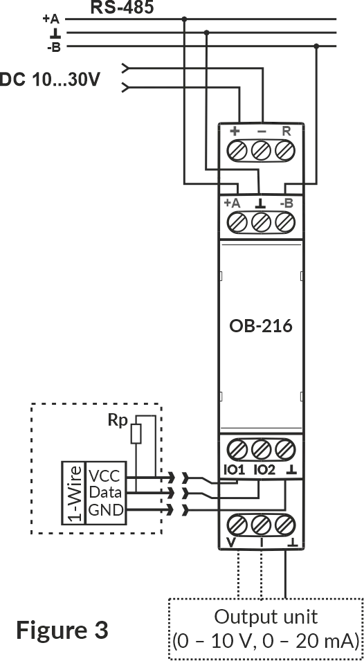
- De-energize the OB-216. Connect one DS18B20 as shown above.
- Install an external 2–5.1 kΩ pull-up resistor between the sensor
Dataline and its supply line. - Set register 100 to
8(that isMode of operation=digital sensor) and digital-sensor register 101 to0(DS18B20). - If a known
temperature correctionmust be applied, set register 102 in tenths of a degree. For example,5adds 0.5 °C and-5subtracts 0.5 °C. - Optionally set the upper and lower temperature thresholds in registers 104 and 105. These affect status bits 24 and 25 only, reporting values outside these thresholds.
- Save by writing
18220to register 50 and allow the OB-216 to restart. - Wait at least 3 seconds for a sensor poll, then read temperature from register 11 in tenths of a degree Celsius.
DHT11, DHT21 / AM2301, or DHT22 sensor
Section titled “DHT11, DHT21 / AM2301, or DHT22 sensor”- De-energize the OB-216. Connect one DHT sensor as shown in the digital-sensor wiring diagram.
- Install an external 2–5.1 kΩ pull-up resistor between the sensor
Dataline and its supply line. - Set register 100 to
8(that isMode of operation=digital sensor). - Set register 101 to
1for DHT11,2for DHT21 / AM2301, or3for DHT22. - Select with register 103 the parameter used for thresholds and automatic-output operation:
0for temperature or1for humidity. This selection does not prevent reading both available measurements. - If a known
temperature correctionmust be applied, set register 102 in tenths of a degree. For example,5adds 0.5 °C and-5subtracts 0.5 °C. - Optionally set the upper and lower thresholds in registers 104 and 105. These affect status bits 24 and 25 (for temperature selection) or 26 and 27 (for humidity selection) only, reporting values outside these thresholds.
- Save by writing
18220to register 50 and allow the OB-216 to restart. - Wait at least 3 seconds. Read temperature from register 11 in 0.1 °C and humidity from register 12 in 0.1% RH. For example, humidity value
800means 80.0% RH.
Dry-contact state input
Section titled “Dry-contact state input”- De-energize the OB-216 and connect the dry contact to
IO2as shown in Figure 2(d). - Set register 100 to
1(that isMode of operation=LOG input). - Set
Contact bounce suppressionin register 107 to a value in range 1-250 ms (if the factory value of 10 ms is unsuitable). - Save by writing
18220to register 50 and allow the OB-216 to restart. - Read the 32-bit status value from registers 2:3. Bit 18 is
1whenIO2is closed and0when it is open.
Pulse counter
Section titled “Pulse counter”Choose the pulse mode that matches the signal source:
| Pulse source | Register 100 / Mode of operation | Maximum frequency | Thresholds |
|---|---|---|---|
Dry contact / discrete signal on IO2 | 0, pulse counter | 200 Hz | Not used |
Voltage pulses on IO1 | 11, counter pul. voltage | 10 Hz | Registers 104–105 |
Current pulses on IO1 | 12, counter pul. current | 10 Hz | Registers 104–105 |
- De-energize the OB-216 and wire the source as shown in Figure 2(e) for a discrete signal or Figure 2(f) for voltage/current pulses.
- If a discrete source has a PNP output, install the external 1–5.1 kΩ resistor shown in Figure 2(e).
- Set register 100 to
0,11, or12according to the table above. - Set register 106 to
0for leading edges,1for trailing edges, or2for both edges. - For mode
0(pulse counter), set theContact bounce suppressionin register 107. - For modes
11and12, set the upper and lower detection thresholds in registers 104 and 105. These are used for pulse detection, with a valid pulse alternately crossing both thresholds. - Set register 108 to the number of input pulses represented by one counter increment. Changing register 108 clears stored counter values.
- If a non-zero starting count is required, write it to 32-bit registers 4:5.
- Save by writing
18220to register 50 and allow the OB-216 to restart. - Generate known pulses and read the 32-bit count from registers 4:5.
Analog output
Section titled “Analog output”The analog output can operate in one of two modes:
- automatically follow the selected input;
- manually set by Modbus.
| Required output | Register 150 / Work permit | Full-scale register maximum value | Additional settings |
|---|---|---|---|
| 0–10 V automatic | 1, voltage - auto | 1000 = 10.00 V | Input range 153–154, output range 155-156 |
| 0–20 mA automatic | 2, current - auto | 2000 = 20.00 mA | Input range 153–154, output range 155-156 |
| 0–10 V manual | 3, voltage - manual | 1000 = 10.00 V | Converting manual values 152, optionally conversion ranges 153–156 |
| 0–20 mA manual | 4, current - manual | 2000 = 20.00 mA | Converting manual values 152, optionally conversion ranges 153–156 |
Automatic output
Section titled “Automatic output”- First configure and verify the input application.
- Set register 150 to
1for voltage or2for current. - Set the input range in registers 153–154 and corresponding analog output range in registers 155–156. For example, to convert 4-20 mA sensor into 0-20 mA, use
400and2000for registers 153–154, and0and2000for registers 155–156. - Save by writing
18220to register 50. - Read register 17 and measure the physical output to verify the conversion.
Manual output
Section titled “Manual output”- Set register 150 to
3for voltage or4for current. - For direct values, set register 152 to
0, then write the required output to register 151. For example,500produces 5.00 V or 5.00 mA according to the selected output mode. - For scaled control, set register 152 to
1and configure the input/output ranges in registers 153–156 before writing the command value to register 151. For example, to convert 1.0-25.0 bar range into 0.5-8 V, use ranges10and250for registers 153–154, and50and800for registers 155–156. Write the pressure value in tenths of a bar to register 151. - Save the mode and conversion settings by writing
18220to register 50. - Set the register 151 (
Manual control value) and verify the output with a suitable meter before connecting the final load.
Connect the load to the current output (Figure 1, terminal 9) or voltage output (Figure 1, terminal 10), together with analog ground (terminal 8).
Verification checklist
Section titled “Verification checklist”Before considering setup complete, verify all of the following:
- Only the intended single sensor or signal source is connected to the input.
- Register 100 matches the wiring and sensor type.
- Register 101 matches the digital sensor, if used.
- The result is read from the correct register and interpreted with the correct scale.
- The value is plausible when tested at two known input points or states.
- Settings were saved by writing
18220to register 50. - Status bit 29 is
0, indicating settings are saved. - USB is disconnected before RS-485 testing in
automaticinterface mode. - The Modbus master matches unit ID, protocol, baud rate, parity, and stop bits.
- Each device on a multidrop RS-485 network has a unique unit ID.
- Only the intended single load or signal input is connected to the output.
Troubleshooting
Section titled “Troubleshooting”Q: Why is there no communication over USB?
A: Confirm the 10–30 V supply is present, install the USB-SERIAL driver, and check that register 113 is not forced to RS-485 only.
Q: Why is there no communication over RS-485?
A: Disconnect USB, check A/B polarity, and make sure the unit ID, protocol, baud rate, parity, and stop bits match. Check that register 113 is not set to USB only.
Q: Why does the reading never change?
A: Confirm that register 100 matches the wiring, verify that you are reading the correct result register, and check the sensor power and common connection.
Q: Why does the digital sensor have no valid reading?
A: Confirm that register 100 is set to 8 and register 101 matches the sensor. Install the 2–5.1 kΩ pull-up resistor and wait at least 3 seconds for a reading.
Q: Why is the analog value incorrect by a factor of 10 or 100?
A: Apply the register scaling shown in the relevant application procedure. Make sure you distinguish raw register 6 from converted register 16.
Q: Why is the threshold status unexpected?
A: For DHT sensors, check register 103. Also check the upper and lower values and their units in registers 104–105.
Q: Why do new settings disappear after power loss?
A: Write 18220 to register 50 to save the settings, then verify that status bit 29 becomes 0.
Q: Why is the pulse count too high or too low?
A: Check edge selection (register 106), debounce (register 107), pulses per increment (register 108), the frequency limit, and the thresholds for voltage or current pulse modes.
Reference
Section titled “Reference”- Operating Manual — complete specifications, installation, operation, and wiring diagrams
- OB-216 settings register table — all configurable parameters and valid ranges
- Status register — operating mode and alarm bits
- Command and additional registers — save, restart, measured values, and counters