Networks, Devices & Parameters
Overvis organizes field data in a three-level hierarchy:
| Level | Parent | Represents | Main responsibility |
|---|---|---|---|
| Network | Organization | One controller or gateway connection | Reachability and controller-level communication |
| Device | Network | One Modbus unit inside that network | Polling and write behavior for that unit |
| Parameter | Device | One readable or writable value on that device | Addressing, type conversion, storage, and writability |
This page is the reference for all three levels — what they store, how they relate to each other, and how their settings affect communication and data handling. It follows the same order as the hierarchy: networks, then devices, then parameters. For a hands-on walkthrough, see Getting Started. For connection methods and troubleshooting, see Connecting Equipment.
Hierarchy and Relationships
Section titled “Hierarchy and Relationships”Ownership
Section titled “Ownership”- Each network belongs to exactly one organization.
- Each device belongs to exactly one network.
- Each parameter belongs to exactly one device.
Identifiers
Section titled “Identifiers”Every network, device, and parameter has two identifiers:
- Internal ID — a numeric primary key used in the API and database.
- Slug — a URL-friendly string derived from the object’s name (e.g.
warehouse,temperature-controller,current-temperature). Slugs are unique within their parent scope: network slugs are unique within the organization, device slugs within their network, and parameter slugs within their device. Overvis uses slugs in page URLs.
Deletion
Section titled “Deletion”Deleting a parent deletes all its children:
- Deleting a network deletes all its devices and all parameters under those devices.
- Deleting a device deletes all its parameters.
Stored readings and event history associated with deleted parameters are also removed.
Disabling
Section titled “Disabling”Networks and devices can be disabled without deleting them. Disabling preserves all configuration and stored data but stops communication:
- A disabled network stops all reads, writes, and background polling for every device and parameter under it.
- A disabled device stops all reads, writes, and background polling for every parameter under it.
Networks and devices can be disabled by a user, by the billing system (when the organization’s balance runs out), or by a platform administrator. The disable timestamp and actor are recorded so the reason is always visible.
Re-enabling restores normal operation immediately — no reconfiguration is needed.
There is no separate enabled / disabled switch for individual parameters. Tracked and programmable control polling, history, and writes (see Behavior flags); a parameter with both flags off can still be read on demand. To stop all Modbus traffic for a device — including on-demand reads — disable the device or network.
Networks
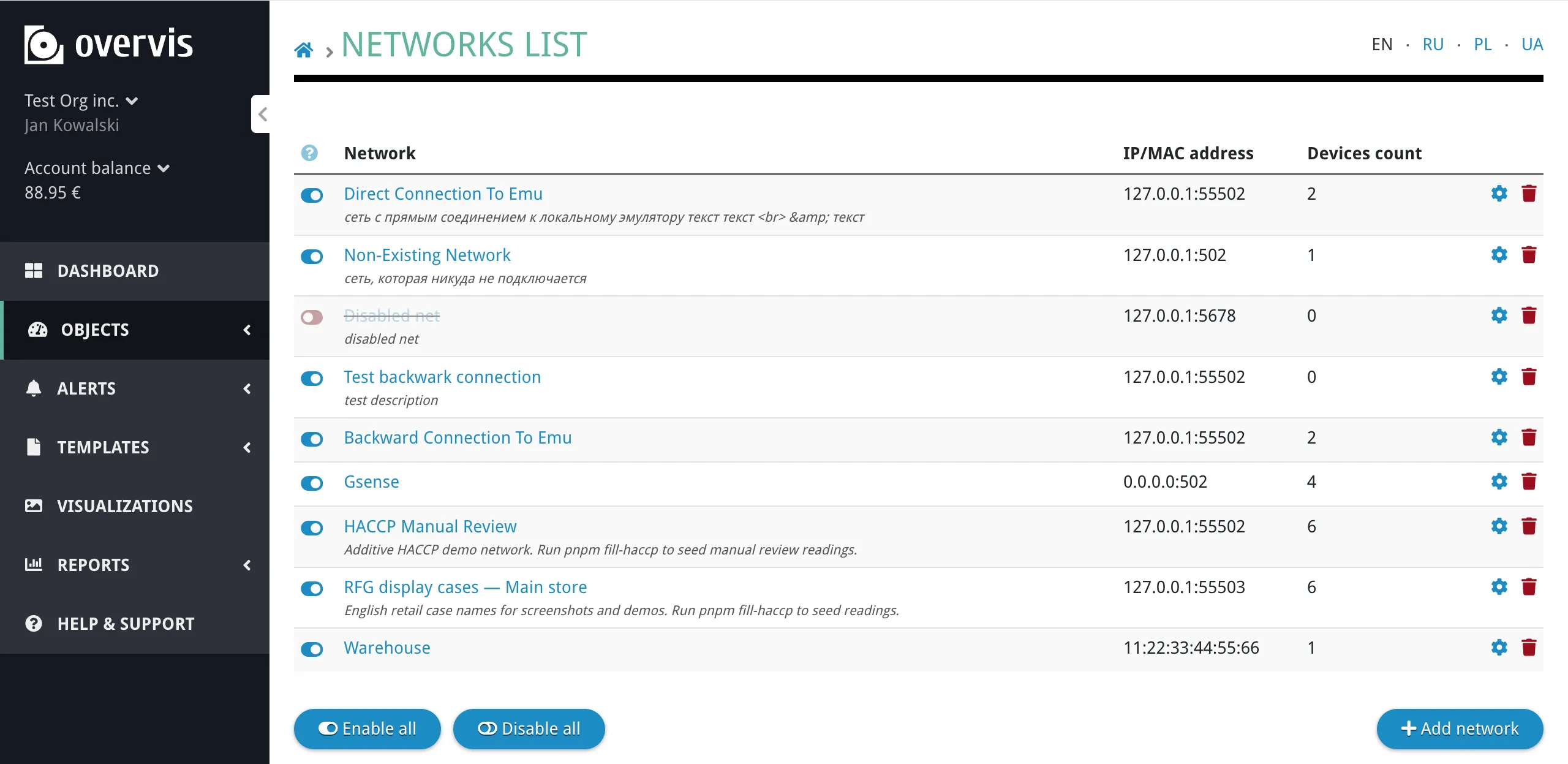
Section titled “Networks”A network represents one communication controller or gateway. Every device in the network is reached through that single connection.
Creating a Network
Section titled “Creating a Network”To create a network, go to the organization’s network list and click Add network. The create form guides you through selecting a connection method and entering connection details. For a step-by-step walkthrough of each connection method, see Connecting Equipment.
Network Settings
Section titled “Network Settings”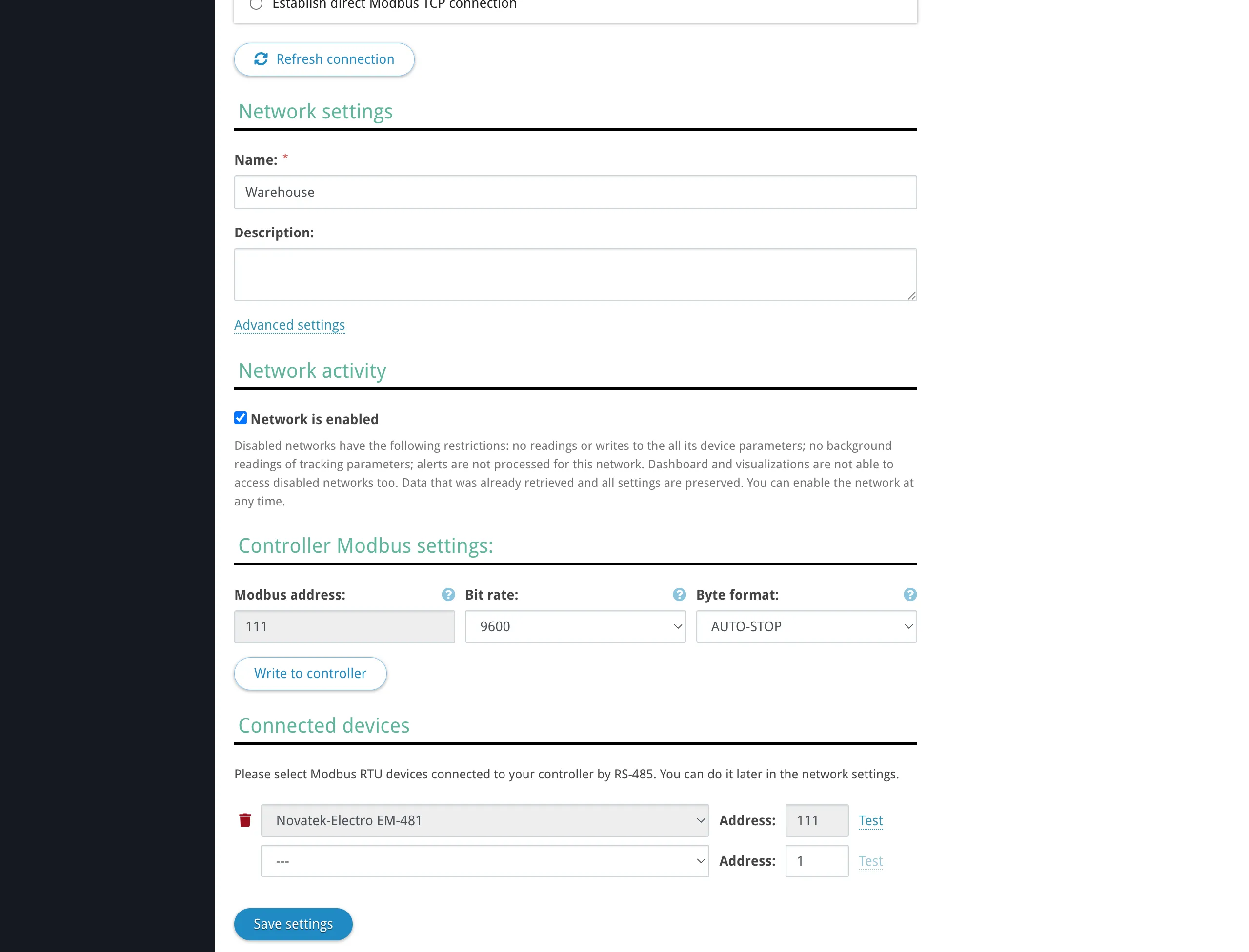
| Setting | Description |
|---|---|
| Name | A descriptive label for the network (e.g. “Warehouse”, “Office HVAC”). |
| Description | Optional free-text description. |
| Connection | How Overvis reaches the controller: reverse connection (PIN code or activation code) or direct Modbus TCP (IP address and port). See Connecting Equipment for details on each method. |
| Modbus TCP controller | The model of the communication controller (e.g. MC252, EM-482, EM-130, or “Other Modbus TCP device” for third-party equipment). Determines which built-in features and settings are available. Matches the Modbus TCP controller: field in the network form. |
| Gateway Modbus address | The Modbus unit ID of the controller itself on the TCP link (default: 111). This is used when Overvis needs to address the gateway directly — for example, to read or change serial port settings on an Overvis-compatible controller. This is not the address of any field device. |
| Controller access passwords | Passwords sent to the controller after connecting. Some controllers require one or more passwords for read and/or write access. Multiple passwords can be configured (e.g. separate read and write passwords). |
| Maximum inflight requests | How many Modbus requests Overvis sends to this network simultaneously (default: 8). Increasing this value allows parallel requests, which can speed up polling when the controller supports it. Many controllers process RS-485 requests sequentially regardless, so a high value may not improve performance and can cause timeouts. |
| Enabled / disabled | Whether communication is active. See Disabling. |
| RS-485 (bit rate, byte format) | On supported controllers, a Controller Modbus settings block appears (bit rate and byte format). Overvis reads the current values from the controller and can write changes over the same link. Only shown when the controller type supports it and the network is connected. See Serial communication settings for choosing values that match your field devices. |
Network settings do not include the Modbus addresses of devices behind the controller, parameter register addresses, or data interpretation rules. Those belong to the device and parameter levels.
Network Page
Section titled “Network Page”The network page shows the gateway connection status and the list of all devices in the network.
The device list shows each device’s Modbus ID, name, number of tracked parameters, update period, and the time of the last reading. From this page you can enable or disable individual devices, open device settings, or delete a device.
For networks using a reverse connection (PIN code or activation code), the page also shows connection status and management actions such as dropping the connection.
Devices
Section titled “Devices”A device represents one Modbus unit inside a network — one addressable endpoint behind the controller. All devices in a network share the same controller connection.
The key identifier is the Modbus ID (unit ID, 0–255), which must be unique within the network and match the address configured on the physical device (DIP switches, front panel, or device configuration software).
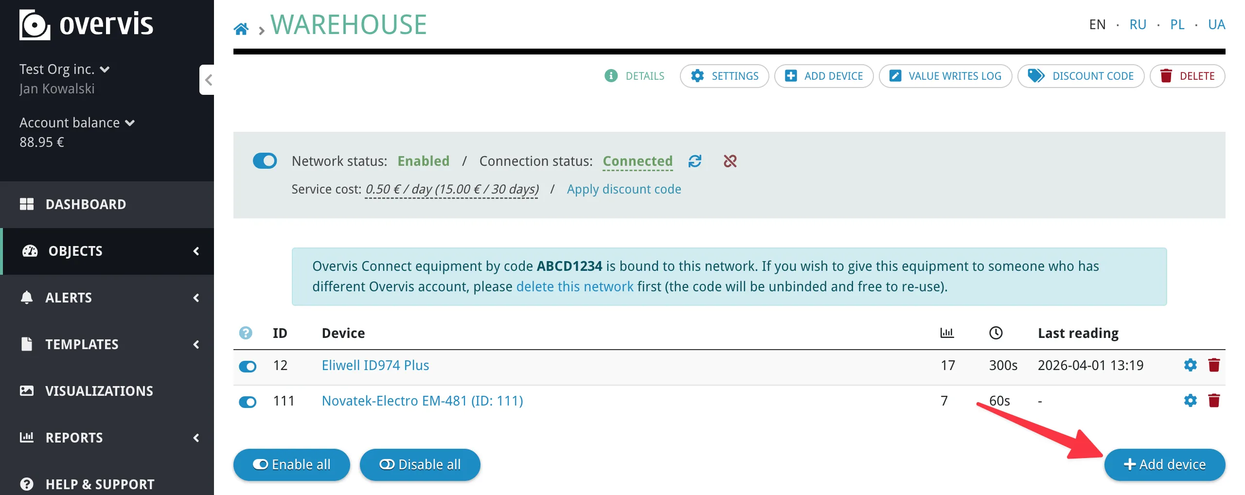
Creating a Device
Section titled “Creating a Device”To create a device, open the network page and click Add device.
The create form asks for:
- Name and optional description.
- Modbus ID — the unit address of the physical device.
- Device template (optional) — select a template to pre-configure all parameters automatically. You can choose from built-in templates or templates created within your organization. See Device Templates for details.
If no template is available for your device, you can add parameters manually after creating the device.
After creating the device, Overvis begins communicating with it immediately (if the network is connected and the device is enabled).
Device Settings
Section titled “Device Settings”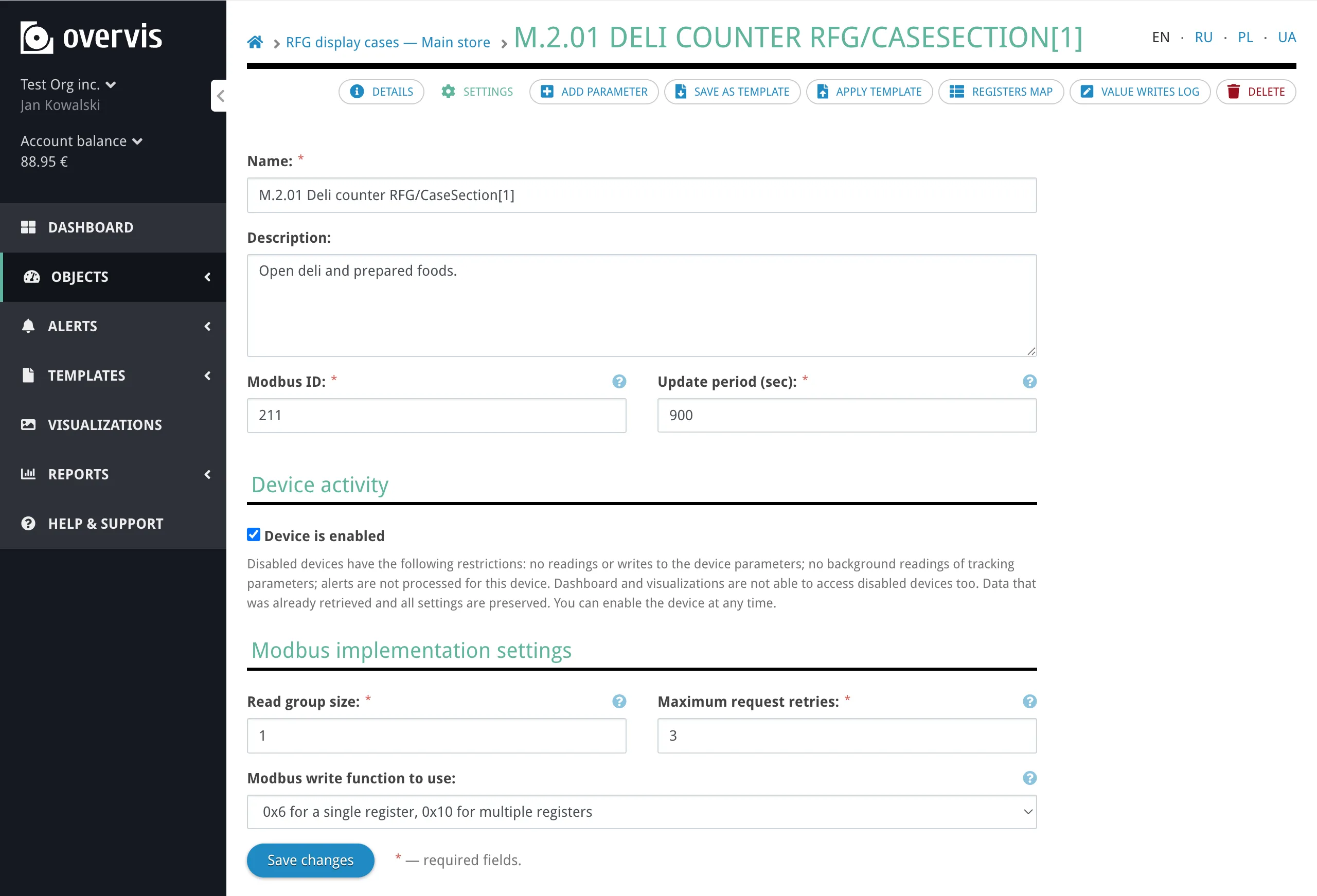
| Setting | Default | Description |
|---|---|---|
| Modbus ID | (set when creating the device) | The Modbus unit ID (0–255). Must match the physical device address and be unique within the network. |
| Update period | 10 minutes | How often Overvis performs background reads for tracked parameters on this device. Shorter periods give more frequent data but increase network traffic. |
| Read group size | 1 | The maximum number of consecutive registers Overvis combines into a single Modbus read request. The device settings UI accepts 1–16; the database allows up to 255 (for example when set via template import). Higher values reduce the number of requests by reading larger register blocks at once, which speeds up polling. A value of 1 means each parameter is read individually. |
| Modbus write function | 0x6 for a single register, 0x10 for multiple registers (default) | Which Modbus function code to use when writing parameter values. The default option matches this label in the UI (Overvis chooses function 06 for single-register values and 16 for multi-register values). Other options: Always use function 06 (force single-register writes), Always use function 16 (force multi-register writes). Some devices only accept one specific write function — consult the device documentation. |
| Maximum retries | 3 | How many times Overvis retries a request after a timeout or no-response error before marking the device as unreachable. |
| Enabled / disabled | Enabled | Whether communication is active. See Disabling. |
Device settings do not define the connection path to the controller (that is the network level) or how individual register values are decoded (that is the parameter level).
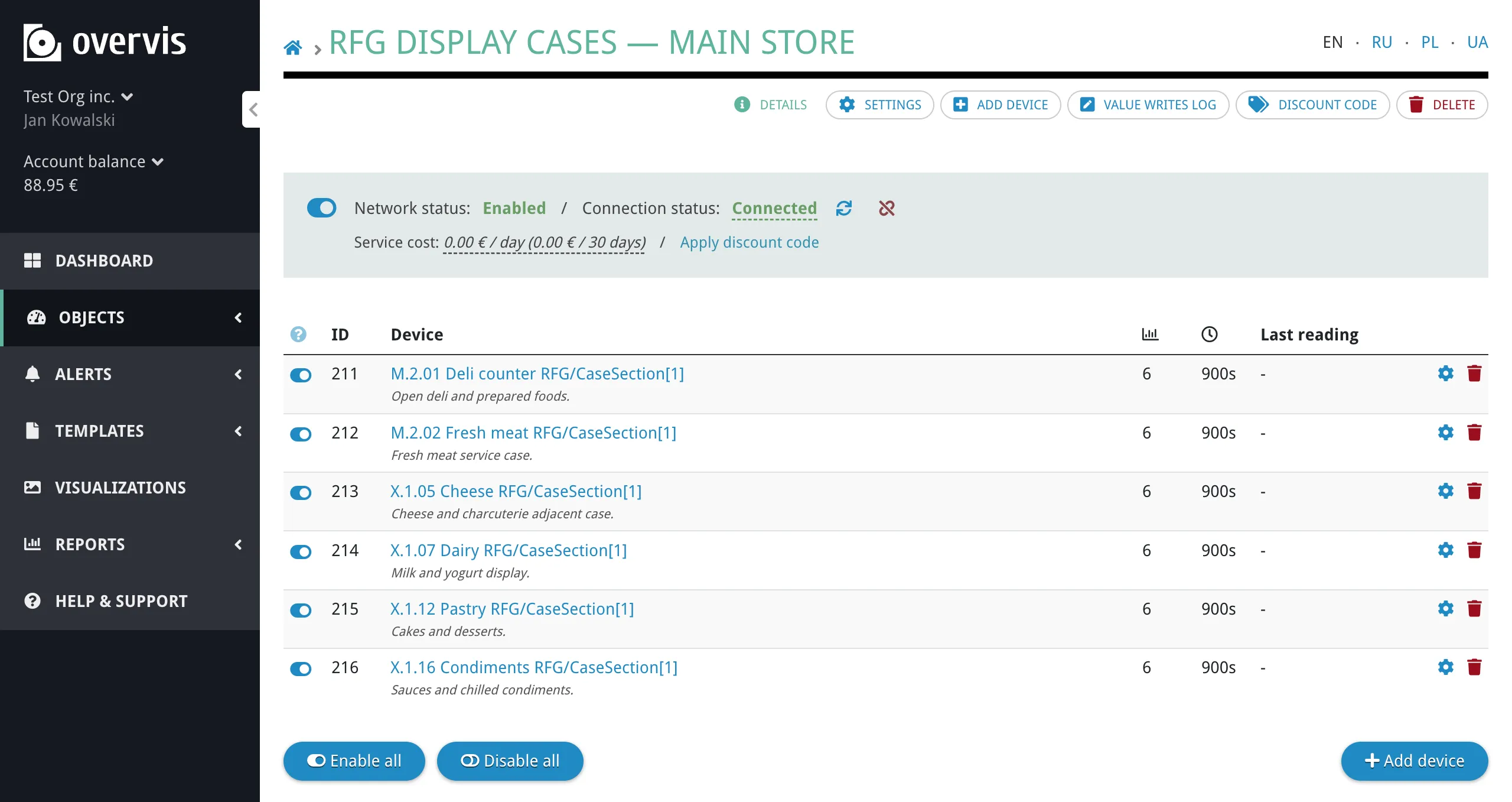
Device Page
Section titled “Device Page”The device page is where you view and interact with parameter values. Parameters are organized by their behavior flags (tracked, programmable) into sections — see Behavior Flags for definitions.
The device page shows:
- Last reading — the timestamp of the most recent background reading for this device.
- Next reading — when the next scheduled background read will occur.
- Parameter list — all parameters organized into three sections (tracked, programmed, untracked), with categories within each section.
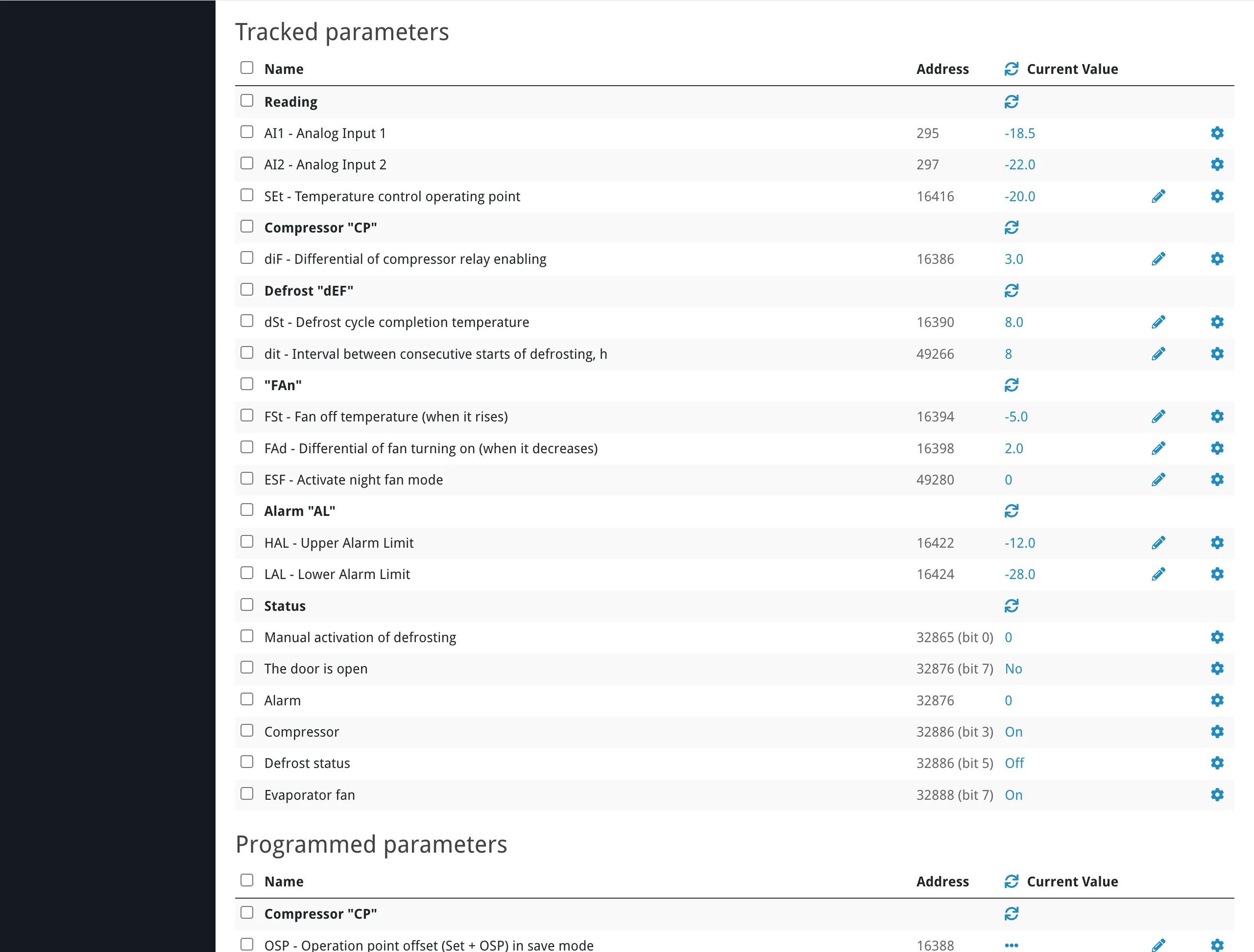
Reading Values
Section titled “Reading Values”Tracked parameters display their last stored value by default. This value may be from the most recent background poll, not necessarily live.
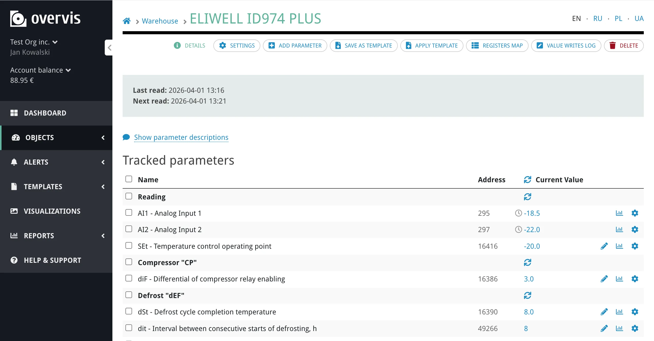
To read a live value from the device:
- Click on a parameter’s value to start reading it from the device in real time. Overvis will keep refreshing that value automatically until you click it again. This works for both tracked and untracked parameters.
- Click the refresh icon in the column header to read all visible parameter values at once.
Untracked parameters show ”---” until you trigger an on-demand read.
Writing Values
Section titled “Writing Values”Programmable parameters have a pencil icon next to their value. Clicking it opens an inline editor:
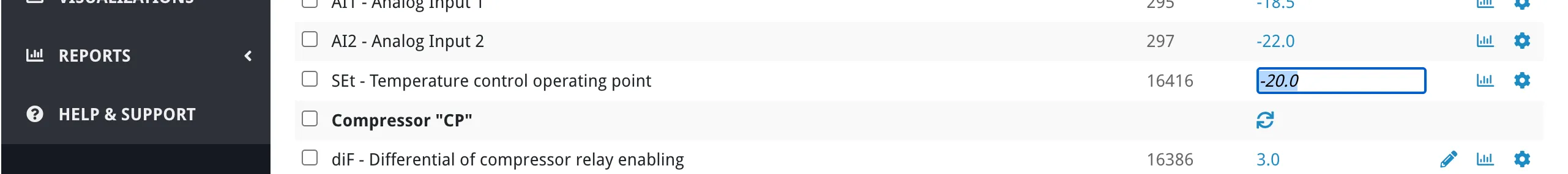
- For numeric parameters, a text input appears where you enter the new value.
- For enumeration parameters, a dropdown appears with the defined labels (e.g. “Standby”, “Heating”, “Cooling”) — Overvis writes the corresponding numeric value to the device.
The write is sent to the device immediately. If the write fails, Overvis shows an error message with the reason.
Parameters
Section titled “Parameters”A parameter is the smallest operational object in the hierarchy. It represents one value definition on a device — a single piece of data that Overvis can read from or write to.
A parameter can represent:
- One holding register or input register.
- One coil or discrete input.
- One bit inside a register.
- A contiguous range of bits inside a register.
- A multi-register value (e.g. a 32-bit float spanning two registers, or a 64-bit integer spanning four).
- A string value spanning multiple registers.
Creating and Editing Parameters
Section titled “Creating and Editing Parameters”To add a parameter manually, open the device page and click Add parameter. The form includes all fields described below: name, address, register type, value type, behavior flags, conversion settings, and optional enumeration values.
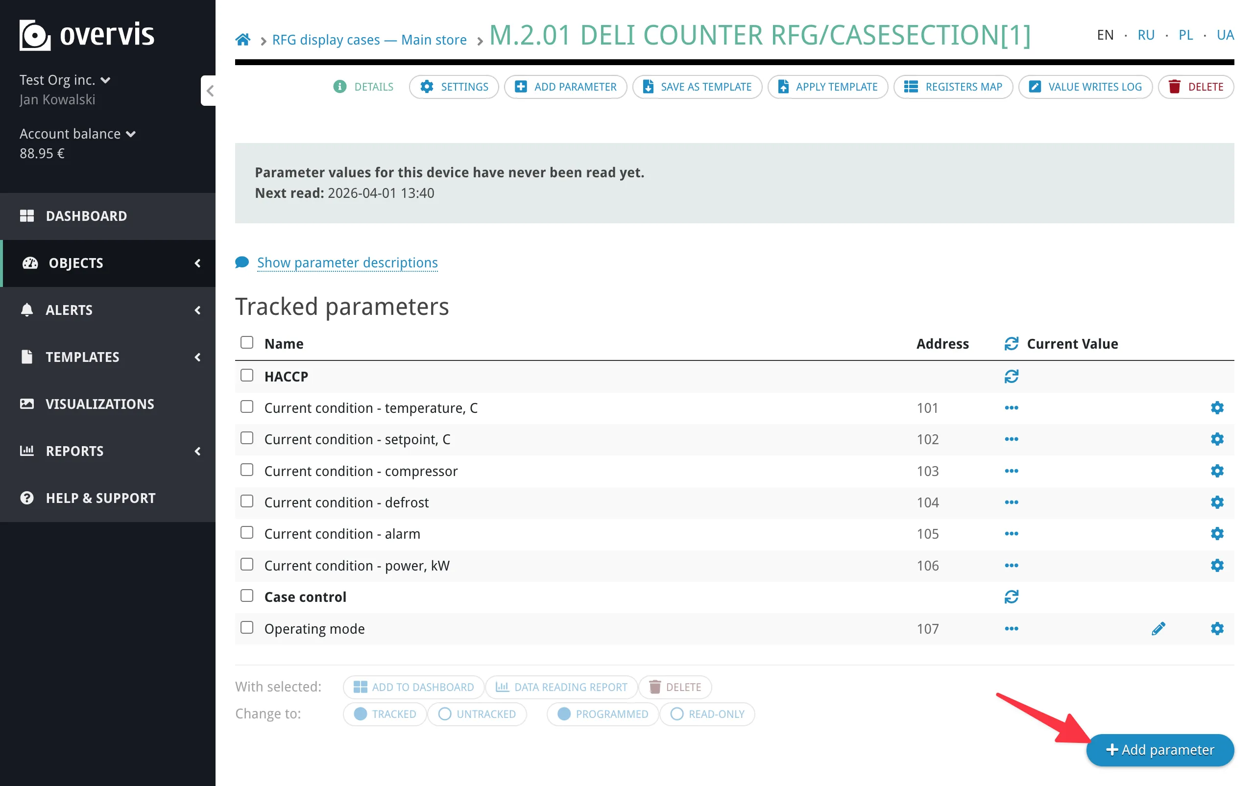
To edit an existing parameter, click its name on the device page to open the parameter settings. The same form appears with the current values pre-filled.
If your device has many parameters, using a device template is faster than adding them one by one.
Parameter Settings
Section titled “Parameter Settings”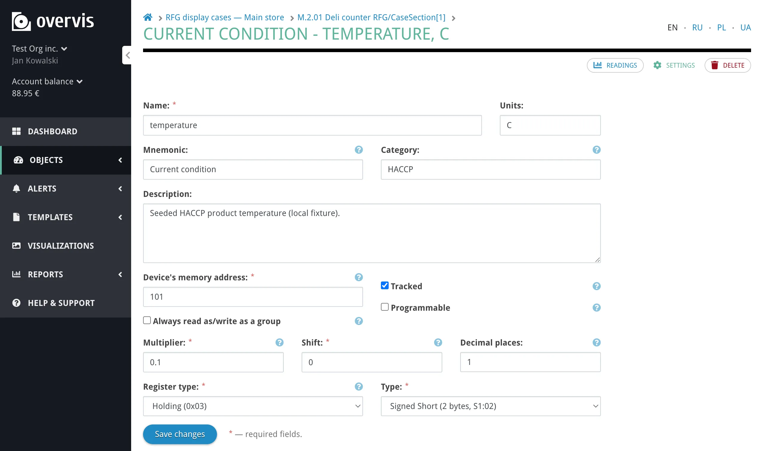
Metadata
Section titled “Metadata”Each parameter stores the following identification and organizational fields:
| Field | Description |
|---|---|
| Name | The primary display label (e.g. “Current Temperature”, “Setpoint”, “Operating Mode”). |
| Mnemonic | An optional short code or abbreviation (up to 20 characters), typically from the device documentation (e.g. “PV”, “SV”, “St”). When set, Overvis displays it before the name. |
| Description | Optional explanatory text. |
| Category | Groups parameters within the device page (e.g. “Measurement”, “Settings”, “Diagnostics”). Categories are purely organizational — they do not affect addressing, polling, or writes. Parameters without a category appear under “Uncategorized”. |
| Units | Measurement unit label for display (e.g. °C, kWh, V, A, %). |
Address
Section titled “Address”Each parameter maps to a location in the device’s Modbus memory map. The full address is defined by the combination of:
| Field | Description |
|---|---|
| Device’s memory address | The Modbus register number (0–65535). Labeled Device’s memory address: in the parameter form (same concept as “register address” in manuals). |
| Register type | The Modbus register class — see Register Types. |
| Bit position | For bit and bit-group value types: which bit within the register (0 = least significant). |
| Bit group length | For bit-group value types: how many consecutive bits the value spans. Labeled Bit group length: in the parameter form. |
| String length | For string value types: how many registers the string occupies. |
The same device memory address can legitimately appear in more than one parameter when the parameters represent different views of the same data — for example, a whole-register numeric value and a single bit flag inside that same register, or several independent bit flags from one status register.
Register Types
Section titled “Register Types”Overvis supports all four Modbus register types:
| Register type | Modbus function codes | Access | Size |
|---|---|---|---|
| Holding register | FC 03 (read), FC 06/16 (write) | Read/write | 16-bit word |
| Input register | FC 04 (read) | Read-only | 16-bit word |
| Coil | FC 01 (read), FC 05/15 (write) | Read/write | Single bit |
| Discrete input | FC 02 (read) | Read-only | Single bit |
Holding registers are the most common type in practice. Coils and discrete inputs are inherently single-bit and always use the Bit value type.
Value Types
Section titled “Value Types”The value type defines how the raw register data is interpreted. It determines the binary layout, byte order, and number of registers a parameter occupies.
Overvis supports a wide range of value types:
| Category | Value types | Registers |
|---|---|---|
| 8-bit integers | Unsigned Byte, Signed Byte | 1 |
| 16-bit integers | Unsigned/Signed Short (big-endian and byte-swapped variants) | 1 |
| 32-bit integers | Unsigned/Signed Int (big-endian, byte-swapped, and word-swapped variants) | 2 |
| 64-bit integers | Unsigned/Signed Long (big-endian, byte-swapped, and word-swapped variants) | 4 |
| Floating point | IEEE 754 Float (big-endian, byte-swapped, word-swapped) | 2 |
| Double precision | IEEE 754 Double (big-endian, byte-swapped, word-swapped) | 4 |
| BCD | Unsigned 16-bit BCD | 1 |
| Bit | Single bit within a register | 1 |
| Bit group | Contiguous range of bits within a register | 1 |
| Enumeration | Numeric value with named states — see Enumeration Parameters | 1 |
| String | Byte String (2 ASCII characters per register) or Word String (1 ASCII character per register) | Variable |
| IP address | IPv4 address in byte order or word order | 2 |
| MAC address | MAC address in byte order or word order | 3 |
| Special | Unsigned 48-bit Int (3 registers), Unsigned 3 Last Bytes in Words (3 registers) | 3 |
Byte order matters. Many devices store multi-byte values in big-endian order (most significant byte first), but some use byte-swapped or word-swapped layouts. If a value reads as garbage or an unreasonable number, the byte order is likely wrong — try the other variants for the same data width.
Behavior Flags
Section titled “Behavior Flags”Three flags control how Overvis treats a parameter operationally:
Tracked — a tracked parameter participates in background polling and persistent storage:
- Overvis reads it periodically according to the parent device’s update period.
- Each reading is saved to the database with a timestamp.
- Historical data is available in charts, reports, and the dashboard.
An untracked parameter is still part of the device model and can be read on demand, but it is not polled automatically and its values are not stored.
Programmable — a programmable parameter can be written through Overvis. Non-programmable parameters are read-only in the Overvis UI regardless of whether the underlying register supports writes.
Tracked and programmable are independent flags. A parameter can be:
- Tracked only — monitored and stored, but not writable through Overvis.
- Programmable only — writable, but not automatically polled or stored.
- Both — polled, stored, and writable.
- Neither — exists as part of the device model for on-demand reads only.
Always read/write as a group — when enabled, Overvis keeps the entire multi-register value together in one Modbus request instead of allowing it to be split across separate requests. This is relevant for parameters that span more than one register (e.g. 32-bit floats, 64-bit integers, strings) where partial reads could produce corrupted values if the device does not update all registers at the same instant.
Parameter Groups on the Device Page
Section titled “Parameter Groups on the Device Page”On the device page, parameters are grouped into three sections based on these flags:
- Tracked parameters — tracked flag on (regardless of whether also programmable).
- Programmed parameters — programmable but not tracked. The label Programmed means programmable, not custom PLC-style programming.
- Untracked parameters — neither tracked nor programmable.
Within each section, parameters are further grouped by category.
Value Conversion
Section titled “Value Conversion”After reading a raw value from the device, Overvis can transform it for display using three parameter-level settings:
| Setting | Description |
|---|---|
| Multiplier | Scales the raw value. Applied as multiplication. |
| Shift | Adds a fixed offset after scaling. |
| Decimal places | Controls how many decimal digits are shown in the formatted value. |
The conversion formula is:
displayed value = raw value × multiplier + shift
For example, if a temperature sensor stores values in tenths of a degree (raw value 235 means 23.5 °C), set multiplier to 0.1 to convert to degrees. If the device stores a value with a fixed offset, use shift to compensate.
Overvis stores raw register values in the database and applies conversion at display time. This means multiplier and shift affect how all readings appear — both historical and new. Changing the multiplier retroactively changes how old data looks in charts and reports. Decimal places affects formatting only, not the stored value.
When neither multiplier nor shift is set, Overvis treats the value as unscaled: the displayed value equals the raw register value (equivalent to multiplier 1 and shift 0).
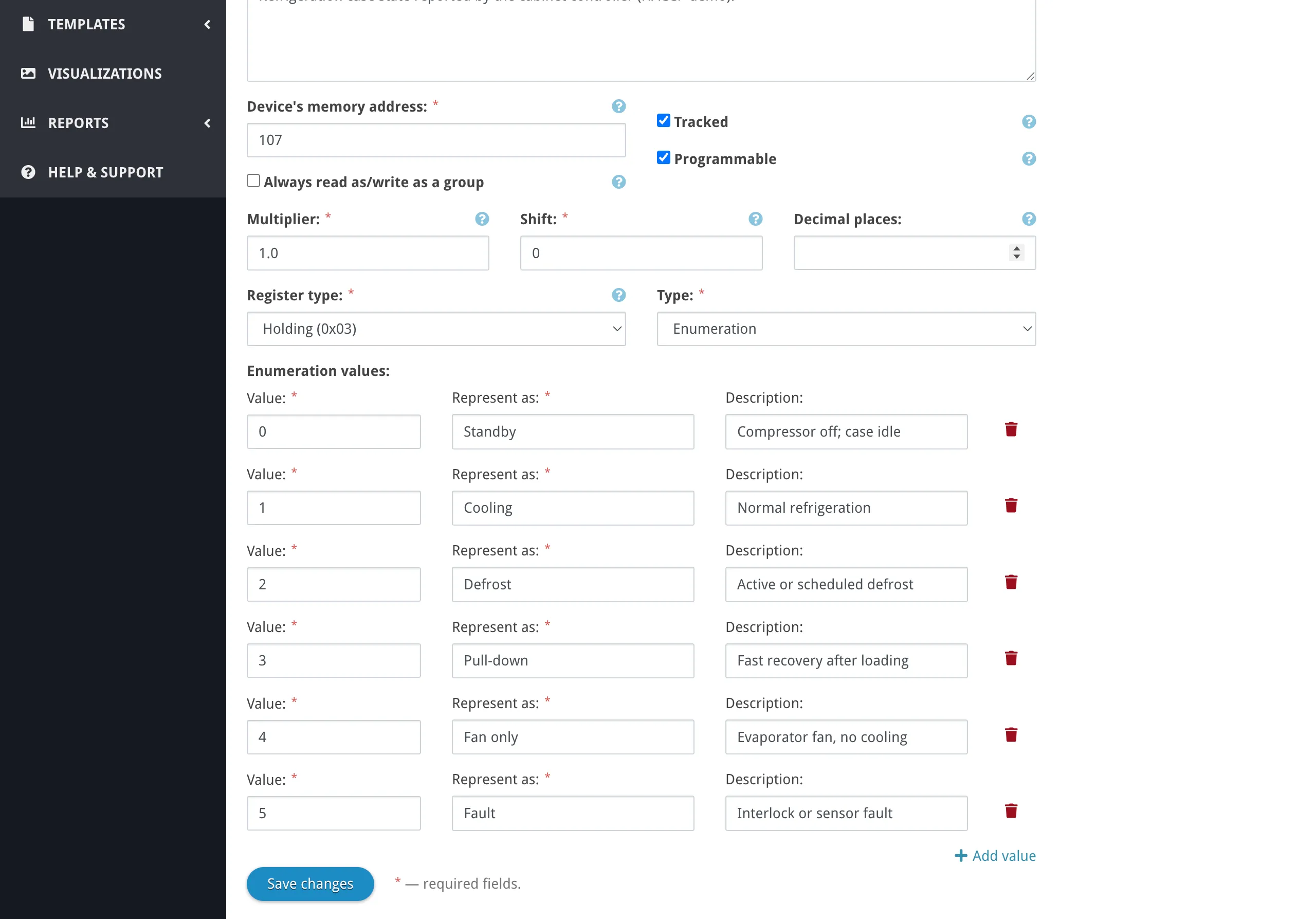
Enumeration Parameters
Section titled “Enumeration Parameters”Enumeration is a value type for parameters where a numeric register encodes a discrete state or mode — for example, machine status, operating mode, or alarm type. At the Modbus level it works like any other numeric parameter, but Overvis maps the raw values to human-readable labels using a lookup table.
Each entry in the enumeration table contains:
| Field | Description |
|---|---|
| Value | The raw numeric value from the device. |
| Represent As | The display label shown in the UI (e.g. “Running”, “Standby”, “Error”). |
| Description | Optional explanatory text for this state. |
For example, a parameter “Operating Mode” might have the mapping:
| Value | Represent As |
|---|---|
| 0 | Standby |
| 1 | Heating |
| 2 | Cooling |
| 3 | Error |
When reading, Overvis shows “Heating” instead of 1. When writing a programmable enumeration parameter, the user selects from a dropdown of the defined labels, and Overvis writes the corresponding numeric value.
Enumeration tables can be shared across multiple parameters, which is useful when several parameters on different devices use the same set of states.
Min/Max Value Limits
Section titled “Min/Max Value Limits”Parameters can optionally define minimum and maximum values. These are informational boundaries — they help constrain write inputs in the UI and provide context for expected value ranges. They do not affect how values are read from the device.
Troubleshooting
Section titled “Troubleshooting”Parameter value looks wrong (garbage, implausibly large, or zero)
Section titled “Parameter value looks wrong (garbage, implausibly large, or zero)”This usually means the value type or byte order does not match what the device actually sends. For example, reading a 32-bit float as a 16-bit unsigned integer, or using big-endian byte order when the device uses word-swapped order.
How to fix:
- Open the parameter’s settings and check the value type. Confirm it matches the device documentation for that register.
- If the data width is correct but the value still looks wrong, try the other byte-order variants for the same width (e.g. switch from “Float big-endian” to “Float word-swapped” or “Float byte-swapped”).
- Check the device memory address — some device manuals use 1-based register numbering while Overvis uses 0-based. If the manual says register 40001, the Overvis address is typically 0 (holding register).
- If a multiplier or shift is configured, verify the conversion formula produces reasonable results.
Device shows as unreachable
Section titled “Device shows as unreachable”The device is not responding to Modbus requests within the timeout.
Common causes and fixes:
- Wrong Modbus ID — verify that the Modbus ID set in Overvis matches the address configured on the physical device. Check DIP switches, front panel settings, or the device configuration software.
- Device not powered or not connected — confirm the device is powered on and wired to the RS-485 bus connected to the gateway controller.
- Network is disconnected — check the network’s connection status indicator. If the gateway itself is offline, no devices in that network can be reached. See Connecting Equipment — Troubleshooting.
- RS-485 settings mismatch — the baud rate and byte format (parity, stop bits) on the gateway must match the device. Mismatched serial settings cause communication failures. See Connecting Equipment — Serial Settings.
- Duplicate Modbus IDs — two physical devices on the same RS-485 bus with the same Modbus address will interfere with each other and cause intermittent failures or corrupted responses.
On-demand read shows ”---”
Section titled “On-demand read shows ”---””A ”---” value means Overvis has no stored reading for that parameter. This is normal for untracked parameters that have never been read manually.
How to fix:
- Click on the value field to trigger an on-demand read from the device. If the device is online and the parameter address is valid, the current value will appear.
- If you need historical data for this parameter, enable the tracked flag in parameter settings.
- If the on-demand read fails, the device may be unreachable — check the device unreachable section.
Write to a parameter fails
Section titled “Write to a parameter fails”When Overvis cannot write a value to a parameter, common causes include:
- Parameter is not programmable — writing is only allowed for parameters with the programmable flag enabled. Enable it in parameter settings.
- Wrong write function — some devices only accept function code 06 (single-register write) or function code 16 (multi-register write), but not both. Change the Modbus write function in device settings from “Normal” to the specific function your device expects.
- Register is read-only — the underlying Modbus register type (e.g. input register, discrete input) does not support writes. Check the device documentation.
- Value out of device range — the device may reject values outside its internal limits even if the Overvis parameter allows them.
- Controller access password missing — some controllers require a write-access password. Check the controller access passwords in network settings.
Polling is slower than expected
Section titled “Polling is slower than expected”If tracked parameters update less frequently than the configured update period:
- Multiple devices sharing one controller — all devices in a network share the same connection. If many devices with many parameters exist on one network, polling all of them takes time. The actual cycle time may exceed the update period.
- Read group size too low — a read group size of 1 means each parameter is read individually, which requires one Modbus request per parameter. Increasing the read group size (within the 1–16 range in the device settings UI, or up to 255 when allowed) combines consecutive registers into fewer requests, which speeds up polling.
- High inflight requests with slow controller — many RS-485 controllers process requests sequentially. Setting inflight requests too high may cause queued requests to time out while waiting, triggering retries and further slowing the cycle.
- Frequent retries — if some devices on the bus are unreachable or intermittently failing, Overvis spends time on retries before moving on. Each retry waits for a timeout before it counts as failed.
Common Questions
Section titled “Common Questions”How do I change which parameters are tracked?
Section titled “How do I change which parameters are tracked?”On the device page, you can bulk-change behavior flags. Select parameters using the checkboxes and use the buttons below the parameter list to mark them as tracked or untracked. You can also change tracking in individual parameter settings.
Enabling tracking starts background polling and data storage for that parameter. Disabling tracking stops polling and storage, but existing historical data is preserved.
Can I use the same register address for multiple parameters?
Section titled “Can I use the same register address for multiple parameters?”Yes. This is common when one register contains multiple independent bit flags — you can create separate bit-type parameters for each flag, all pointing to the same register address but with different bit positions. Similarly, you might have one parameter reading the full register as a numeric value and another parameter reading a single status bit from it.
What happens to historical data if I change parameter settings?
Section titled “What happens to historical data if I change parameter settings?”Changing value type, multiplier, or shift retroactively changes how all stored readings appear — see Value Conversion. Changing the register address or register type makes the parameter read from a different location going forward; old data still shows the values from the previous address.
Related Features
Section titled “Related Features”Networks, devices, and parameters are the foundation for other Overvis features:
- Dashboard — tracked parameters can be pinned to the organization dashboard for at-a-glance monitoring. The dashboard groups displays by network and device.
- Alerts — threshold and offline alerts are configured on individual parameters or devices. Alert state is shown on the device page and dashboard.
- Visualizations — custom interactive dashboards that read parameter values in real time.
- Parameter Values Report — historical data exports for tracked parameters.
- HACCP Reports — food safety compliance reports built from tracked temperature parameters.
- Device Templates — reusable parameter configurations for quick device setup.