OPCB-221B Operating Manual
This Operating Manual explains the design, safety requirements, operating rules, and maintenance procedures for the Overvis OPCB-221B controller.
The Quality Management System of the device designing and production complies with the requirements of ISO 9001:2015.
Purpose
Section titled “Purpose”The Controller OPCB-221B (hereinafter referred to as the “Controller”, “Product”, “Device”, or “OPCB-221B”) provides MODBUS communication between clients and servers in TCP networks (Internet) and between devices in the RS-485 interface.
OPCB-221B is used to remotely monitor and control the operation of:
- Refrigeration controllers
- HVAC systems controllers
- Agricultural smart devices
- Power network relays, meters, and other electrical equipment
- Industrial IoT devices
- Industrial sensors and meters
- Other MODBUS-compatible electronics
OPCB-221B Features
Section titled “OPCB-221B Features”- MODBUS RTU/TCP converter
- Built-in Overvis cloud support (www.overvis.com)
- Serves as TCP server or client, MODBUS RTU master or slave
- RS-485 network extension
- MODBUS ASCII mode support
- Supports LAN and/or Wi-Fi connection
- Optional 3G/LTE connection using an external USB modem
- Wi-Fi Access Point mode
- Web interface, accessible from the local network, via Wi-Fi Access Point, or using Overvis cloud connection
- Remote configuration (using MODBUS or web interface)
- RS-485 network settings: baud rate, parity, response timeout
- Supports multiple RS-485 networks
- MODBUS request debugging tools
- Automatic or manual firmware updates
- HTTP API
Terms and Abbreviations
Section titled “Terms and Abbreviations”| Term | Definition |
|---|---|
| Wi-Fi station | A device connected to another device through Wi-Fi (access point) |
| Wi-Fi access point | A device enabling connection to it through Wi-Fi |
| DHCP | A protocol enabling network units to automatically obtain TCP/IP parameters (IP address) |
| HTTP | The transmission protocol for web pages and other data using client-server technology |
| IP (address) | The address of the unit, which is unique within one network that is operated according to IP protocol |
| IPv4 | A four-byte IP address |
| MAC (address) | The address used in network transmissions for device identification. It is typically globally unique |
| MAC-48 | A six-byte MAC address |
| MODBUS | The standard packet communication protocol based on the client-server technology intended for industrial electronic devices |
| MODBUS RTU | The devices linking protocol, where the packet is transmitted byte by byte |
| MODBUS ASCII | The devices linking protocol, where the packet is transmitted in ASCII characters |
| MODBUS TCP | MODBUS packet transmission protocol according to TCP/IP standard |
| WEB | The server documents access system used on the Internet |
| Wi-Fi | A family of standards for data transmission via radio channels |
Complete Set
Section titled “Complete Set”
Table 1 – Product Set
| Name | Quantity |
|---|---|
| 1. Controller OPCB-221B (with installed MicroSD memory card and integrated Wi-Fi antenna, 3 dBm) | 1 |
| 2. USB/RS-485 extension module (supporting up to 32 connected RS-485 devices) | 1 |
| 3. Power supply with USB Type-A output and DC Plug cable | 1 |
| 4. Ethernet cable | 1 |
| 5. Operation manual with Cloud Registration sticker | 1 |
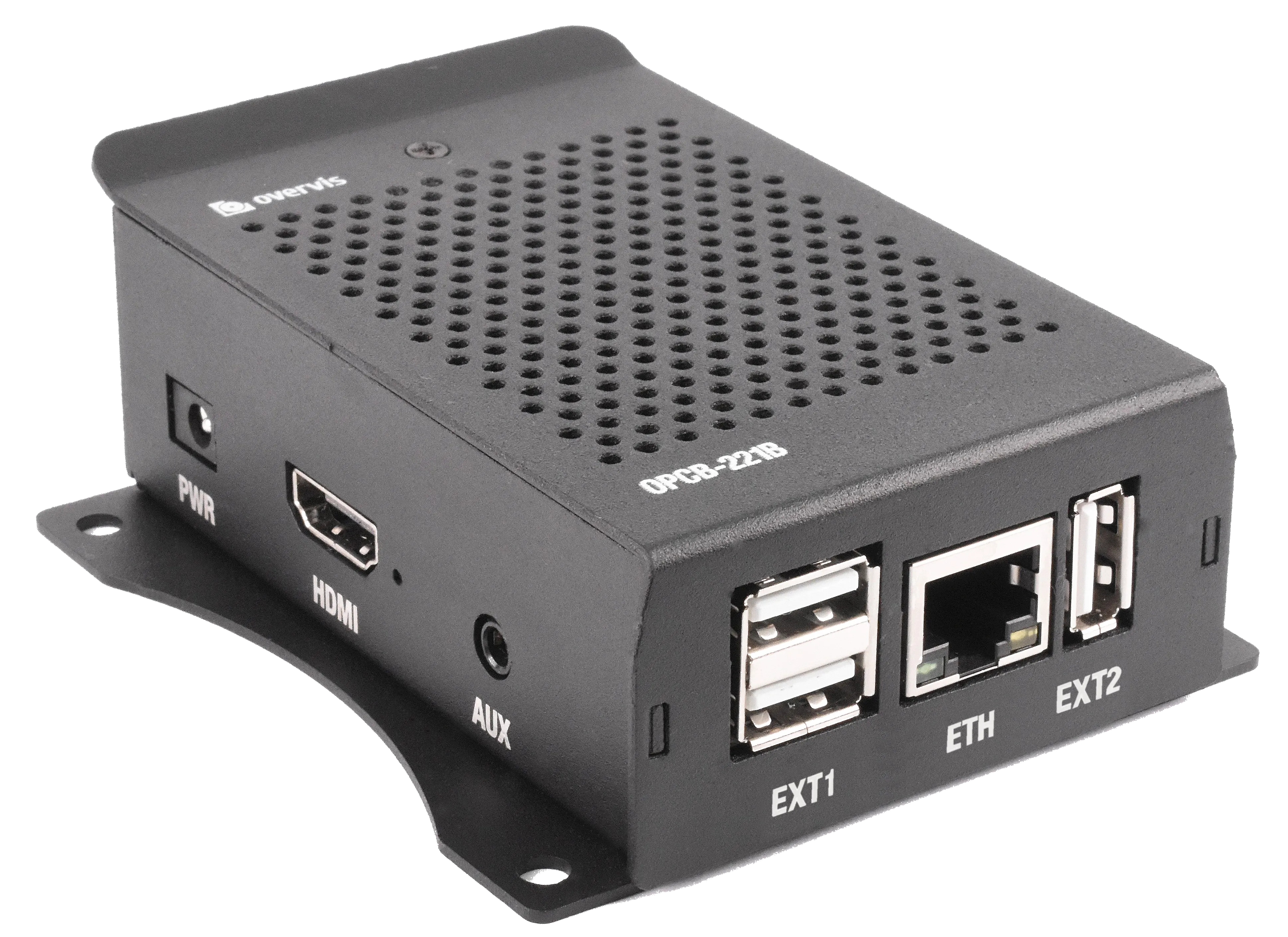
Overall Mounting Dimensions and Controls
Section titled “Overall Mounting Dimensions and Controls”


Figure 1 – OPCB-221B Overall and Mounting Dimensions
Connectors and Controls
Section titled “Connectors and Controls”- “EXT1” connectors: 2 USB Type-A connectors for connecting additional modules (e.g., RS-485 / RS-232 serial interface converters)
- “ETH” connector: 8P8C/RJ45 for wired connection to the local Ethernet network
- “EXT2” connector: USB Type-A connector for connecting additional modules (e.g., RS-485 / RS-232 serial interface converters)
- “PWR” connector: DC Plug for connecting a 5V DC power source with a power of at least 9W
- “HDMI” connector: HDMI output (not used)
- “AUX” connector: Audio output (not used)
- “MEM” slot: MicroSD card slot for accessing the pre-installed memory card
Technical Specifications
Section titled “Technical Specifications”OPCB-221B Controller
Section titled “OPCB-221B Controller”Table 2 – OPCB-221B Controller Main Technical Specifications
| Parameter | Value |
|---|---|
| Power supply voltage DC, V | 5.0 |
| Motherboard | Orange Pi PC Plus 1G RAM |
| TCP networks link interface | Ethernet, Wi-Fi |
| Ethernet communication interface | 10BASE-T/100BASE-T (twisted pair) |
| Wi-Fi frequency, GHz | 2.4 |
| Supported Wi-Fi standards | IEEE 802.11 b/g/n |
| Supported TCP/IP protocols | MODBUS TCP, HTTP, DNS, DHCP, WireGuard |
| Maximum number of incoming connections via MODBUS TCP protocol | 4 |
| Maximum number of outgoing connections via MODBUS TCP protocol | 4 |
| Maximum number of serial interfaces | 3 (through individual USB ports) |
| Supported serial interface protocols | MODBUS RTU, MODBUS ASCII |
| Supported serial MODBUS modes | Master, Slave |
| Maximum number of connected MODBUS devices | 255 |
| Built-in servers | MODBUS TCP, HTTP |
| Ready time at power up, s, no more than | 60 |
| Current consumption, mA, max | 2000 |
| Weight, kg, no more than | 0.200 |
| Overall dimensions HxBxL, mm, no more than | 99 × 82 × 36 |
| Product designation | Switchgear and control equipment |
| Rated operating condition | Continuous |
| Degree of protection | IP30 |
| Electric shock protection class | III |
| Climatic design version | NF 3.1 |
| Permissible contamination level | II |
| Galvanic insulation, kV: Power connector | – |
| Galvanic insulation, kV: Ethernet connector | 1.5 |
| Galvanic insulation, kV: USB | – |
| Installation (mounting) | Panel |
Standards Compliance:
- The product meets the requirements of the following standards: EN 60947-1; EN 60947-6-2; EN 55011; EN 61000-4-2
- The product retains its functionality in any position in space
- Case material: Aluminum
- Harmful substances in amounts exceeding maximum permissible concentrations are absent
USB-RS485 Extension Module
Section titled “USB-RS485 Extension Module”Table 3 – USB-RS485 Extension Module Technical Specifications
| Parameter | Value |
|---|---|
| Communication speed, bps | 300-921600 |
| Direction control | Hardware automatically determines and controls data transmission direction |
| Transmission distance (at low speed) | About 1200 meters |
| Transmission mode | Up to 32 nodes in point pairs (repeaters are recommended for more than 16 nodes) |
| Balance resistance | Onboard 120 Ohm, jumper-connectable |
| Current consumption, mA, max | 50 |
| Interface protection | Provides 600W lightning protection, surge and 15kV static protection |
| Galvanic insulation | Present |
| Weight, kg, no more than | 0.010 |
| Overall dimensions HxBxL, mm, no more than | 15×18×63 |
| Cross-section of wires to be connected, mm² | 0.13 – 0.82 |
| Tightening torque of terminal screws, N·m | 0.3 |
| Degree of protection | IP20 |
Power Adapter
Section titled “Power Adapter”Table 4 – Power Adapter Technical Specifications
| Parameter | Value |
|---|---|
| Input AC voltage range, V | 100-240 |
| Input AC current, mA | 500 |
| Input AC frequency range, Hz | 50/60 |
| Output voltage DC, V | 5.0 |
| Output current DC, mA, max | 3000 |
| AC inlet | EU 2 pin plug |
| DC connector | USB Type-A |
| Weight, kg, no more than | 0.065 |
| Overall dimensions HxBxL, mm, no more than | 80×30×75 |
| Degree of protection | IP20 |
| Electric shock protection class | II |
| Insulation voltage | Input/Output to outer case, 500VDC, greater than 10MΩ |
| Input to output withstand voltage | AC 3kV / 10mA, 3s |
Operating Conditions
Section titled “Operating Conditions”The product is intended for operation under the following conditions:
- Ambient temperature: -10 to +55 °C
- Atmospheric pressure: 84 to 106.7 kPa
- Relative humidity (at +25 °С): 30 to 80%
General Instructions
Section titled “General Instructions”When connecting to the RS-485 bus, use a twisted pair cable, cat. 1 or higher. Strip the ends of insulation by 4±0.5 mm and tighten with bushing tips. A shielded grounded cable is recommended.
DO NOT LEAVE ANY BARE WIRE PROTRUDING BEYOND THE TERMINAL BLOCK.
For reliable contact, tighten the terminal screws with the force indicated in the technical characteristics table.
When connecting to Ethernet, use the supplied cable, or a twisted pair cable of cat. 5e with an 8P8C (RJ45) plug.
When fixing the wires, avoid mechanical damage, twisting, or wearing down the insulation of wires.
Connection
Section titled “Connection”Before starting:
- Unpack and inspect the product for damage after transportation. If any damage is found, contact the supplier or the manufacturer.
- Before connecting to the power supply, keep the product under operating conditions for two hours (in case of possible condensation on the elements).
- Carefully study the operating manual.
- If you have any questions about the installation of the product, please contact technical support.

Figure 2 – Product Connection Diagram
Connect OPCB-221B according to Figure 2, in the following order:
-
Using a twisted-pair cable of category 1 or higher, connect the terminal block of the RS-485 module to the serial interface bus (or directly to a device with this interface).
-
If the product should have access to the Internet or LAN, use the Ethernet connection cable (included in the package) or a twisted pair cable of cat. 5e with an 8P8C (RJ45) plug to connect the “ETH” connector (8P8C/RJ45) to the local network or computer.
-
Ensure the memory card is present in the “MEM” slot (installed by the manufacturer).
-
Connect the RS-485 module to one of the “EXT1” or “EXT2” (USB Type-A) connectors.
-
Connect the power unit (included) to the “PWR” (DC Plug) connector.
-
Optionally: Secure the USB connections with plastic cable ties to avoid accidental disconnection.
-
Connect the power unit to the power supply network (220-240VAC, 50Hz).
OPCB-221B Operation
Section titled “OPCB-221B Operation”General Information
Section titled “General Information”OPCB-221B has a 32-bit processor running a POSIX-compliant OS (Armbian). It routes traffic between the USB extension modules, such as serial RS-485 / RS-232 interfaces (MODBUS RTU/ASCII protocols), and Ethernet/Wi-Fi LAN interfaces (MODBUS TCP protocol), possibly routed further to the Internet.
OPCB-221B has a built-in web interface that can be used for configuration.
OPCB-221B can connect to a cloud server for remote monitoring and configuration of the product and connected devices.
OPCB-221B provides a Wi-Fi Access Point (hotspot) to simplify the initial setup. Wi-Fi Access Point can be disabled in the settings.
OPCB-221B stores the operating system and data on the pre-installed microSD memory card. Removing or replacing the memory card will render the product inoperable.
Power Up and Reboot Sequence
Section titled “Power Up and Reboot Sequence”After powering up, OPCB-221B loads the operating system and sets up the communication interfaces. This process usually takes up to 1 minute.
With an internet connection provided, OPCB-221B automatically connects to the cloud server if allowed in the settings. By default, unconfigured OPCB-221B creates a Wi-Fi access point with SSID “OPCB_XXXXXX” (where XXXXXX are the last 6 characters of the device’s MAC) and a password specified on the Registration sticker (attached to this manual).
Soft Reboot: Use the web interface by pressing the “Reboot device” button on the “Control” page. This will finish all ongoing operations, store the data, and reboot the device within 1 minute.
Hard Reboot: Turn off the power by unplugging the device, wait 5 seconds, and then turn the power back on.
Operation via HTTP
Section titled “Operation via HTTP”OPCB-221B provides an HTTP web interface and HTTP REST API for web applications. OPCB-221B accepts HTTP connections via Ethernet or Wi-Fi interfaces on TCP port 80.
To access the HTTP web interface:
-
Connect to the OPCB-221B Wi-Fi access point with a PC or mobile device and open the following URL in the browser:
http://192.168.4.1/ -
Alternatively, using any PC or mobile device in the local network, open the IP address of the OPCB-221B in the browser. The OPCB-221B IP address can usually be found by accessing the local network router interface.
The default username for the web interface is “admin” with the password specified on the Registration sticker (attached to this manual).
OPCB-221B Operation via MODBUS (TCP/RTU/ASCII)
Section titled “OPCB-221B Operation via MODBUS (TCP/RTU/ASCII)”OPCB-221B receives MODBUS TCP requests via Ethernet or Wi-Fi interfaces and transmits them in MODBUS RTU or MODBUS ASCII format over the serial interface. Responses are converted to MODBUS TCP and sent back to the requesting side.
OPCB-221B can also be configured to receive MODBUS RTU or MODBUS ASCII requests via the serial interface and transmit them in MODBUS TCP format to specified IP addresses via Ethernet or Wi-Fi interfaces. In this case, the responses (converted to the request protocol) are sent back to the serial line.
Connections from a PC or mobile device can be made using any software MODBUS TCP clients.
MODBUS registers of the OPCB-221B are configurable in the web interface on the “Connections” page in the section “OPCB Modbus access.”
MODBUS routing between the connected devices is configured in the web interface on the “Connections” page in the section “Routing.”
OPCB-221B Operation Using the Overvis Cloud Server
Section titled “OPCB-221B Operation Using the Overvis Cloud Server”OPCB-221B can establish connections to the Overvis cloud server using any interface with Internet access. OPCB-221B communicates with the Overvis cloud using an Overvis VPN connection, which provides full encryption of traffic between the device and the Overvis cloud server.
Overvis VPN cloud connection is enabled by default and can be disabled in the settings.
The cloud operation can be configured and managed by creating an account on the Overvis cloud: https://www.overvis.com/
Registration Sticker Information
Section titled “Registration Sticker Information”The OPCB-221B product set includes an Overvis Cloud registration sticker. Sticker information includes:
- Model of the device (OPCB-221B)
- MAC address of the LAN interface
- Private key: The unique private key of the device for Overvis VPN access, also used as a unique registration code for the Overvis cloud. This key is needed to restore the device license in case of firmware reflashing
- PIN code: The unique PIN code for quick identification of the device on the Overvis cloud
- Wi-Fi SSID and password for the initial connection to the Wi-Fi Access Point
- Default username and password for web interface access
- Quick setup link (with QR-code) for easy connection to the Overvis cloud
Access the link on the sticker and follow the instructions on the Overvis website to set up the device cloud operation and access the OPCB-221B interface through the Overvis cloud.
Factory Reset
Section titled “Factory Reset”A partial factory reset can be performed in one of the following ways:
Using a control key USB flash drive:
Write an empty file or an empty folder named "RESET_CONF" to a USB flash drive, then connect it to one of the “EXT1” or “EXT2” slots to reset the settings to the factory defaults. The reset may take up to 30 seconds; the USB flash drive can be disconnected afterward.
Through the web interface: Use the “Control” page in the web interface.
Firmware Update
Section titled “Firmware Update”Device firmware is updated continuously by the manufacturer. By default, the new version is installed automatically after the device is powered on or within 24 hours of operation. Automatic updates guarantee the backward compatibility of all OPCB-221B functions. Releases without backward compatibility require manual installation.
The currently installed version is displayed in the OPCB-221B web interface. The changelog for each version is available here: https://github.com/overvis/opcb-release/blob/opcb/CHANGELOG.md
Manual Firmware Update and Full Factory Reset
Section titled “Manual Firmware Update and Full Factory Reset”A manual update requires a full factory reset by uploading a new firmware image to the SD memory card. All current firmware images can be found on the release page: https://github.com/overvis/opcb-release/releases
Initial Setup
Section titled “Initial Setup”The device can be configured via the web interface. Configuration parameters are stored in a file on the SD memory card.
Step 1: Access the Web Interface
Section titled “Step 1: Access the Web Interface”After the device is plugged in and operational, access the web interface by connecting to the Wi-Fi Access Point or using the local network.
By default, an unconfigured OPCB-221B creates a Wi-Fi access point with SSID “OPCB_XXXXXX” (where XXXXXX are the last 6 characters of the device’s MAC) and a password specified on the Registration sticker (attached to this manual).
Connect to the OPCB-221B Wi-Fi access point with a PC or mobile device and open the following URL in the browser: http://192.168.4.1/
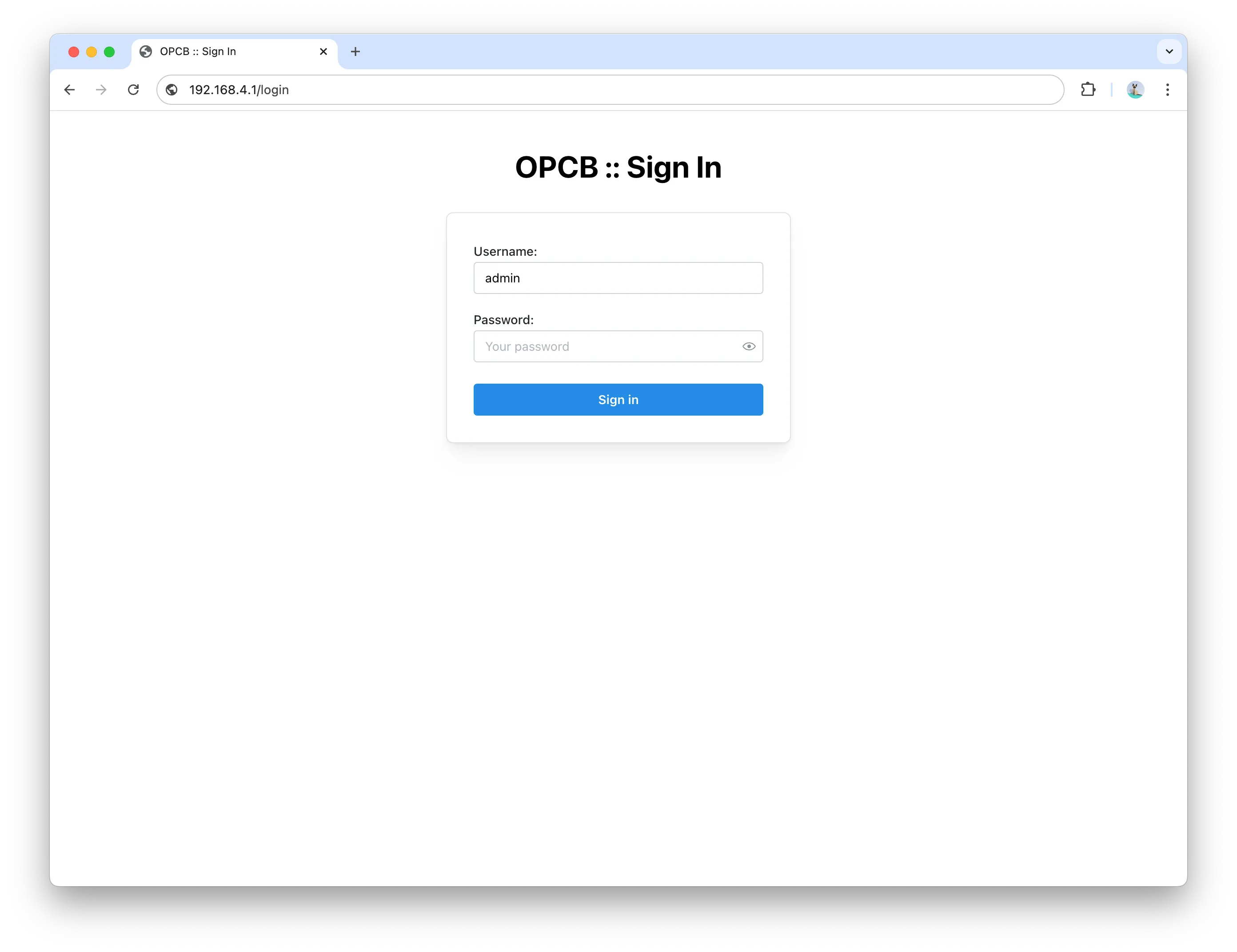
Step 2: Log In
Section titled “Step 2: Log In”Log in to the web interface using the default username “admin” and the password specified on the Registration sticker (attached to this manual).
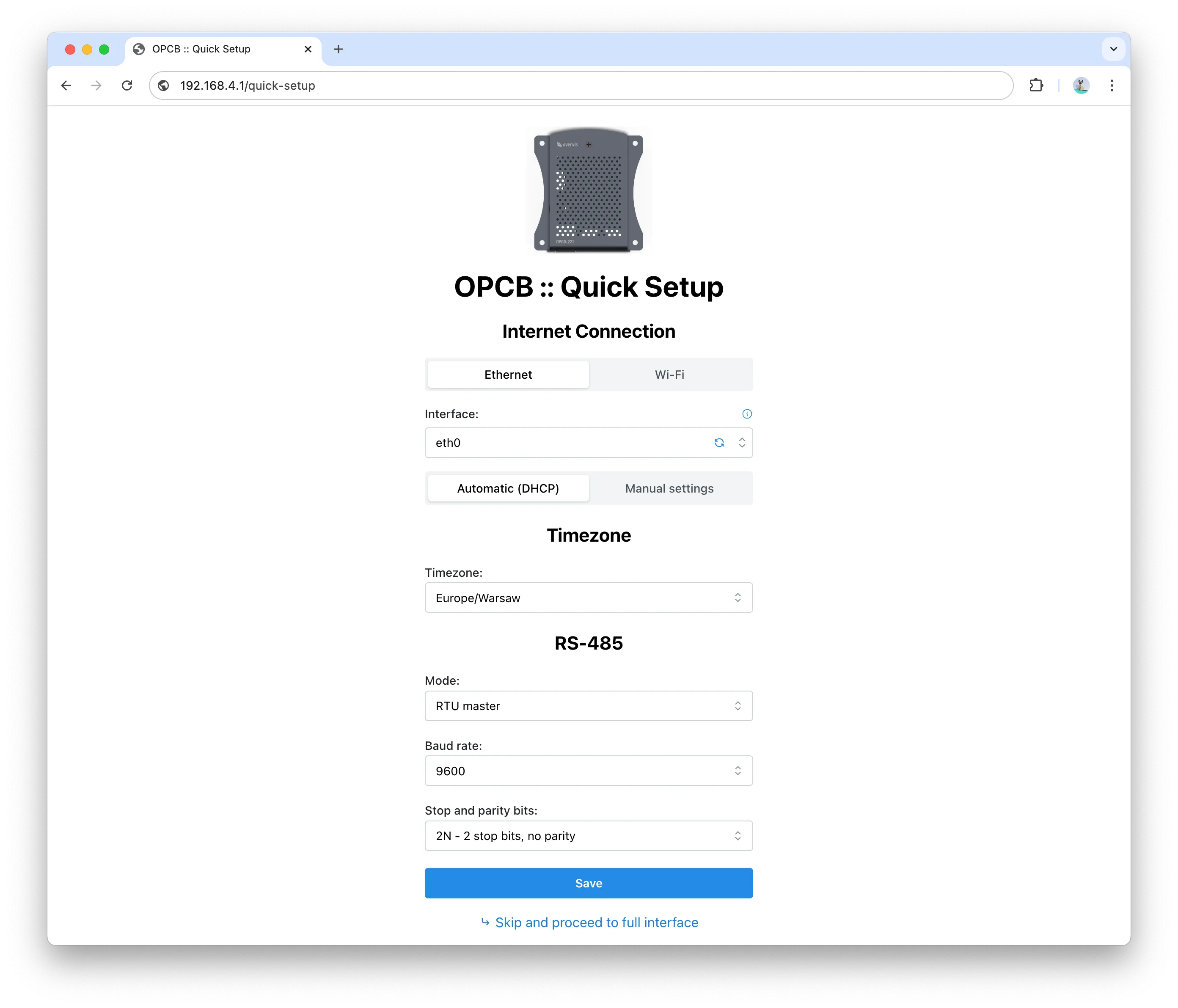
Step 3: Quick Setup
Section titled “Step 3: Quick Setup”After logging in, the quick setup page will be displayed. If the device was configured previously and reconfiguration is needed, the quick setup page can be accessed from the drop-down drawer in the header under the logo.
Step 4: Connect to Overvis Cloud
Section titled “Step 4: Connect to Overvis Cloud”After the initial setup, the device will connect to the internet using the specified settings and will be available in the Overvis cloud.
Access the link on the sticker and follow the instructions on the Overvis website to set up the device cloud operation and access the OPCB-221B interface through the Overvis cloud.
Safety Precautions
Section titled “Safety Precautions”To ensure the product’s safe operation, it is strictly forbidden to:
- Carry out installation works and maintenance without disconnecting the product from the mains
- Open and repair the product without professional help
- Operate the product with mechanical damages to the housing
Water penetration on terminals and internal elements of the product is not allowed.
During operation and maintenance, the regulatory document requirements must be met, namely:
- Regulations for Operation of Consumer Electrical Installations
- Safety Rules for Operation of Consumer Electrical Installations
- Occupational Safety in Operation of Electrical Installations
Maintenance
Section titled “Maintenance”WHEN MAINTAINING, THE PRODUCT AND DEVICES CONNECTED TO IT MUST BE DISCONNECTED FROM THE POWER SUPPLY.
Maintenance of the product should be performed by qualified technicians.
Recommended frequency of maintenance is every six months.
Procedure
Section titled “Procedure”- Check the reliability of wire connections; tighten if necessary
- Check the reliability of USB connections; fix them with plastic clamps if needed
- Visually inspect the integrity of the housing. In case of damage, take the product out of service and send it for repair
- If needed, clean the housing of the product with a dry cloth
Do not use abrasives or solvents for cleaning.
Service Life and Manufacturer Warranty
Section titled “Service Life and Manufacturer Warranty”| Parameter | Value |
|---|---|
| Service lifetime of the product | 10 years |
| Shelf life | 3 years |
| Warranty period | 3 years from the date of sale |
At the end of its service life, please contact the manufacturer.
During the warranty period (in case of failure), the manufacturer repairs the product free of charge.
Warranty service is performed at the place of purchase or by the manufacturer.
Post-warranty maintenance of the product is performed by the manufacturer at current rates.
Before sending the product for repair, it must be packed in the factory or other packaging that prevents mechanical damage.
If returning the product or submitting it for warranty (post-warranty) service, please state in detail the reason for return in the complaint information field.
Transportation and Storage
Section titled “Transportation and Storage”The product in its original packaging is permitted to be transported and stored at temperatures ranging from -45 to +60 °C and with relative humidity of no more than 80%. During transportation, the product should be protected from mechanical damage.
Manufacturer Contact Information
Section titled “Manufacturer Contact Information”NOVATEK-ELECTRO LTD.
Ukraine, 65007, Odessa, Admirala Lazareva str. 59
- Tel: +38(048)738-00-28
- Tel/Fax: +38(048)234-36-73
- Web: http://www.novatek-electro.com