MC251 Operating Manual
This Operating Manual explains the design, safety requirements, operating rules, and maintenance procedures for the Overvis MC251 RS-485 interface controller.
Safety information
Section titled “Safety information”During operation and maintenance, observe the requirements of applicable regulatory documents, including:
- Regulations for Operation of Consumer Electrical Installations;
- Safety Rules for Operation of Consumer Electrical Installations;
- Occupational Safety Rules for Operation of Electrical Installations.
Only qualified personnel who have studied this Operating Manual should perform installation, adjustment, and maintenance.
When used in accordance with this manual, the Overvis MC251 is safe in operation.
The Overvis MC251 meets the requirements of the following standards: EN 60947-1; EN 60947-6-2; EN 55011; EN 61000-4-2.
The device contains no hazardous substances in excess of maximum permissible limits.
The development and production quality management system complies with ISO 9001:2015.
General description
Section titled “General description”The Overvis MC251 is a Cloud-first programmable RS-485 to Ethernet / GSM / LTE gateway and controller. It:
- collects data from connected Modbus devices;
- transfers data to a cloud server;
- provides access to data via Modbus TCP or SMS text messages;
- tracks events and executes actions (for example, sending SMS notifications, writing values to Modbus devices, or logging values to a memory card).
The Overvis MC251 provides the following capabilities:
- Flexible connection options: Ethernet (wired) or wireless GPRS / FDD-LTE, automatic selection of the connection method to the cloud server, automatic or manual selection of GSM options and communication parameters, automatic or manual Ethernet settings
- Access security: no default password, encrypted Cloud VPN connection, passwords for setup mode and connections to the Modbus network, passwords for SMS-based device control
- Flexible RS-485 communication: Modbus RTU or ASCII, even/odd/no parity, wide range of baud rates, adjustable delays
- Programmable logic for data collection, event tracking, and actions in response to events (see Operations logic programming)
- Service functions: real-time clock, astronomical timer, diagnostic logs, automatic or manual firmware update
Front panel and indicators
Section titled “Front panel and indicators”
Fig.1 – Overall and mounting dimensions of MC251
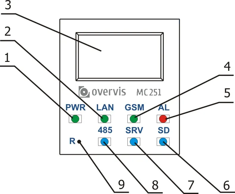
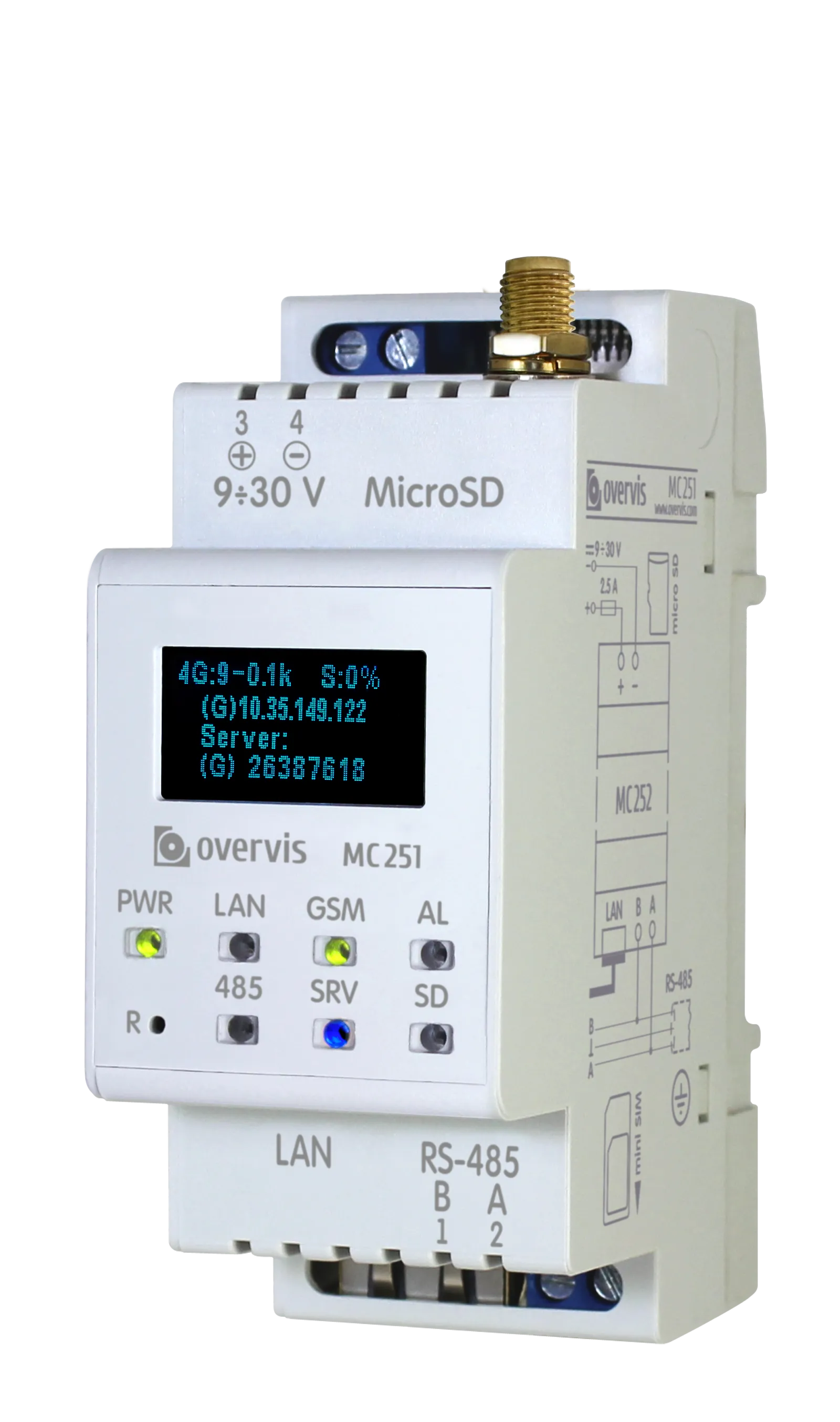
Fig.2 – Controls of the Overvis MC251
PWRLED is on when there is supply voltage;LANLED is on when connected to Ethernet network, and is blinking during the data exchange on the network;- The display shows the state of the device, active connections, device addresses, and the load of communication interfaces;
GSMLED flashes every 1.5 s when GSM (2G) communication is available; flashes 3 times per second when LTE (4G) communication is available, or when GPRS or FDD-LTE data is being exchanged;ALLED warns about the error as a result of analysis of the received data;SDis on when there is a memory card in its slot, and is blinking during the data exchange with the memory card;SRVis on when the connection is present with the Overvis Cloud VPN server, and is blinking during the data exchange via this connection;485is on when waiting for data from a device on RS-485 bus, and is blinking during the data exchange on this bus;Rservice button (accessible through a hole in the front panel, press with a thin non-conducting object) grants quick access to MC251 or resets the controller.
Operating conditions
Section titled “Operating conditions”The Overvis MC251 is designed for operation under the following environmental conditions:
- Ambient temperature: –35 … +55 °С
- Atmospheric pressure: 84 … 106.7 kPa
- Relative humidity (at +25 °С): 30 … 80%
Delivery set
Section titled “Delivery set”Table 1 – MC251 delivery set
| Item | Quantity |
|---|---|
| MC251 | 1 |
| Cable for Ethernet connection | 1 |
| GSM antenna | 1 |
| Memory card (microSD 2 GB) | 1 |
| Operation Manual | 1 |
| Packing | 1 |
Technical specifications
Section titled “Technical specifications”Table 2 – MC251 technical specifications
| Parameter | Value |
|---|---|
| DC rated supply voltage | 12 V |
| Data exchange interfaces via wired network | 10Base-T/100Base-T Ethernet, RS-485 |
| Supported Ethernet protocols | UDP, ARP, TCP |
| Data exchange interface via wireless network | GSM (900/1800), LTE (B1/B3/B5/B7/B8/B20) |
| Supported standards of wireless network | SMS, GPRS, FDD-LTE Cat.1 |
| Integrated TCP/UDP clients | Modbus TCP, HTTP, WIREGUARD, NTP, DNS |
| Integrated TCP servers | Modbus TCP, HTTP |
| Maximum number of incoming TCP connections | 4 |
| Supported Modbus protocols via RS-485 | Modbus RTU, Modbus ASCII |
| Transmission speed via RS-485 | 75 … 230400 bps |
| Maximal output voltage of driver RS-485 | 3.3 V |
| Short circuit output voltage of driver RS-485 (maximum) | 250 mA |
| Resistance of built-in terminator | 1000 Ohm |
| The recommended number of connected devices in RS-485 network: | |
| – when the input current of receivers on RS-485 bus is less than 0.125 mA; | ≤ 256 |
| – when the input current of receivers on RS-485 bus is less than 1 mA | ≤ 32 |
| Readiness time when power is applied | ≤ 15 s* |
| The supply voltage at which the operability is maintained | 9 … 30 V |
| Power consumption (under load) | ≤ 6 W |
| Device service | Switchgear and controlgear |
| Rated operating condition | Continuous |
| Protection class rating | IP20 |
| Electric shock protection class | III |
| Climatic design version | NF 3.1 |
| Overvoltage category | II |
| Rated voltage of insulation | 450 V |
| Rated impulse withstand voltage | 2.5 kV |
| Conductor cross-section for connecting to terminals | 0.5 … 3 mm² |
| Tightening torque of the terminal screws | 0.4 N·m |
| Weight | ≤ 0.400 kg |
| Overall dimensions (Fig. 1), H×W×D | 64.5 × 90.2 × 36 mm |
| Installation (mounting) of the device | On standard 35 mm DIN-rail |
| Device orientation | Operable in any position in space |
| Housing material | Self-extinguishing plastic |
* Establishing connections in Ethernet / GSM / Internet networks can take more time.
Device architecture
Section titled “Device architecture”MC251 provides monitoring and control over Modbus RTU/ASCII devices in an RS-485 network for the cloud server.
The secure VPN connection to a cloud server is established:
- via Ethernet network using an integrated Ethernet interface chip;
- via GPRS / FDD-LTE using a built-in modem (used when Ethernet connection is not available).
MC251 also provides access to RS-485 devices via Ethernet, GSM / LTE, or SMS.
In addition, MC251 can connect via the Modbus TCP protocol to exchange data with Modbus TCP devices or with another MC251 controller.
MC251 receives and processes SMS messages that contain a password and a read/write command for Modbus devices.
When you insert a memory card with prepared operation logic program files, MC251 may load this program into internal memory. This program defines data collection and event tracking. It runs in the background.
You can write collected data to the memory card in tabular or binary format. For registered events, you can configure actions such as sending SMS messages or writing corrected Modbus values.
MC251 stores network settings, security parameters, and operation logic in its built-in memory.
Installation and wiring
Section titled “Installation and wiring”Before you start:
- Unpack MC251 (we recommend keeping the original packing for the entire warranty period).
- Check MC251 for damage after transportation. If you find any damage, contact the supplier or manufacturer.
- Read this Operating Manual carefully (pay special attention to the power supply in the connection diagram).
- If you have any questions regarding installation, contact the manufacturer.
Wiring requirements
Section titled “Wiring requirements”If the temperature of MC251 after transportation or storage differs from the ambient operating temperature, keep MC251 under operating conditions for at least two hours before connecting it to the power supply. This prevents condensation on internal components.
To ensure reliable electrical connections, use flexible (stranded) wires. Strip the insulation from the wire ends by 5±0.5 mm and crimp with suitable ferrules. It is recommended to use wire with a cross-section of at least 1 mm².
- When connecting to the RS-485 bus, use twisted-pair cable of category 1 or higher. A shielded cable is recommended; in that case, ground the shield according to “ANSI/TIA/EIA-485-A-1998”.
- When connecting to Ethernet, use the supplied cable or a category 5e twisted-pair cable with an 8P8C (RJ-45) plug.
Route and fasten wires so as to avoid mechanical damage, twisting, or abrasion of the insulation.
For a reliable contact, tighten the terminal screws with the force indicated in Technical specifications.
To improve safety and reliability, it is recommended to install the fuse F1 (or its equivalent) in the MC251 supply circuit, rated for a current of no more than 2.5 A.
Electrical connection
Section titled “Electrical connection”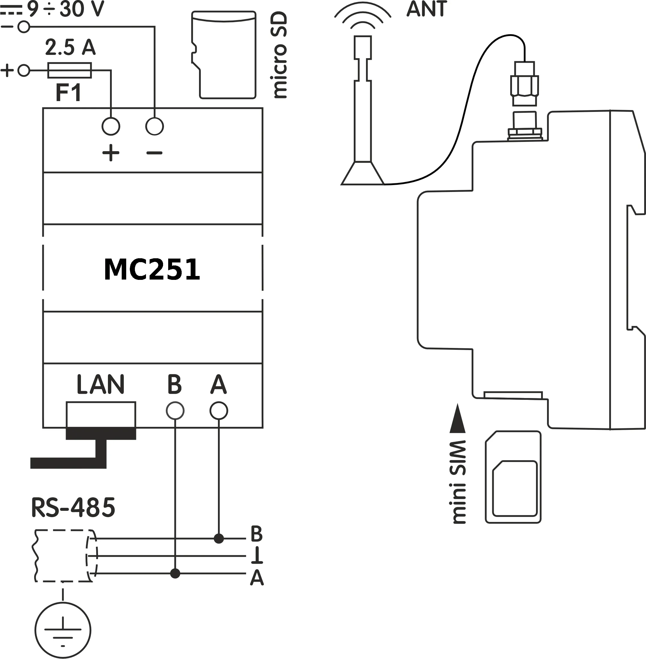
Fig.3 – Connection diagram of the device
F1– fuse (fuse element) rated for 2.5 A;- Contact
A– transmission of non-inverted signal; - Contact
B– transmission of inverted signal.
Follow these steps to connect the MC251:
- Connect the RS-485 bus cable to the
RS-485terminals (A and B) and to the RS-485 bus (or directly to the device with an RS-485 interface). - If the MC251 should connect to the Internet via wired communication, to a local network, or directly to a computer, connect the Ethernet cable to the
LANconnector and to the Ethernet network (or directly to a computer). Connection details, depending on the network type, are provided in Connections. - Connect the appropriate DC power supply to the
9÷30Vpower connector. - Insert the memory card (microSD) into the
MicroSDslot if you plan to use data logging or operation logic programming features. - If the MC251 is to connect to the Internet via wireless communication (or needs SMS exchange), insert the SIM card of the GSM operator into the
SIMslot and connect the GSM antenna to theANTconnector (SMA F connector).
Power-up and normal operation
Section titled “Power-up and normal operation”After power is turned on, all indicators except LAN and GSM light up, and MC251 performs initialization.
After approximately 2 seconds, the indicators (except for the power indicator) go out, and the device proceeds to start the communication interfaces with networks.
The display shows general information about the device (Fig. 4). Startup can take up to 15 seconds.
┌─────────────────────┐│ MC251 ││ © 2025 Overvis ││ FW Version 45 │└─────────────────────┘Fig.4 – Displaying of general information about the device on the display
After this, if enabled in settings, MC251 establishes a connection with the cloud server (or VPN) and starts executing the operation logic (if a program is loaded from the memory card). By default, cloud connections are disabled.
If configured, MC251 establishes TCP connections (via Ethernet and GSM/LTE networks) and waits for incoming TCP connections.
If a SIM card is installed, the GSM indicator shows the cellular connection status: blinking once every 1.5 seconds indicates successful network registration (but no data transfer yet); blinking 3 times per second indicates active TCP/IP data transfer via GPRS or FDD-LTE.
The display shows the interfaces load, the GSM signal strength and the IP addresses used, as shown in Figure 5.
┌─────────────────────┐│ E: 5.2к S: 15% ││ (E) 10.0.0.1 ││ │└─────────────────────┘┌─────────────────────┐│ 4G: 7-0.3к S: 15% ││ (G) 87.1.1.1 ││ │└─────────────────────┘Fig.5 – Displaying the status of connections on the display
E: 5.2k– the transmission speed via Ethernet is 5.2 kB/s;4G: 7-0.3k– the LTE signal level is 70 % and the FDD-LTE transmission rate is 0.3 kB/s;S: 15%– the load of RS-485 is 15 %.(E): 10.0.0.1– connection to the local network with the address 10.0.0.1;(G): 87.1.1.1– wireless Internet access with the address 87.1.1.1.
Communication modes
Section titled “Communication modes”The Overvis MC251 is a protocol converter that bridges RS-485 Modbus RTU/ASCII networks and TCP/IP Modbus TCP devices to be available at the cloud server. It operates in multiple communication modes simultaneously, providing flexible connectivity through Ethernet, GSM/LTE networks, and RS-485 interfaces. Each mode serves a distinct purpose and can be used independently or in combination to meet your application requirements.
Connection to cloud server (VPN connection)
Section titled “Connection to cloud server (VPN connection)”MC251 can establish and maintain a secure VPN outbound connection to a cloud server (using Wireguard protocol).
- MC251 initiates the outbound connection to the server, bypassing firewall issues
- MC251 authenticates at server and receives VPN parameters
- The VPN connection is started
- After the connection is established, MC251 operates as a Modbus TCP server in slave mode, waiting for connections and processing server requests
- The server connects to MC251 and sends Modbus requests through the VPN tunnel
- MC251 forwards these requests to RS-485 devices or responds with its own register values
- Returns responses back to the server
- If the
SRVLED is on, the connection to the server VPN has been successfully established - If the
SRVLED blinks, data is being exchanged via this connection
Use case: Centralized monitoring and control of distributed equipment through Overvis Cloud platform, enabling secure remote access from anywhere without configuring firewall port forwarding or static IP addresses.
RS-485 Modbus RTU/ASCII master mode
Section titled “RS-485 Modbus RTU/ASCII master mode”In master mode, MC251 forwards Modbus requests from TCP clients to devices on the RS-485 bus and returns their responses.
- MC251 receives Modbus requests from incoming TCP connections
- Translates Modbus TCP requests to Modbus RTU/ASCII format
- Forwards requests to target devices on the RS-485 network
- Returns responses back to the TCP client
- Supports both Modbus RTU and Modbus ASCII protocols
When an operation logic program is loaded, MC251 can also autonomously poll devices at configured intervals for data logging or event tracking purposes.
Request processing is described in detail in Modbus interface.
Use case: Data collection and event tracking for serial port equipment.
Integrated Modbus TCP server (slave mode)
Section titled “Integrated Modbus TCP server (slave mode)”MC251 acts as a Modbus TCP server, accepting incoming connections and processing Modbus requests.
- Listens for incoming TCP connections from Overvis Cloud, SCADA systems, HMI panels, or other Modbus TCP clients
- Receives Modbus TCP requests from connected clients
- Responds with its own register values or translates requests to Modbus RTU/ASCII and forwards them to RS-485 devices (in master mode)
- Returns responses back to the TCP client
- Supports up to 4 simultaneous incoming TCP connections
- MC251’s own registers can also be accessed directly (current time, supply voltage, logic calculation results, etc.)
Use case: Access to the RS-485 serial port equipment for the TCP devices, HMI panels, SCADA and other Modbus TCP software.
Connection to remote Modbus TCP servers (master mode)
Section titled “Connection to remote Modbus TCP servers (master mode)”MC251 can establish outgoing connections to remote Modbus TCP servers, enabling it to forward requests to remote devices.
- Initiates and maintains TCP connections to specified remote Modbus TCP servers via Ethernet or GSM/LTE
- Forwards Modbus requests received from other sources (some RS-485 master, incoming TCP client connections, or operation logic) to these remote servers
- Receives responses from remote servers and returns them to the requester
- Can connect to multiple remote servers simultaneously (up to 3 connections can be configured)
- Enables bridging between local RS-485 network and remote TCP-based Modbus devices
Use case: Data collection and event tracking for Modbus TCP equipment.
Reverse control translator mode (RS-485 slave, TCP master)
Section titled “Reverse control translator mode (RS-485 slave, TCP master)”MC251 can operate as an RS-485 slave while acting as a Modbus TCP master, enabling reverse control scenarios.
- Receives Modbus RTU/ASCII requests from an RS-485 master device
- Translates these requests to Modbus TCP format
- Forwards them to remote TCP servers or local TCP-based devices
- Receives responses from TCP devices
- Returns responses back to the RS-485 master in RTU/ASCII format
Use case: Access to the Modbus TCP equipment for the RS-485 serial port master device.
Tunnel mode (transparent data forwarding)
Section titled “Tunnel mode (transparent data forwarding)”In tunnel mode, MC251 accepts data “as is” (without protocol verification) and forwards it to all other directions that are configured for this mode.
This allows transmission of data in formats different from the Modbus protocol. For example, arbitrary data received via RS-485 can be redirected to a remote TCP server, and vice versa.
Tunnel mode can be configured individually for:
- Each connection to a remote TCP server
- The RS-485 interface
- Incoming connections to the Ethernet TCP port
- Incoming connections to the GSM/LTE TCP port
First, a data packet from one direction is fully received (for Ethernet or GSM/LTE, this is one TCP packet; for RS-485, the packet length is determined by the Modbus RTU maximum-pause rules). Then it is sequentially forwarded to the other tunnel directions (if there are more than two directions).
The maximum data packet length in tunnel mode is 254 bytes.
Use case: Connecting equipment with non-Modbus compatible protocols, or extending serial communication over IP networks.
Network extension (long-range RS-485 bridging)
Section titled “Network extension (long-range RS-485 bridging)”Pair two MC251 units to extend RS-485 networks beyond physical distance limitations by converting to/from TCP.
- One MC251 operates in master mode on its RS-485 interface, while the other is in slave mode
- First MC251 receives RS-485 signals and converts them to TCP packets
- Data is transmitted over any distance via 4G/LTE or Ethernet networks
- Second MC251 receives TCP packets and converts them back to RS-485 signals
- Creates a transparent bridge between two RS-485 networks or segments
- Works in both Modbus protocol mode (with address translation) and tunnel mode (fully transparent)
Use case: Connecting RS-485 networks in separate buildings without running long cable runs, extending RS-485 beyond the 1200m distance limit, or accessing remote sites via cellular networks.
Network consolidation (address space remapping)
Section titled “Network consolidation (address space remapping)”Combine multiple separate Modbus networks into one unified network by remapping device address spaces.
- Connect multiple isolated RS-485 networks, each with its own set of device addresses and/or baudrate and parity settings
- Configure address mapping to avoid conflicts (e.g., map first network’s UIDs 1-10 to 1-10, second network’s UIDs 1-10 to 11-20)
- Access all devices from a single TCP or RS-485 interface as if they were on one network
- Can combine local RS-485 devices with remote TCP devices seamlessly
Use case: Integrating multiple legacy systems with overlapping device addresses into a single SCADA system without physically re-addressing devices.
Access to Modbus network using SMS
Section titled “Access to Modbus network using SMS”If an active SIM card is installed, MC251 receives and processes incoming SMS messages.
- MC251 receives SMS messages sent to the SIM card’s phone number
- If the SMS contains a correctly formatted Modbus request, MC251 processes it:
- Forwards the request to the target device on RS-485 or TCP
- Receives the response
- Sends a reply SMS with the response data
- If the SMS is not a Modbus request, it is stored in the incoming SMS list for processing by operation logic programs
SMS Modbus request format is described in Modbus interface. Custom SMS processing is described in Operations logic programming.
Use case: Remote diagnostics and emergency control of equipment in locations without reliable internet, such as pump stations or remote substations.
Data collection and event tracking
Section titled “Data collection and event tracking”When an operation logic program is loaded into internal memory, MC251 reads specified parameters at a configured rate. These parameters may include registers of connected Modbus devices, MC251’s own registers, or MC251 memory.
The device then performs configured calculations and evaluates the received data. As a result, the following actions can be executed:
- writing the read values to a log on the memory card;
- sending SMS notifications on events;
- writing new values to parameters.
The program is loaded into internal memory from the memory card. The procedure for preparing and loading the program into the device is described in Operations logic programming.
Use case: Autonomous data logging to memory card for later analysis, or automated responses like sending alarm notifications or regulation commands when temperature exceeds thresholds.
Configuration
Section titled “Configuration”MC251 configuration can be performed in two ways:
- quick setup of the Internet connection via the web interface using a browser (see Web interfaces);
- quick setup via the Modbus protocol using any Modbus client software that works with MC251’s own registers (see Modbus interface).
- advanced configuration at the Overvis cloud server device page.
Use the R button to grant quick access to MC251, restart the controller, or reset factory settings.
Access the button through a hole on the front panel and press with a thin non-conductive object.
To reset the device to factory settings and clear the internal operation logic memory:
- Press and hold the service button
Rfor at least 8 seconds. After 2 seconds, theALindicator will light up. After 8 seconds, the settings are reset, internal memory is cleared, and the device restarts; the indicators blink once. - Release the
Rbutton.
To safely remove the memory card and restart the device (while preserving user settings):
- Press and hold the service button
Rfor 2 to 8 seconds. - When the
ALindicator lights up, release theRbutton. If needed, remove the memory card after theSDindicator turns off.
To wake up the display, show connection information, and grant quick access to the device:
- Briefly press and release the service button
R. - The display lights up and shows connection information. For several minutes, configuration access (without a password) is granted for incoming connections.
Maintenance
Section titled “Maintenance”- Only qualified personnel should perform maintenance.
- Recommended maintenance interval is every six months.
- Check the reliability of wire connections; if necessary, retighten terminals with the torque specified in Technical Specifications.
- Visually inspect the housing. If you detect cracks or other damage, take MC251 out of service and send it for repair.
- If necessary, wipe the front panel and housing with a soft cloth.
Do not use abrasives or solvents for cleaning.
Service life and warranty
Section titled “Service life and warranty”- The service life of MC251 is 10 years. After the service life expires, contact the manufacturer.
- Shelf life is 3 years.
- The warranty period is 5 years from the date of sale. During the warranty period, in the event of failure, the manufacturer provides free repair.
- The place of purchase or the manufacturer performs warranty service.
- The manufacturer performs post-warranty service at current rates.
- Before sending MC251 for repair, pack it in the original or other packaging that protects it from mechanical damage.
When returning MC251 for warranty or post-warranty service, please provide a detailed reason for the return in the claims data field.
Transportation and storage
Section titled “Transportation and storage”You may transport and store MC251 in the original package at temperatures from minus 45 to +60 °C and relative humidity of no more than 80%. When transporting MC251, protect it against mechanical damage.