Connecting Equipment
Overvis Cloud communicates with field equipment through Modbus TCP. In a typical setup, a communication controller (Modbus TCP gateway) connects to the internet and maintains a link with the Overvis server. Modbus RTU devices — temperature controllers, energy meters, PLCs, sensors — connect to the gateway via RS-485 and are accessed by Overvis through the gateway.
graph LR
    A["Modbus RTU<br/>devices"] -->|"RS-485<br/>Modbus RTU"| B["Communication<br/>controller<br/>(Modbus TCP gateway)"]
    B -->|"Internet<br/>Modbus TCP"| C["Overvis Cloud"]
    C -->|"Web / HTTPS"| D["User<br/>(browser)"]
In Overvis, this entire chain is represented as a network: one communication controller plus all the Modbus RTU devices accessible through it. Each device within a network has a unique Modbus address (unit ID) and a set of parameters — individual register values that Overvis reads from or writes to the device. For details on managing networks, devices, and parameters after connection, see Networks, Devices & Parameters.
This page covers everything needed to establish the connection: registering the gateway in Overvis, wiring RS-485 devices, configuring serial communication settings, resolving conflicts with previously registered devices, and diagnosing connection problems.
Connection Methods
Section titled “Connection Methods”Overvis supports three methods for connecting a Modbus TCP gateway to the platform. The first two (PIN code and activation code) use a reverse connection — the controller initiates an outbound TCP connection to Overvis, which avoids firewall and NAT issues. The third method (direct connection) requires Overvis to connect inbound to the controller, which needs a static public IP and port forwarding.

PIN Code
Section titled “PIN Code”The PIN code is an 8-character alphanumeric code (e.g. A1B2C3D4) printed on a sticker attached to the device. The sticker also contains a QR code that encodes a URL like https://c.overvis.com/A1B2C3D4.

This is the simplest connection method and the recommended choice for first-time setup of Overvis-compatible controllers (MC252, EM-482, EM-483, and others).
How it works:
The controller connects outbound to Overvis and identifies itself by MAC address. When the user enters the PIN code, Overvis looks up the MAC address associated with that PIN and links it to the user’s network. Since the controller initiates the connection, no port forwarding or static IP is required — the connection works through firewalls, NAT, and dynamic IP addresses.
sequenceDiagram
    participant Controller
    participant Overvis
    participant User

    Controller->>Overvis: Connect & send handshake (MAC address)
    Overvis->>Controller: Confirm handshake
    Note over Controller,Overvis: Reverse connection established, waiting for binding

    User->>Overvis: Enter PIN code on Create Network page
    Overvis->>Overvis: Look up MAC address by PIN
    Overvis->>Overvis: Bind connection to user's network
    Overvis->>User: Network created

    loop Polling
        Overvis->>Controller: Read registers (Modbus TCP)
        Controller->>Overvis: Return data
    end
Steps:
- Make sure the controller is powered on and connected to the internet (Ethernet or GSM). Verify connectivity on the device’s display or web interface.
- Locate the sticker on the device. Either scan the QR code with your phone (it opens the Create Network page with the PIN pre-filled) or note the PIN to enter it manually.
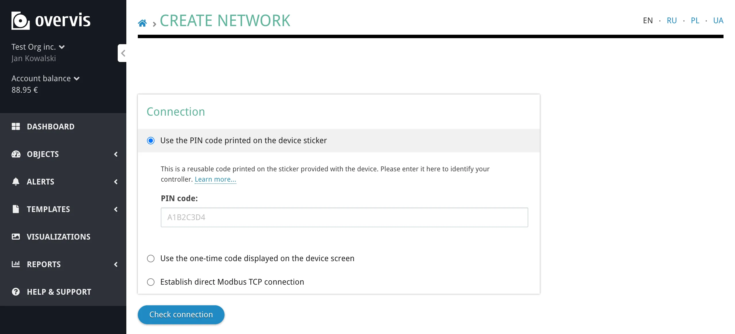
- Log in to Overvis at ocp.overvis.com and navigate to the Create Network page.
- Select Use the PIN code printed on the device sticker, enter the PIN, and click Check connection.
- If the check succeeds, Overvis confirms the controller is online and shows its details (controller model and firmware version). If it fails, verify that the controller has internet access and try again.
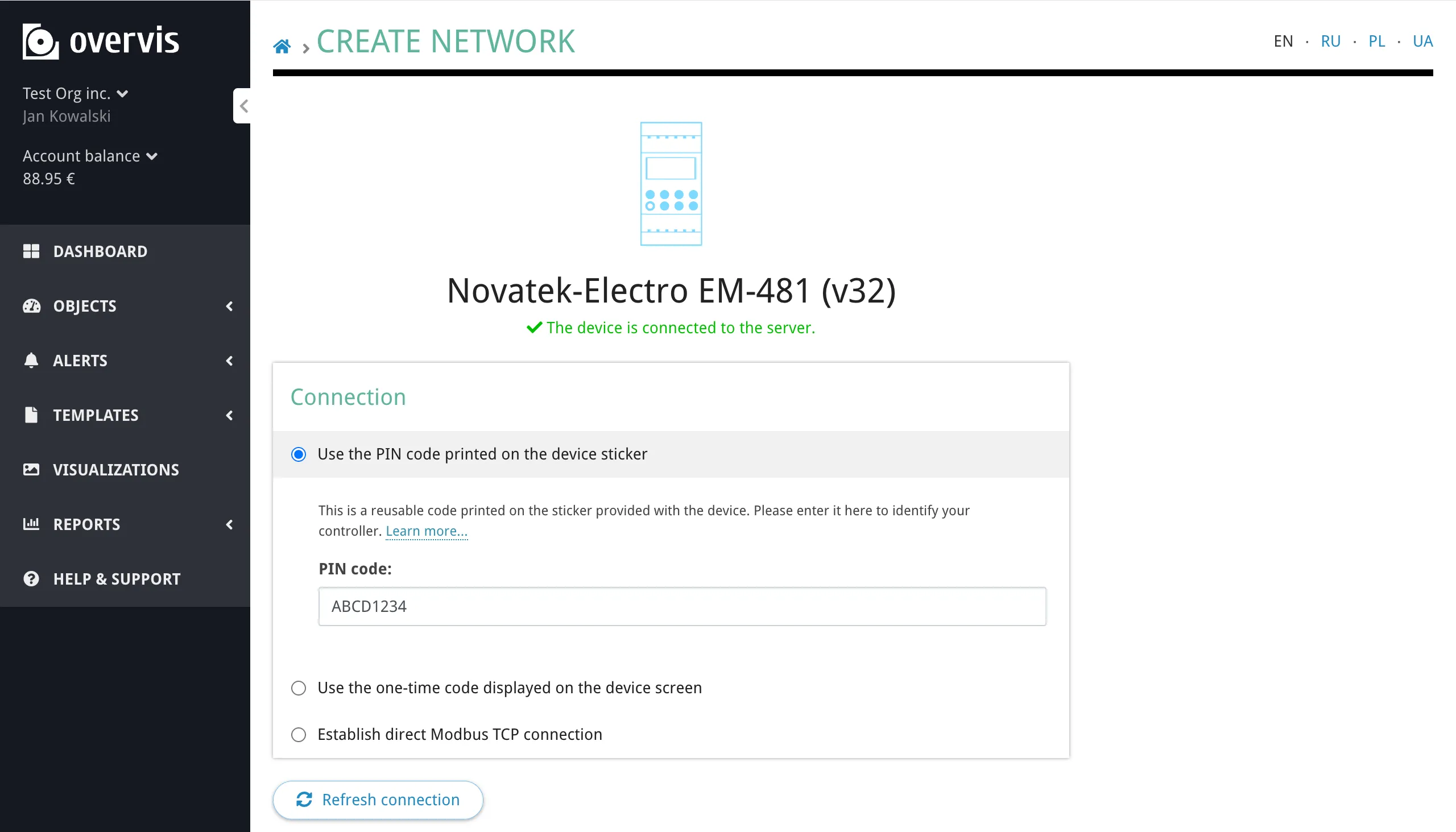
- Enter a descriptive network name and click Create network.
Important characteristics:
- The PIN code is reusable — it can be used multiple times, for example after deleting and re-creating a network.
- If the controller is already bound to a network in your account, Overvis will warn you that the existing network will be disconnected and offer to proceed. All data in the old network is preserved.
- If the controller is already bound to a network in another account, the PIN code cannot rebind it. You must use the activation code method instead (see Activation Code) or have the current owner unbind the device (see Device Conflicts and Takeover).
Activation Code
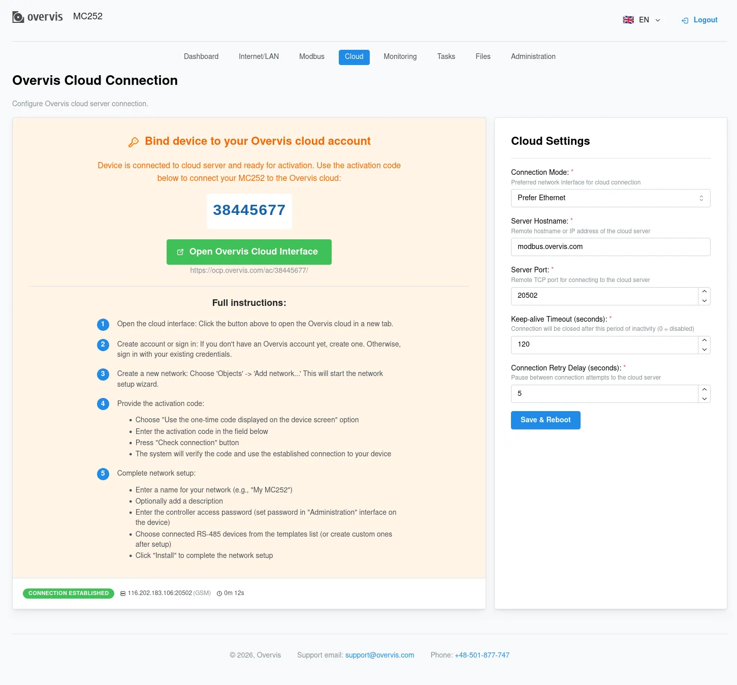
Section titled “Activation Code”The activation code is an 8-digit numeric code (e.g. 38571098) generated by the Overvis server and sent to the controller after it establishes a reverse connection. The code is displayed on the controller’s screen (if it has one) or in its local web interface.
This method is used when the PIN code sticker is unavailable, or when you need to take over a controller that is already registered under another Overvis account. Since reading the activation code requires physical or local network access to the device, it serves as proof of ownership.
How it works:
The controller connects outbound to Overvis and receives a unique activation code, which it displays on its screen or web interface. The user reads this code and enters it in Overvis to bind the device to their account. The code changes every time the controller re-establishes a connection to the server (until it is bound).
sequenceDiagram
    participant Controller
    participant Overvis
    participant User

    Controller->>Overvis: Connect & send handshake (MAC address)
    Overvis->>Overvis: Generate 8-digit activation code
    Overvis->>Controller: Send activation code
    Controller->>Controller: Display code on screen / web interface
    Note over Controller,Overvis: Reverse connection established, waiting for binding

    User->>Controller: Read activation code from display or web interface
    User->>Overvis: Enter activation code on Create Network page
    Overvis->>Overvis: Verify code, look up MAC address
    Overvis->>Overvis: Bind connection to user's network
    Overvis->>Controller: Confirm binding
    Controller->>Controller: Display "active"
    Overvis->>User: Network created

    loop Polling
        Overvis->>Controller: Read registers (Modbus TCP)
        Controller->>Overvis: Return data
    end
Steps:
-
Make sure the controller is powered on and connected to the internet.
-
Obtain the activation code:
- Controllers with a display (e.g. MC252): the 8-digit code is shown on the screen after the server connection is established. The display shows the code prefixed with
(E)for Ethernet or(G)for GSM (e.g.(E) 38571098).
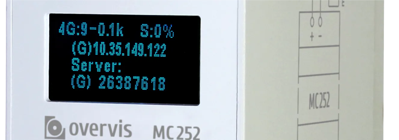
- Controllers without a display (e.g. EM-482, EM-483, EM-130): access the controller’s local web interface by its IP address. The code can be found on the status/parameters page, typically in a “Data store server activation code” or similar field.
- Controllers with a display (e.g. MC252): the 8-digit code is shown on the screen after the server connection is established. The display shows the code prefixed with
-
Log in to Overvis at ocp.overvis.com and navigate to the Create Network page.
-
Select Use the one-time code displayed on the device screen, enter the 8-digit code, and click Check connection.
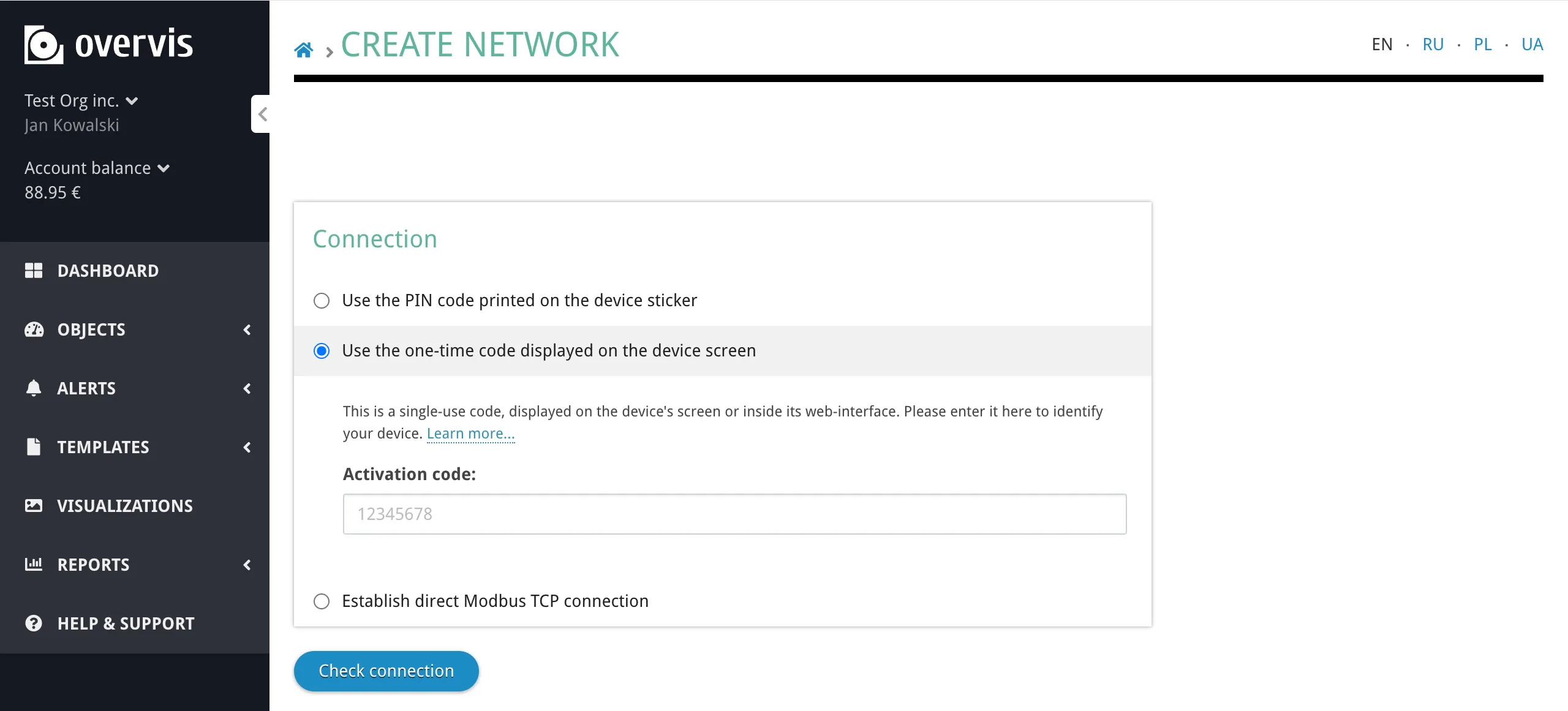
- If the check succeeds, enter a network name and click Create network.
- After successful binding, the controller’s display (MC252) will show
activeinstead of the numeric code, or the web interface status page (EM-483, EM-130) will show “Active”. The activation code stops changing — the device is now permanently bound to this network.
Important characteristics:
- The activation code has higher priority than the PIN code. It can take over a controller that is currently bound to another account, because reading the code proves physical access.
- Once bound, the controller remains associated with this network even after reconnections — Overvis will not generate a new activation code until the device is unbound.
- The activation code is single-use: each code is valid only until it is used or until the controller reconnects (which generates a new code).
Where to find the activation code by device:
| Device | Location |
|---|---|
| MC252 | Device display and web interface (Cloud tab) |
| EM-482 | Web interface, status page |
| EM-483 | Web interface, status page |
| EM-130 | Web interface, settings/parameters page (“Data store server activation code”) |
Direct Modbus TCP Connection
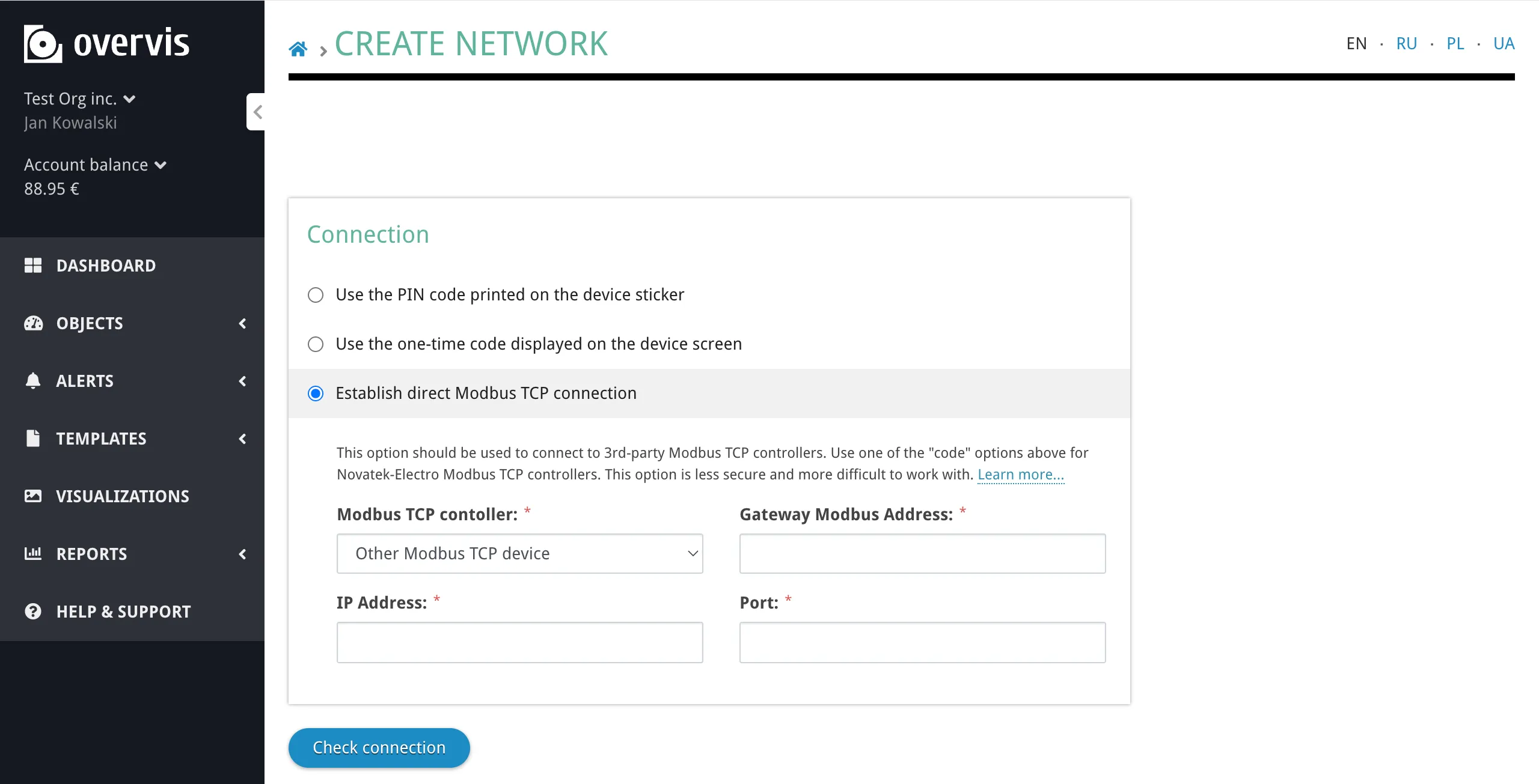
Section titled “Direct Modbus TCP Connection”With a direct connection, Overvis initiates the TCP connection to your controller by its public IP address and port. This method works with any standard Modbus TCP device — it does not require Overvis-specific firmware or integration. However, it is more complex to set up and less secure than the reverse connection methods.

How it works:
Overvis establishes a TCP connection to the specified IP address and port, then communicates using standard Modbus TCP protocol. The connection is initiated by the Overvis server, so the target device must be reachable from the internet.
sequenceDiagram
    participant User
    participant Overvis
    participant Router
    participant Controller

    User->>Overvis: Create network with direct connection<br/>(IP, port, gateway Modbus ID)
    Overvis->>Router: TCP connect to public IP:port
    Router->>Controller: Forward to controller (port forwarding)
    Controller->>Router: Modbus TCP response
    Router->>Overvis: Forward response
    Overvis->>User: Connection verified, network created

    loop Polling
        Overvis->>Router: Read registers request
        Router->>Controller: Forward to controller
        Controller->>Router: Return data
        Router->>Overvis: Forward response
    end
Prerequisites:
- Static public IP address from your ISP. Dynamic IP addresses are not supported — if your IP changes, Overvis will lose the connection.
- Port forwarding configured on your router to redirect external traffic to the controller’s local IP and Modbus TCP port (default: 502).
- DHCP reservation or static IP for the controller on your local network, so port forwarding rules remain valid.
Steps:
- Obtain a static public IP address from your ISP.
- Configure your router to forward a chosen external port to the controller’s internal IP address and Modbus TCP port (default 502).
- Ensure the controller always has the same local IP — either by configuring DHCP reservation on the router or setting a static IP on the controller.
- Log in to Overvis and navigate to the Create Network page.
- Select Establish direct Modbus TCP connection.
- Fill in the required fields:
- Modbus TCP controller — select the controller model from the dropdown, or choose “Other Modbus TCP device” for third-party equipment.
- Gateway Modbus Address — the Modbus unit ID of the gateway controller itself (default 111 for MC252; check your device’s documentation).
- IP Address — the static public IP address of your router.
- Port — the external port you configured for forwarding.
- Click Check connection to verify Overvis can reach the device.
- If the check succeeds, enter a network name and click Create network.
When to use direct connection:
- Third-party Modbus TCP devices or gateways that don’t support Overvis reverse connections.
- Devices that already have a static public IP and are set up for remote Modbus TCP access (e.g. by a SCADA system).
- Environments where the controller cannot make outbound connections to the Overvis server.
RS-485: Connecting Modbus RTU Devices
Section titled “RS-485: Connecting Modbus RTU Devices”Once a communication controller is registered in Overvis, the next step is connecting the actual field devices — temperature controllers, energy meters, PLCs, sensors, VFDs, and other Modbus RTU equipment — to the controller’s RS-485 port.
Wiring
Section titled “Wiring”RS-485 uses a differential signaling pair — two wires carrying the same signal with opposite polarity. Connect the controller and device terminals as follows:
- Controller terminal A (non-inverted, D+) → Device terminal A (D+)
- Controller terminal B (inverted, D−) → Device terminal B (D−)
- Optionally connect the shield/ground terminal (labeled
⊥,GND, orG) between devices if available.
Use shielded twisted-pair cable (Category 1 or better). Connect the shield to ground at one end of the bus according to ANSI/TIA/EIA-485-A-1998.
Bus topology:
RS-485 is a bus topology — all devices are connected in a daisy-chain (device to device), not in a star pattern. Avoid stub cables (T-shaped branches) longer than a few centimeters, as they cause signal reflections.
graph LR
    A["Controller<br/>(master)"] --- B["Device 1<br/>ID: 1"]
    B --- C["Device 2<br/>ID: 2"]
    C --- D["Device 3<br/>ID: 3"]
    D --- E["..."]
Termination:
Long RS-485 buses or buses operating at high baud rates may need termination resistors (typically 120 Ω) at both ends of the bus to reduce signal reflections. Some controllers have built-in termination (e.g. EM-482 has a 1000 Ω internal terminator). If you experience intermittent communication errors on a long bus, adding termination resistors is the first thing to try.
Serial Communication Settings
Section titled “Serial Communication Settings”All devices on the RS-485 bus must use the same serial communication settings. A mismatch in any of these parameters will prevent communication.
Baud rate — the speed of data transmission in bits per second. Common values:
| Baud rate | Typical use |
|---|---|
| 1200 | Slow/legacy devices |
| 2400 | Legacy devices |
| 4800 | Older equipment |
| 9600 | Most common default |
| 19200 | Faster polling |
| 38400 | Fast devices |
| 57600 | High-speed devices |
| 115200 | Maximum for most RS-485 devices |
The baud rate must match between the controller and all connected devices. Higher baud rates allow faster polling but may be unreliable on long cable runs or in electrically noisy environments.
Byte format (parity and stop bits):
Each byte transmitted on the RS-485 bus includes optional parity and stop bits for error detection. The byte format must match across all devices. Common options:
| Format | Description |
|---|---|
| 8N1 (ABSENT) | 8 data bits, no parity, 1 stop bit |
| 8N2 (STOP) | 8 data bits, no parity, 2 stop bits |
| 8E1 (EVEN) | 8 data bits, even parity, 1 stop bit |
| 8O1 (ODD) | 8 data bits, odd parity, 1 stop bit |
| SPACE | 8 data bits, space (zero) parity bit, 1 stop bit |
| MARK | 8 data bits, mark (one) parity bit, 1 stop bit |
| AUTO-STOP | Automatic detection — sends with 2 stop bits, accepts 1 or 2 stop bits. Available on some Overvis-compatible controllers. |
The most common configurations are 9600 baud, 8N1 or 9600 baud, 8E1. Check your device’s documentation for the required settings.
Configuring serial settings on Overvis-compatible controllers:
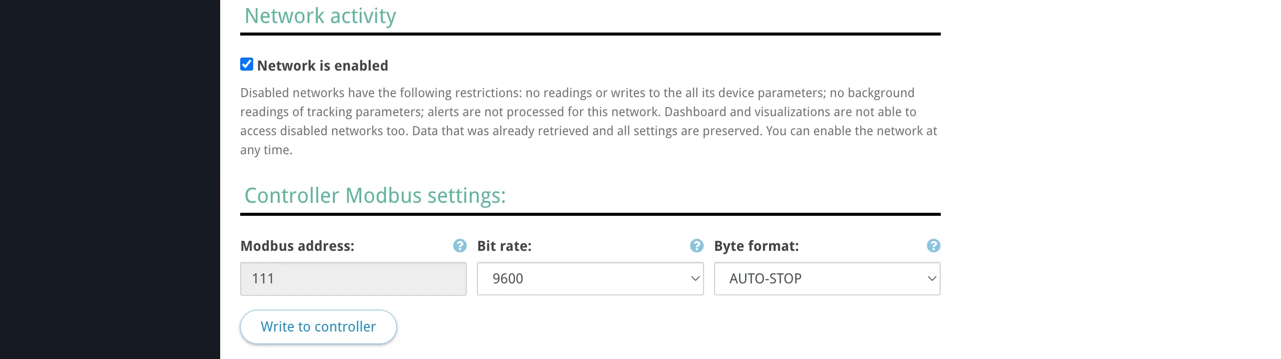
For controllers connected via reverse connection (PIN or activation code), Overvis can read and write the RS-485 serial settings remotely. After creating the network, the network settings page shows the current Bit rate and Byte format of the controller, and allows you to change them.
For third-party controllers connected via direct connection, configure the serial settings through the controller’s own interface (web interface, front panel, DIP switches, etc.).
Bus Length and Device Count
Section titled “Bus Length and Device Count”Maximum cable length:
The RS-485 standard (ANSI/TIA/EIA-485-A) specifies a maximum bus length of 1200 meters (4000 feet). In practice, the achievable distance depends on the baud rate, cable quality, and electrical noise environment:
| Baud rate | Practical max distance |
|---|---|
| 9600 | up to 1200 m |
| 19200 | up to 1200 m |
| 38400 | up to 1000 m |
| 57600 | up to 700 m |
| 115200 | up to 500 m |
These are approximate values. Use shorter runs in electrically noisy environments (near VFDs, high-voltage lines, welding equipment). If you need to extend beyond 1200 m, use RS-485 repeaters or a second communication controller with its own Overvis network.
Maximum device count:
The number of devices on a single RS-485 bus depends on the receiver input impedance of the devices:
| Receiver input current | Max devices |
|---|---|
| 1 mA (standard) | 32 |
| 0.5 mA (1/2 unit load) | 64 |
| 0.25 mA (1/4 unit load) | 128 |
| 0.125 mA (1/8 unit load) | 256 |
Most modern Modbus RTU devices use 1/4 or 1/8 unit load receivers, allowing 128–256 devices on a single bus. Check the RS-485 transceiver specifications in your devices’ datasheets.
Each device must have a unique Modbus address (unit ID) in the range 0–255. Address 0 is reserved for broadcast in the Modbus protocol (writes to all devices, no response expected).
Modbus RTU and ASCII
Section titled “Modbus RTU and ASCII”Modbus over RS-485 supports two framing modes:
- Modbus RTU — binary framing with CRC-16 error checking. This is the standard mode used by the vast majority of devices. Data is compact and transmission is efficient.
- Modbus ASCII — ASCII-encoded framing with LRC error checking. Each byte is transmitted as two ASCII hex characters, making the data human-readable but doubling the bandwidth requirement. Used by some older or specialized devices.
Both modes use the same register model and function codes — the difference is only in how bytes are encoded on the wire.
Most Overvis-compatible controllers default to Modbus RTU. If your connected device requires Modbus ASCII, configure this in the controller’s serial port settings (web interface or via Modbus registers). Overvis itself communicates with the controller using Modbus TCP, which is mode-agnostic — the controller handles the RTU/ASCII translation on the RS-485 side.
Devices in Overvis
Section titled “Devices in Overvis”Each physical Modbus RTU device connected to the controller’s RS-485 port is represented as a device in Overvis, identified by its Modbus unit ID within the network.
To add a device, open the network page in Overvis and click Add Device. Specify the device name, Modbus ID, and optionally select a device template to pre-configure all parameters. If no template is available, you can add parameters manually by specifying register addresses, data types, and names.
Information about your device’s Modbus register map, supported function codes, and data types is typically found in the device’s documentation or datasheet, usually in a section titled “Modbus registers”, “Communication protocol”, or “Register map”.
For full details on adding and configuring devices and parameters, see Networks, Devices & Parameters.
Device Conflicts and Takeover
Section titled “Device Conflicts and Takeover”When you try to create a network using a controller that is already registered in Overvis, the behavior depends on which connection method you use and whether the controller belongs to your account or another account.
PIN code: same account
Section titled “PIN code: same account”If the PIN code is already bound to a network in your account, Overvis shows a warning:
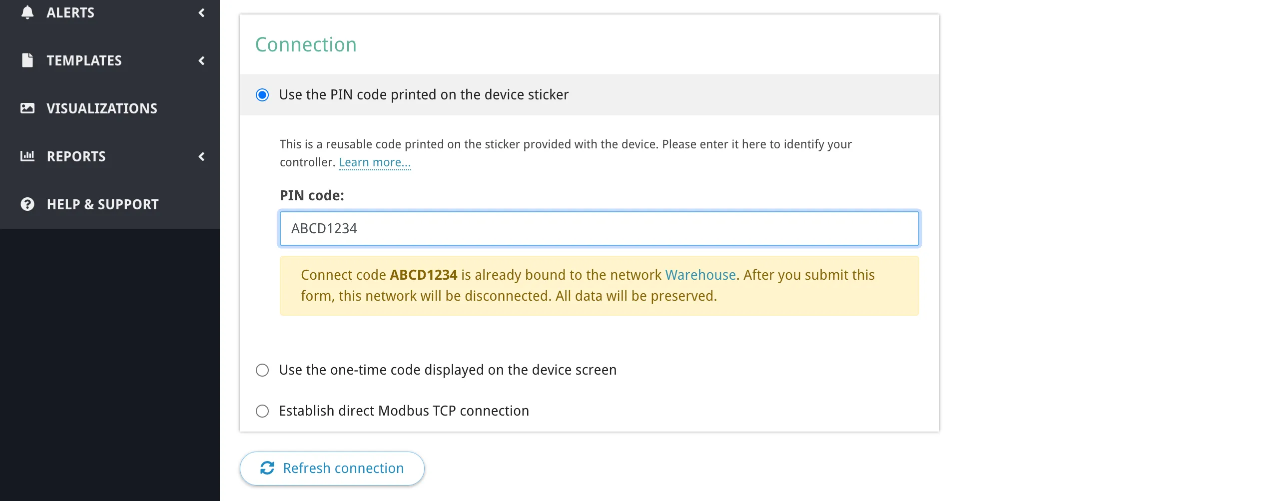
Connect code ABCD1234 is already bound to the network Warehouse. After you submit this form, this network will be disconnected. All data will be preserved.
You can proceed — the old network will be disconnected and the controller will be bound to the new network. The old network and its data (device parameters, readings history) remain accessible.
PIN code: another account
Section titled “PIN code: another account”If the controller is already bound to a network in another Overvis account, the PIN code cannot rebind it. The PIN code has lower priority — it proves that you have the sticker, but not necessarily physical access to the device.
To take over the controller, use the activation code method instead.
Activation code: takeover
Section titled “Activation code: takeover”The activation code has higher priority than the PIN code because it requires reading a code from the device’s display or web interface, which proves physical access. An activation code can take over a controller from any account — after binding, the device is removed from the previous owner’s network.
Unbinding a controller
Section titled “Unbinding a controller”To unbind a controller from its current network (so it can be registered again, either by you or another user), use any of the following methods:
- Delete the network in Overvis that the controller is bound to.
- Change the network’s connection settings to a different connection method (e.g. switch from reverse connection to direct connection).
- Reset activation on the device — access the controller’s web interface and click the “Restart Activation” (MC252, EM-483) or “Reset Activation Code” (EM-130) button. This removes the device from the Overvis network and generates a new activation code.
After unbinding, the controller re-connects to Overvis and receives a new activation code, ready for re-registration.
Advanced Network Settings
Section titled “Advanced Network Settings”The network creation and settings page includes an Advanced settings section with options that affect how Overvis communicates with the controller.
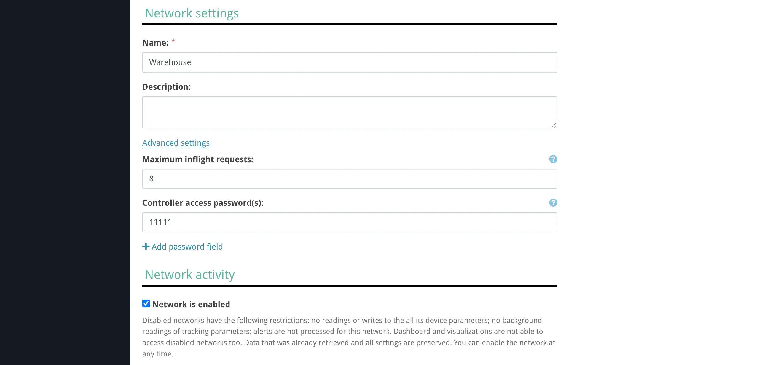
Controller access passwords
Section titled “Controller access passwords”Some controllers support password-based access protection for reading and/or writing registers. If your controller has passwords configured, add them in the Controller access password(s) section. Overvis sends these passwords to the controller after connecting, exactly as entered.
You can add multiple passwords — for example, separate read and write passwords. The controller determines which level of access each password grants.
Maximum inflight requests
Section titled “Maximum inflight requests”Controls how many Modbus requests Overvis sends to this network simultaneously (in parallel). The default is 1 — Overvis waits for each response before sending the next request (sequential mode).
Increasing this value allows Overvis to send multiple requests at once, which can speed up polling when the controller supports it. However, many RS-485 controllers process requests sequentially on the serial bus regardless, so setting a high value may not improve performance and can cause timeouts if the controller’s request queue overflows.
Use the default value of 1 unless you know your controller supports parallel request processing.
Network enabled/disabled
Section titled “Network enabled/disabled”Networks can be disabled to pause all communication without deleting the network or losing data. A disabled network stops all readings, writes, background tracking, and alert processing. Dashboard and visualizations cannot access disabled networks. All existing data and settings are preserved, and the network can be re-enabled at any time.
For more details on network management, see Networks, Devices & Parameters.
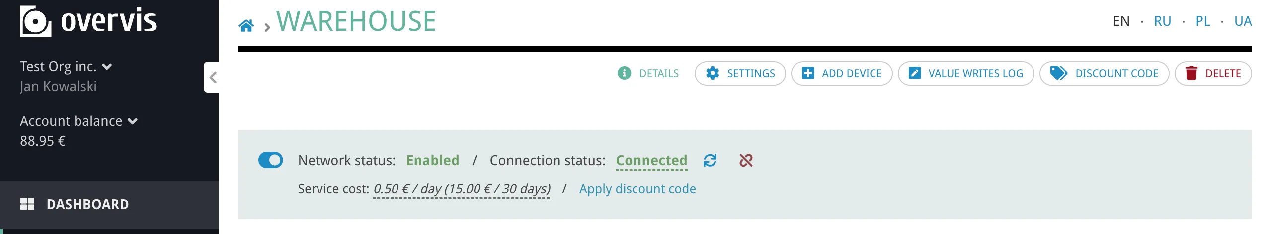
Connection Status
Section titled “Connection Status”After creating a network, the network page shows the live connection status of the gateway controller. The status indicator shows one of the following states:
- Connected — the controller is online and communicating with Overvis. A tooltip shows the connection time (“since …”).
- Disconnected — the controller is not reachable. A tooltip shows the last seen time and the disconnect reason:
- “The device has not established a connection to the server” — for reverse connections (PIN/activation code), the controller has not connected outbound to Overvis.
- “Server can’t establish the connection (timeout)” — for direct connections, Overvis tried to connect to the controller’s IP but timed out.
- “No direct connection” — no direct connection configuration is active.
Troubleshooting
Section titled “Troubleshooting”Connection problems fall into three tiers. Start at the top and work down — each tier builds on the previous one being resolved.
graph TD
    A["Data access issue"] --> B{"Is the gateway<br/>online in Overvis?"}
    B -->|No| C["Tier 1:<br/>Gateway not reachable"]
    B -->|Yes| D{"Does the device<br/>respond to reads?"}
    D -->|No| E["Tier 2:<br/>Device not reachable"]
    D -->|Yes| F{"Is the data<br/>correct?"}
    F -->|No| G["Tier 3:<br/>Data is wrong"]
    F -->|Yes| H["Out of scope <br/>of this guide"]
Tier 1: Gateway Not Reachable
Section titled “Tier 1: Gateway Not Reachable”Symptom: The network shows as offline in Overvis. No data is being read from any device. The connection status shows “The device has not established a connection to the server” (reverse connections) or “Server can’t establish the connection (timeout)” (direct connections).
This means Overvis cannot communicate with the communication controller. For reverse connections, it means the controller has not established or has lost its outbound connection to Overvis. For direct connections, it means Overvis cannot reach the controller’s IP and port.
Reverse connections (PIN / activation code)
Section titled “Reverse connections (PIN / activation code)”1. Power and basic indicators
Verify the controller is powered on and running. Check the power indicator:
| Device | Normal power indicator |
|---|---|
| MC252 | PWR LED stays on; display shows IP addresses |
| EM-482 | PWR LED stays green |
| EM-483 | Power LED on; error indicator (⚠) off |
| EM-130 | On/Off indicator on |
If the MC252 PWR LED does not light up, check the 9–30V DC power supply and fuse. If the EM-482 PWR indicator is constantly red or blinking fast in red, the device may be malfunctioning — contact the manufacturer. If the EM-483 error indicator (⚠) is red steady or periodic after power-on, the device has a fault.
2. Network connection (Ethernet / Wi-Fi)
The controller must have a working link to the local network before it can reach Overvis.
- MC252 (Ethernet): Check that the Ethernet cable is connected and the
LANLED is active (blinking during data transfer). The display shows the assigned IP prefixed with(E). If the display shows(E) 0.0.0.0, DHCP is still negotiating — wait 20–60 seconds. If it shows(E) 192.168.0.111, DHCP failed and the device fell back to its factory default static IP. Verify the cable, router DHCP, or configure a static IP in the web interface (LAN/Internet tab). - EM-482 (Wi-Fi): The
WI-FILED blinks slowly (every 3 seconds) while connecting and turns on steady once connected. If theWI-FILED keeps blinking for more than 2 minutes, the configured Wi-Fi access point is unavailable — check the SSID, password, access point distance, and that the access point is powered on. If theWI-FIandSRVLEDs are blinking alternately, the device is in Wi-Fi setup mode — either complete the configuration via its web interface, or exit setup mode by pressing theRbutton for about 3 seconds. - EM-130 (Wi-Fi): The device must be in Wi-Fi Client mode with the Overvis client enabled. If Wi-Fi is disabled or in Access Point mode, it will not connect to the internet. Configure Wi-Fi client mode through the device’s web interface.
3. Internet access and Overvis server connection
Even with a local network link, the controller must be able to reach the Overvis server over the internet.
- MC252: Check whether the
SRVLED is on — it indicates the cloud/server connection is active. In the web interface (Cloud tab), verify the cloud connection is enabled and the server address is correct (default:ocp.overvis.com, port20502). - EM-482: The
SRVLED should turn on shortly after theWI-FILED. IfSRVremains off for more than 2 minutes, the device cannot reach the internet. Verify the server connection address in the web interface. Check that your network firewall is not blocking outgoing connections. - EM-130: In the web interface remote access settings, verify the Overvis client is enabled (“Overvis turning on” = Yes) and the server address is correct (default:
modbus.overvis.com, port20502).
4. Firewall and port requirements
The controller initiates an outbound TCP connection to the Overvis server on port 20502. Corporate networks and firewalls may block this. Ask your network administrator to allow outbound TCP traffic to ocp.overvis.com:20502 (or modbus.overvis.com:20502 for EM-130).
5. DNS resolution
The controller needs to resolve the Overvis server hostname. If DNS is not working on the local network, configure a public DNS server (e.g. 8.8.8.8) on the controller. The EM-130 uses 208.67.222.222 and 8.8.8.8 as default DNS servers.
6. GSM/LTE connection (MC252)
For controllers using cellular connectivity:
- Verify the SIM card is fully inserted (until you hear a click) and has active data service.
- Check the antenna is attached to the
ANTconnector. - Check GSM signal strength on the MC252 display (should be >0%).
- In the web interface (LAN/Internet tab → GSM section), verify the APN settings match your mobile operator’s requirements.
- If the SIM has a PIN lock, enter it in the GSM settings. If in doubt, try disabling the SIM PIN on a phone first.
- Try relocating the antenna for better signal.
7. Cloud connection not enabled on the controller
Some controllers ship with the cloud connection disabled by default:
- MC252: In the web interface, open the Cloud tab and verify the cloud connection is enabled. Click “Save & Reset” after enabling it.
- EM-130: The Overvis client is disabled by default. Enable it in the remote access settings of the web interface.
- EM-482, EM-483: The cloud connection is enabled by default. If it has been disabled, re-enable it in the web interface.
Direct connections
Section titled “Direct connections”- Static IP — verify your public IP has not changed. Check with your ISP or visit a “What is my IP” site from the controller’s network.
- Port forwarding — verify the router’s port forwarding rule is still active and points to the correct internal IP and port (default Modbus TCP port: 502).
- Controller’s local IP — has the controller’s local IP changed (DHCP lease expired)? Re-configure DHCP reservation or use a static IP on the controller.
- Firewall — verify no firewall between Overvis and the router is blocking the configured port.
- Controller — verify the controller is powered, running, and its Modbus TCP service is active on the expected port. On the MC252, check the Modbus tab in the web interface to confirm Modbus TCP Server is enabled on port 502.
Tier 2: Device Not Reachable Through Gateway
Section titled “Tier 2: Device Not Reachable Through Gateway”Symptom: The network is online (gateway is connected), but one or more devices show read errors, timeouts, or “no response” for all parameters.
The controller can talk to Overvis, but cannot communicate with the end device on the RS-485 bus.
1. Verify Modbus address
Check that the device’s Modbus address (unit ID) in Overvis matches the address configured on the physical device. The address is typically set via DIP switches, front panel, or device configuration software. Common default addresses vary by manufacturer — check the device manual.
2. Check RS-485 wiring polarity
Swap the A and B wires at the controller or at the device. Reversed polarity is the single most common RS-485 problem and does not cause equipment damage. Different manufacturers label terminals inconsistently — what one calls “A” another may call “B”. Look for D+/D- or +/- labels as a more reliable guide.
3. Match serial communication settings
All devices on the RS-485 bus must share identical serial settings. A mismatch in any parameter causes complete silence (no responses at all) or CRC errors:
- Baud rate — verify the baud rate configured on the controller matches the device’s baud rate. The most common default is 9600.
- Parity / stop bits — verify the byte format (e.g. 8N1 vs 8E1) matches between the controller and all devices. If unsure, try AUTO-STOP parity mode on controllers that support it (MC252, EM-482) — it sends with 2 stop bits and accepts 1 or 2 stop bits.
- Modbus RTU vs ASCII — the vast majority of devices use RTU mode. If your device requires ASCII mode, configure the controller accordingly.
For Overvis-compatible controllers, these settings can be changed through:
- MC252: Web interface (Modbus tab → RS-485 section), or remotely via Overvis network settings.
- EM-482: Web interface during setup, or remotely via Overvis network settings.
4. Use the MC252 device search tool
The MC252 web interface has a built-in Search Devices tool (Modbus tab → Search Devices button) that scans all Modbus addresses and optionally tries different baud rates, parity, and protocol settings. This can identify connected devices and their actual configuration. A thorough search takes 30–60 minutes; use the Fast search option if you know all devices use the same settings.
5. Use the MC252 Send Request tool
The MC252 web interface has a Send Request tool (Modbus tab → Send Request button) that sends a single Modbus request and shows the raw response. Use it to test communication with a specific device address and verify the response. An exception code in the response does not necessarily indicate a device problem — it may just mean the device doesn’t have the requested register.
6. Check cable and bus topology
- Check for damaged cable, loose terminal connections, or broken wires.
- RS-485 must be wired in a daisy-chain (bus topology), not in a star pattern. Avoid stub cables (T-shaped branches) longer than a few centimeters.
- On long buses (>100 m) or at high baud rates (>38400), add 120 Ω termination resistors at both ends of the bus. Note that the EM-482 has a built-in 1000 Ω internal terminator.
- Try a shorter cable as a test to rule out cable issues.
7. Verify device power and state
Make sure the device is powered on and in normal operating mode (not in a configuration, firmware update, or error state). Some devices disable Modbus communication during certain modes.
8. Check for bus conflicts
- Verify no two devices on the same RS-485 bus share the same Modbus address. Duplicate addresses cause collisions and garbled responses.
- If you are near the device limit for your transceiver type (32 for standard 1 mA receivers, 128–256 for low-power receivers), try disconnecting some devices to see if communication improves.
9. Electrical noise
RS-485 communication can be disrupted by nearby variable-frequency drives (VFDs), motors, high-voltage switching, or welding equipment. Route RS-485 cables away from power lines and use shielded twisted-pair cable. Connect the cable shield to ground at one end of the bus.
Tier 3: Device Reachable but Data Is Wrong
Section titled “Tier 3: Device Reachable but Data Is Wrong”Symptom: The device responds, but the values shown in Overvis are incorrect — wrong numbers, always zero, negative values when positive are expected, etc.
The communication path works, but the parameter configuration does not match the device’s register map.
1. Register address offset
Modbus register addressing conventions vary between manufacturers. Some device manuals document addresses starting from 0, others from 1, and some from 40001 (the Modicon convention, where 40001 = holding register 0). If your value is off by one register or consistently shifted, try adjusting the register address by ±1.
2. Register type mismatch
Modbus defines four register types. Using the wrong type reads from a different address space:
| Register type | Function codes | Typical use |
|---|---|---|
| Holding registers | 3 (read), 6/16 (write) | Read/write configuration and data |
| Input registers | 4 (read) | Read-only measurements |
| Coils | 1 (read), 5/15 (write) | Single-bit on/off states |
| Discrete inputs | 2 (read) | Single-bit read-only states |
Verify the parameter in Overvis uses the same register type as specified in the device documentation.
3. Data type and byte order
A temperature reading stored as a 32-bit float will appear as garbage if read as two independent 16-bit integers. Common data types:
- 16-bit unsigned integer (1 register)
- 16-bit signed integer (1 register)
- 32-bit float, IEEE 754 (2 registers)
- 32-bit unsigned/signed integer (2 registers)
For multi-register values, check both byte order (big-endian vs little-endian) and word order (AB CD vs CD AB). The MC252 Send Request tool in the web interface can help identify the correct interpretation by showing raw register values.
4. Scaling factor
Many devices store values with an implicit decimal point. For example, a temperature of 23.5°C may be stored as the integer 235 (×10) or 2350 (×100). The EM-130, for instance, represents all decimal values as integers with a conversion factor determined by the number of decimal places (1 decimal place = ×10, 2 = ×100, 3 = ×1000). Check the device documentation for the scaling factor.
5. Consult the device documentation
The device’s Modbus register map is the authoritative source for addresses, types, and scaling. It is usually found in the device manual, a separate “communication protocol” document, or on the manufacturer’s website. For Overvis-compatible devices, the register maps are available in the device documentation:
Common Overvis Error Messages
Section titled “Common Overvis Error Messages”When creating a network or checking the connection, Overvis may display these error messages:
| Error message | Meaning | What to do |
|---|---|---|
| ”Invalid PIN code.” | The entered PIN code was not found in the system. | Verify you entered the exact code from the device sticker. Check for look-alike characters (O vs 0, I vs 1). |
| ”PIN code is already used under other account.” | The controller is bound to a network in another Overvis account. The PIN code cannot override this. | Use the activation code method instead, which proves physical access and can take over the device. |
| ”Device is unreachable.” | The controller has not established a connection to Overvis. The PIN code is valid, but the device is offline. | Check that the controller is powered on and has internet access. See Tier 1 troubleshooting. |
| ”Invalid activation code.” | The entered activation code does not match any active code on the server. | The code changes every time the controller reconnects. Read the current code from the device display or web interface and enter it promptly. |
| ”Server can’t establish the connection (timeout)“ | For direct connections, Overvis could not reach the specified IP and port. | Verify the IP address, port, port forwarding, and that the controller’s Modbus TCP service is running. See Tier 1 — Direct connections. |
Controller-Specific Indicators
Section titled “Controller-Specific Indicators”Use the controller’s LEDs and display to diagnose the connection state without accessing Overvis.
| Indicator | Normal state | Problem state |
|---|---|---|
PWR | On (power OK) | Off — no power |
LAN | On/blinking (Ethernet active) | Off — no cable or link |
GSM | Slow blink every 1.5s (registered); fast blink 3x/s (TCP link active) | Off — no SIM, no signal, wrong APN |
SRV | On (cloud connection active) | Off — no internet or cloud disabled |
485 | Blinking during RS-485 communication | Off — no RS-485 traffic |
| Display | (E) or (G) + IP address | (E) 0.0.0.0 — DHCP pending; (E) 192.168.0.111 — DHCP failed |
EM-482
Section titled “EM-482”| Indicator | Normal state | Problem state |
|---|---|---|
PWR | Green (power OK) | Constant red or fast red blink — device malfunction |
WI-FI | On steady (connected) | Slow blink every 3s (>2 min) — access point unavailable |
SRV | On (server connected) | Off (>2 min) — no internet or wrong server address |
WI-FI + SRV alternating | — | Device is in Wi-Fi setup mode |
EM-483
Section titled “EM-483”| Indicator | Normal state | Problem state |
|---|---|---|
| Power | On | Off — no power |
⚠ (error) | Off | Red steady/periodic — device fault |
485 | Blinking during RS-485 activity | Off — no RS-485 traffic |
LAN | On (network active) | Off — no Ethernet link |
The EM-483 web interface status page shows the server connection state: the activation code (waiting for binding), “Active” (bound to Overvis), or “No Code” (registered via QR/PIN sticker).
EM-130
Section titled “EM-130”The EM-130 has a single On/Off indicator and a Wi-Fi button — no display. Diagnose connection state through the web interface. In the remote access settings, check that the Overvis client is enabled and the activation code is shown (indicating the server connection is established).