Getting Started
Overvis Cloud is an industrial IoT platform for remote monitoring and control of equipment via the Modbus protocol. It connects your field devices — temperature controllers, energy meters, PLCs, sensors — to the cloud, giving you real-time data access, historical logging, alerts, and remote control from anywhere with a web browser.
The guide is intended for engineers, integrators, and automation enthusiasts who are familiar with Modbus and industrial equipment, but new to the Overvis platform. For detailed connection troubleshooting and alternative connection methods, see Connecting Equipment. For platform features like alerts, visualizations, and reports, see the Overvis Cloud documentation.
What You Need
Section titled “What You Need”To follow this guide, you will need:
- A Modbus TCP communication controller — acts as a gateway between your Modbus RTU devices and the internet. We recommend the Overvis MC252 for the simplest setup experience. Other Overvis-compatible controllers are available at overvis.com/equipment.
- A Modbus RTU device — the equipment you want to monitor or control (e.g. a temperature controller, energy meter, PLC, sensor). This device connects to the communication controller via RS-485.
- RS-485 cable — a twisted pair cable to connect the Modbus RTU device to the controller’s RS-485 port.
- Internet connection — Ethernet cable or cellular network (SIM card) for the communication controller.
- A computer or smartphone — with a web browser to access Overvis Cloud.
You may also need:
- Power supply for the communication controller (refer to the controller’s documentation for voltage and connector specifications).
- Modbus device documentation — the register map, Modbus address, and communication settings of your RTU device. You will need these to configure parameters in Overvis.
Step 1: Connect the Controller to the Internet
Section titled “Step 1: Connect the Controller to the Internet”Before you can register a controller in Overvis, it must be powered on and connected to the internet.
The steps below are for the Overvis MC252. Other Overvis-compatible controllers with a PIN code label follow a similar process — for specifics, refer to the controller’s manual.
- Mount the device and connect a 12V DC power supply (9–30V range supported).
- Connect an Ethernet cable to the
LANport, or insert a SIM card with data service into theSIMslot and attach the GSM antenna. - Apply power. The device initializes in about 15 seconds.
- Press the
Rbutton to wake the display. It shows the current IP address prefixed with(E)for Ethernet or(G)for GSM, along with connection data rates.
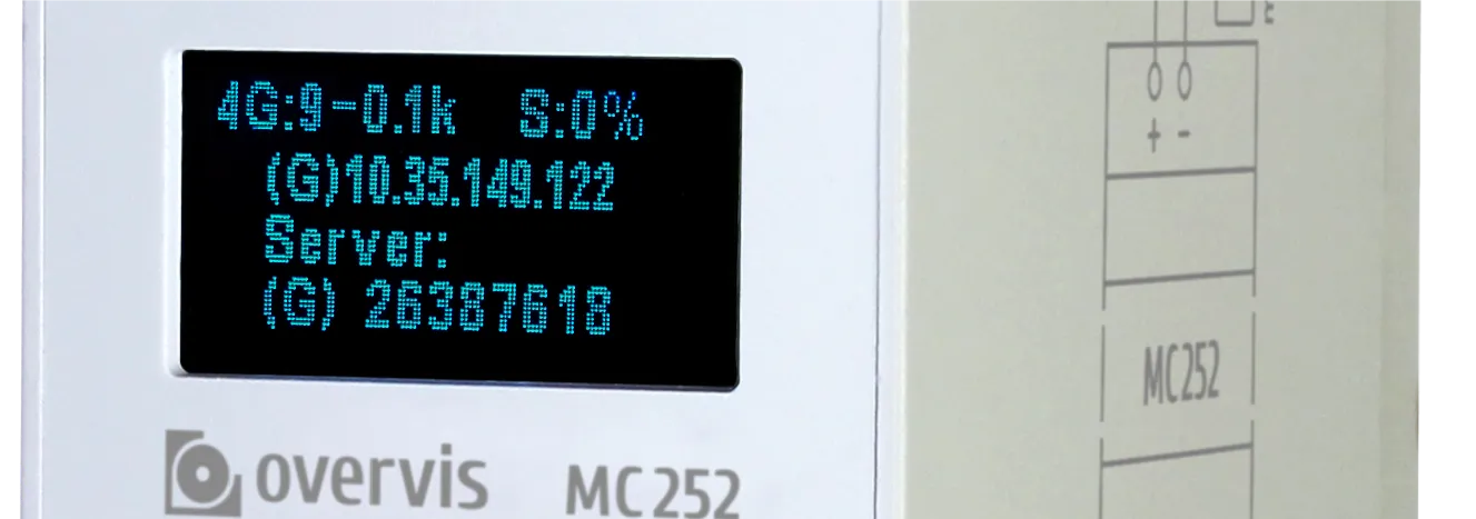
The controller uses DHCP by default, so in most cases it obtains an IP address automatically after plugging in the Ethernet cable. With a SIM card (no PIN lock), cellular connection is typically established within a minute without any user action.
If the display shows 0.0.0.0, the device has not yet obtained an address — check the cable connection or SIM card. For detailed setup instructions and troubleshooting, see the MC252 Quick Start Guide.
Step 2: Create an Overvis Account
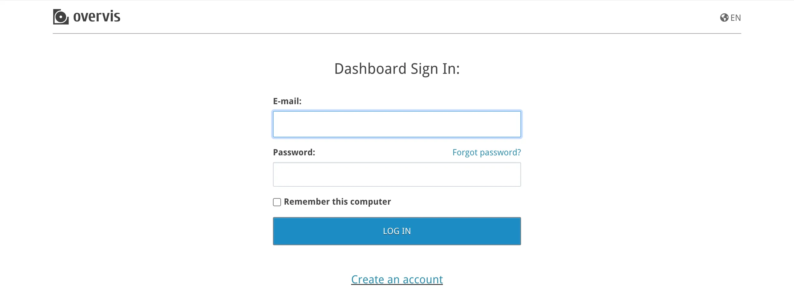
Section titled “Step 2: Create an Overvis Account”Go to ocp.overvis.com and click Create account.
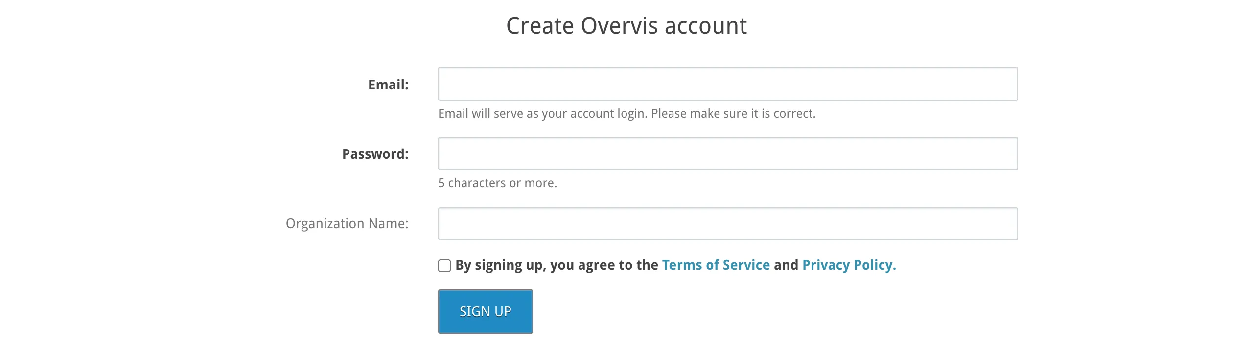
On the registration page, fill in:
- Email — will be used for login and notifications. Double-check it before submitting.
- Password — minimum 5 characters.
- Organization name — optional. If left blank, a default name is derived from your email address. You can change it later.
- Terms checkbox — you must agree to the Terms of Service and Privacy Policy to continue.
Click Sign up.
After registration, you are automatically logged in and redirected to the Create Network page (covered in the next step). A confirmation email is sent to the address you provided — click the link in it within 24 hours to keep your account active.
During registration, Overvis creates an organization for your account. In Overvis, an organization is the unit of billing and access control — it groups networks, users, and permissions together. It does not have to correspond to a real-world company: a single company might use several Overvis organizations to separate different sites, projects, or cost centers. For details on managing organizations and inviting team members, see Organizations & Users.
Step 3: Register the Controller in Overvis
Section titled “Step 3: Register the Controller in Overvis”In Overvis, a network represents a communication controller and all the Modbus RTU devices accessible through it. The next step is to create a network — tell Overvis how to find and access your controller.
Navigate to the Create Network page — if you just registered, you are already there.
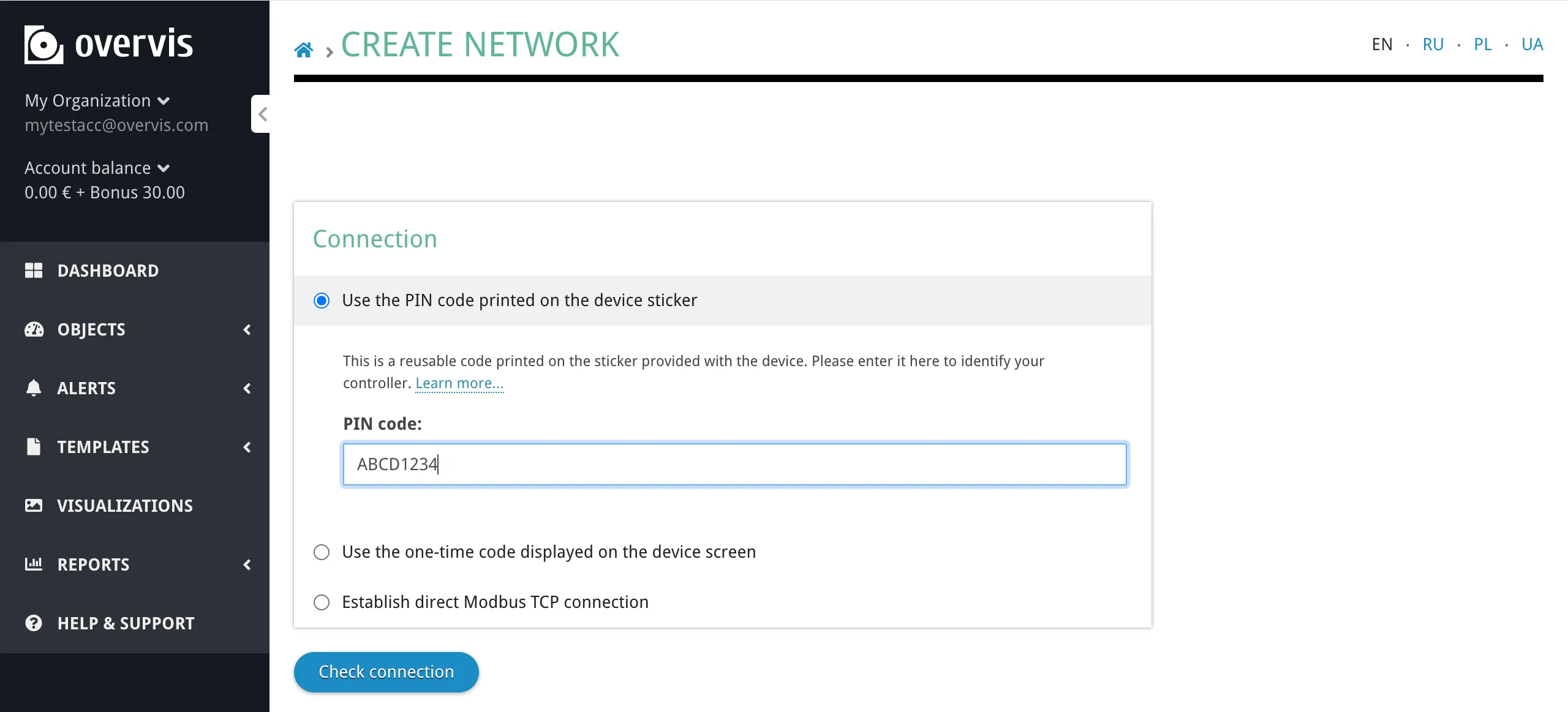
Find the PIN code
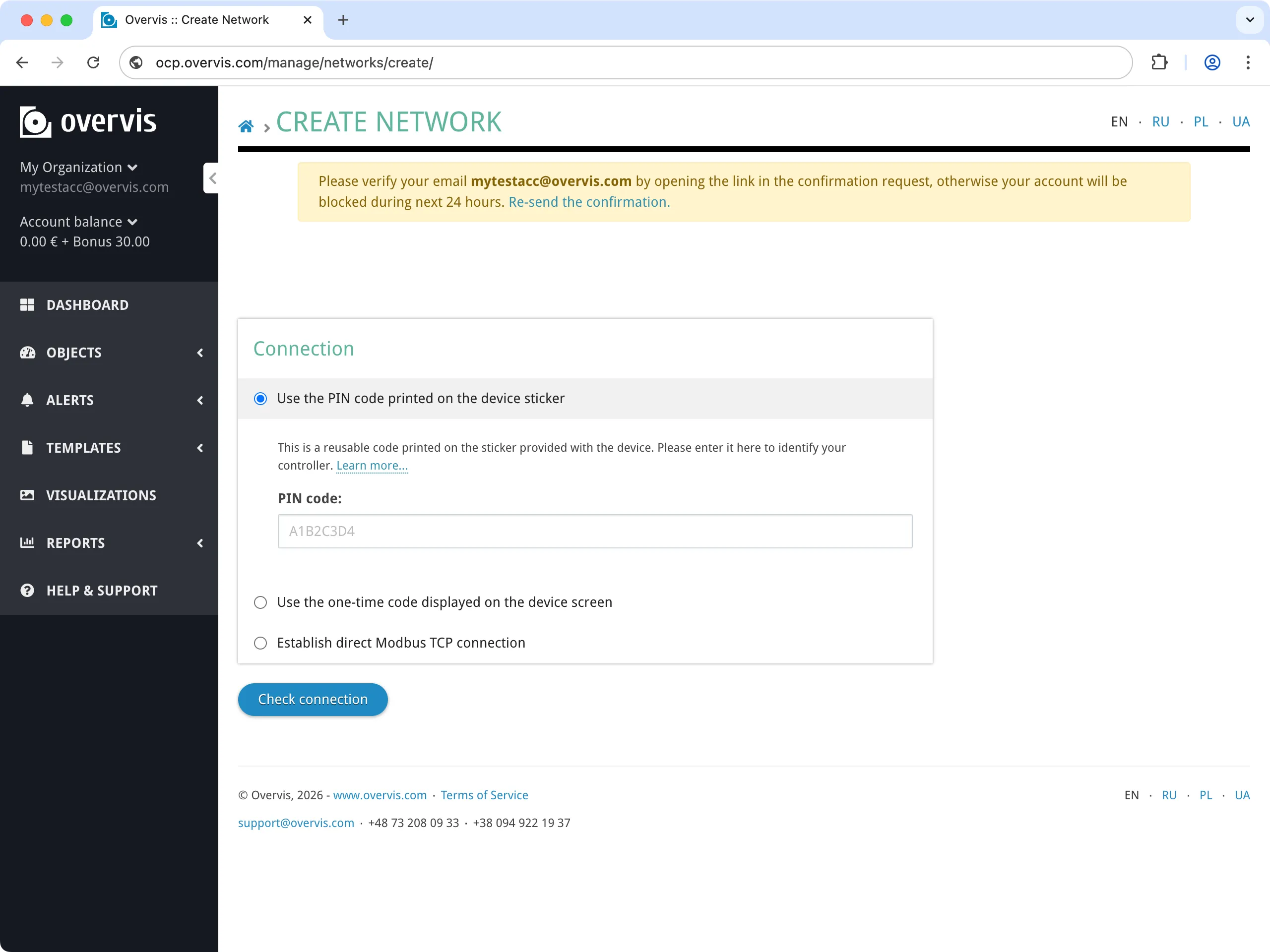
Section titled “Find the PIN code”Locate the sticker on your MC252 (or other Overvis-compatible controller). It contains a QR code and a PIN — an 8-character alphanumeric code (e.g. A1B2C3D4).

Create the network
Section titled “Create the network”Enter the PIN from the device label into the PIN code field and click Check connection to verify the controller is online and reachable.
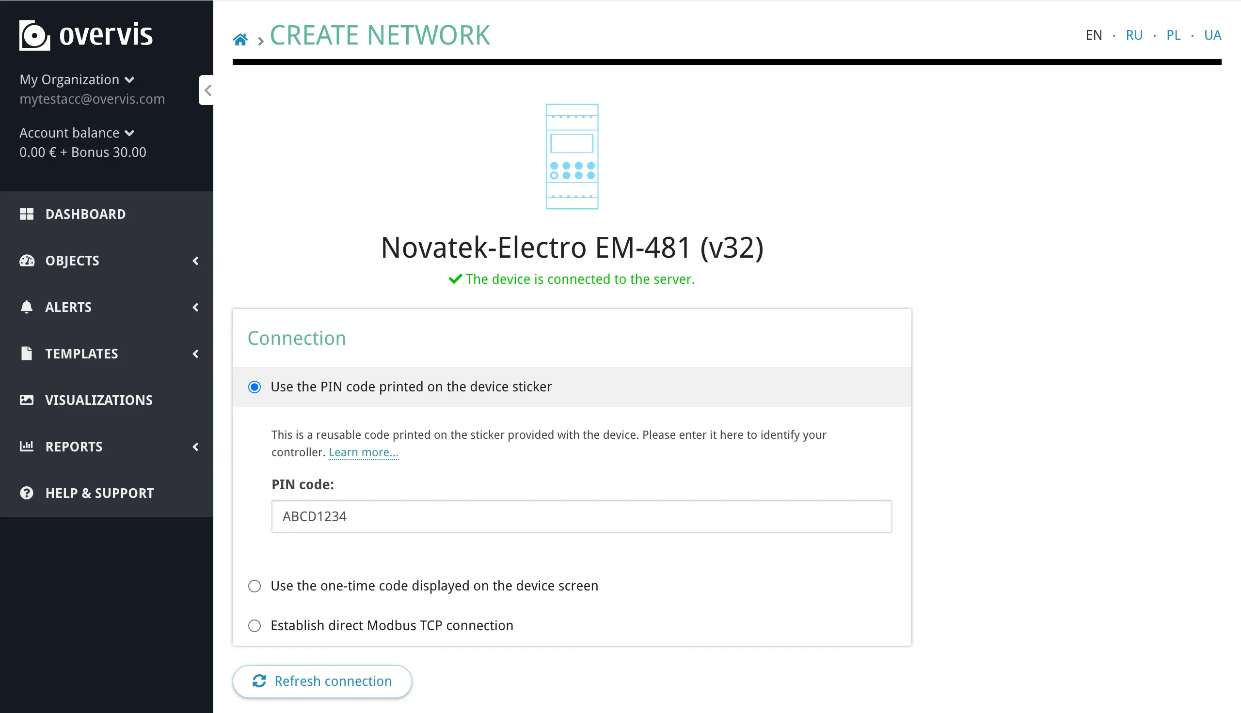
If the check succeeds, Overvis confirms the connection and shows the controller details. If it fails, make sure the controller is powered on, connected to the internet (see Step 1), and try again.
Give your network a descriptive name (e.g. “Warehouse”, “Office HVAC”, “Home Heating”) and click Create network to finalize.
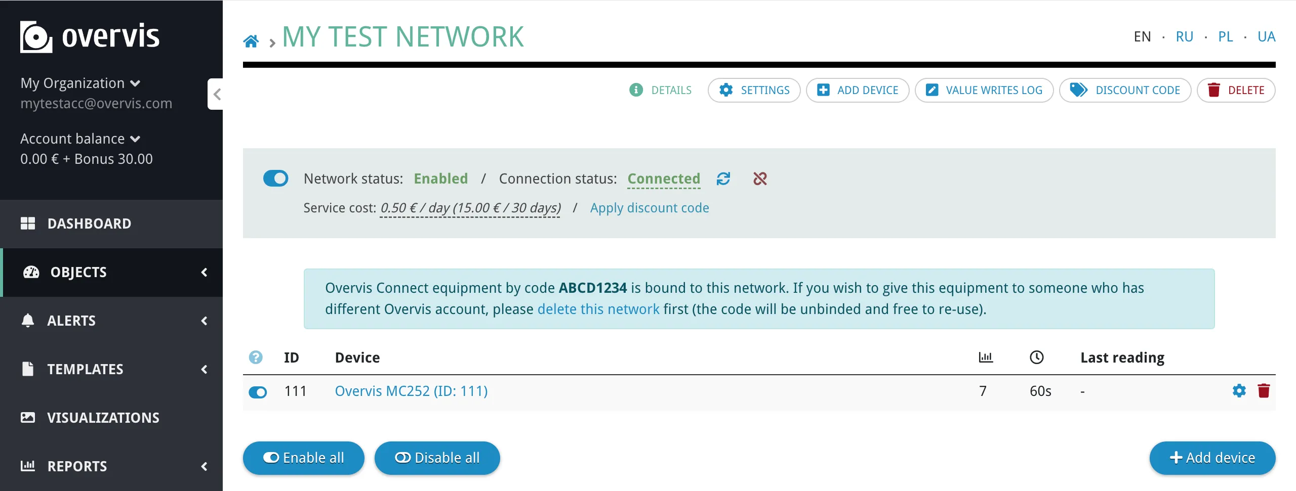
After creation, you are taken to the network page where you can see the controller and its connection status. Verify that the status shows the controller as connected before proceeding to the next step.
Step 4: Connect a Modbus RTU Device via RS-485
Section titled “Step 4: Connect a Modbus RTU Device via RS-485”With the controller registered in Overvis, it is time to connect an actual Modbus RTU device to it. This step has two parts: physical wiring via RS-485 and registering the device in Overvis.
Wire the RS-485 connection
Section titled “Wire the RS-485 connection”Connect the Modbus RTU device to the communication controller using a twisted-pair cable:
- Controller terminal A (non-inverted, D+) → Device terminal A (D+, +)
- Controller terminal B (inverted, D−) → Device terminal B (D−, −)
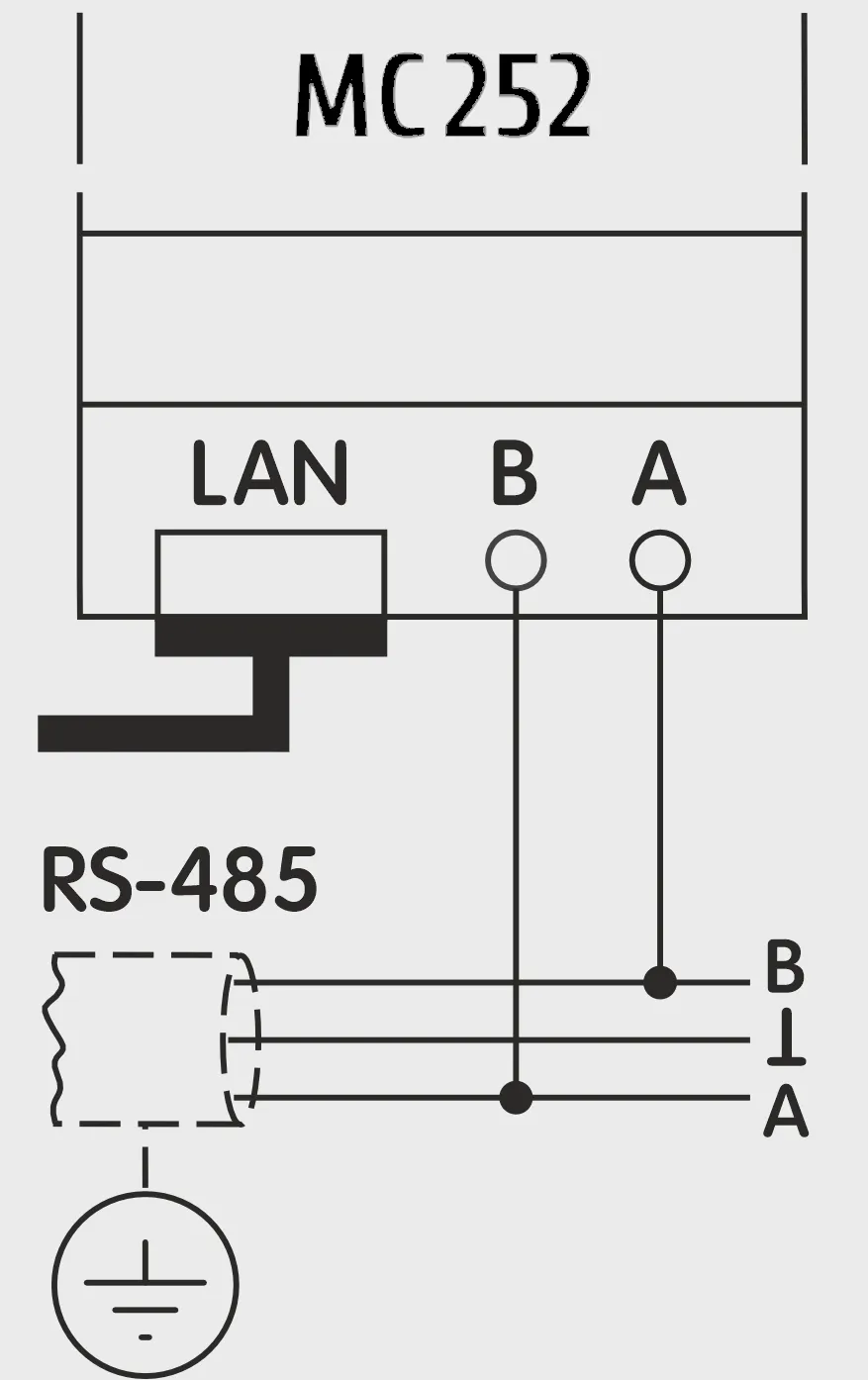
Make sure both devices use the same serial communication settings (baud rate, parity, stop bits). The MC252 defaults to 9600 baud, Modbus RTU, with automatic stop bit detection. Consult your device’s documentation and adjust settings on the controller if needed (via the MC252 web interface, Modbus tab — see MC252 Quick Start).
Add the device in Overvis
Section titled “Add the device in Overvis”- Open your network page in Overvis.
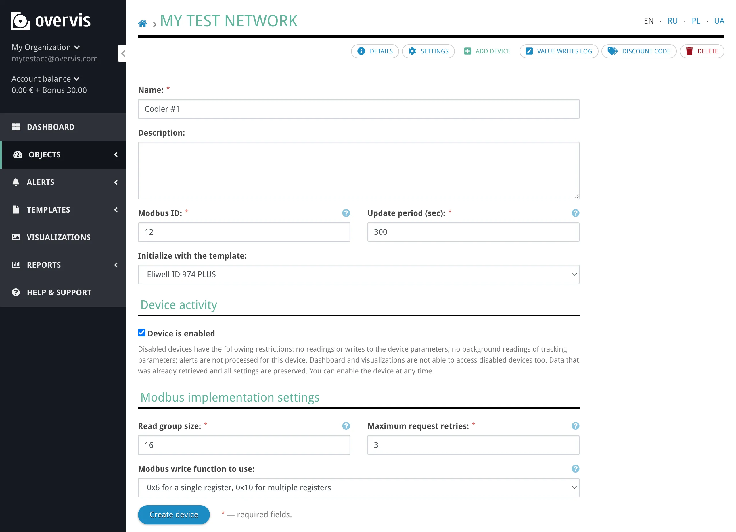
- Click Add Device in the sidebar navigation.
- Fill in the device Name and Modbus ID (unit ID, 0–255 — check your device’s documentation or DIP switches).
- In the Initialize with the template dropdown, select a template that matches your device model. Templates pre-configure all parameters (register addresses, data types, names, units) so you don’t have to set them up manually. Overvis includes templates for many common industrial devices.
- Click Create device.
If no template is available for your device, you can add parameters manually after creating the device — see Step 5 and the Networks, Devices & Parameters documentation. You can also create your own templates for reuse — see Device Templates.
Step 5: Read Device Data
Section titled “Step 5: Read Device Data”Once a device is added to your network, you can view its data in Overvis.
- From the network page, click on the device name to open the device page.
- The Details page shows the time of the last read at the top, followed by a list of parameters. Parameters are grouped into sections: Tracked (values are stored historically), Programmed (writable settings), and Untracked (read but not stored). If you applied a device template, all parameters are pre-configured with names, data types, and these flags.
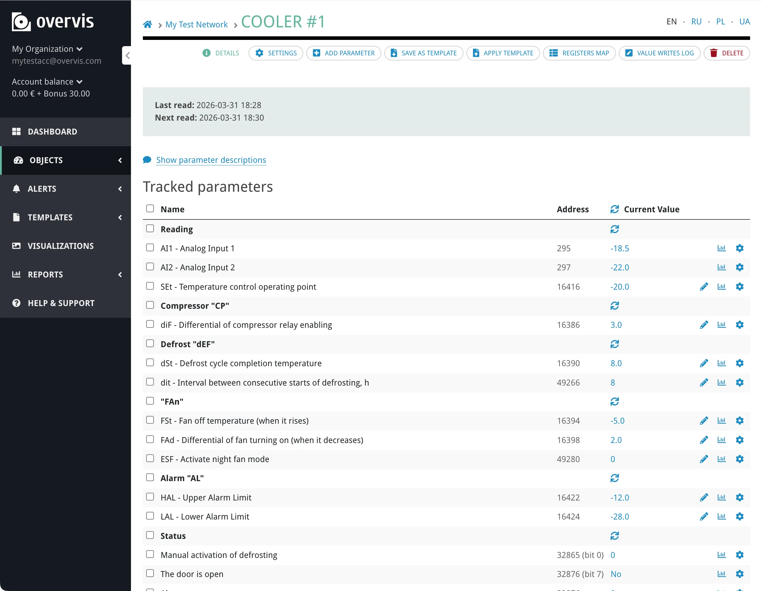
Each parameter row shows the parameter name, its Modbus address, and the current value (with units). Click on a value to refresh it from the device on demand.
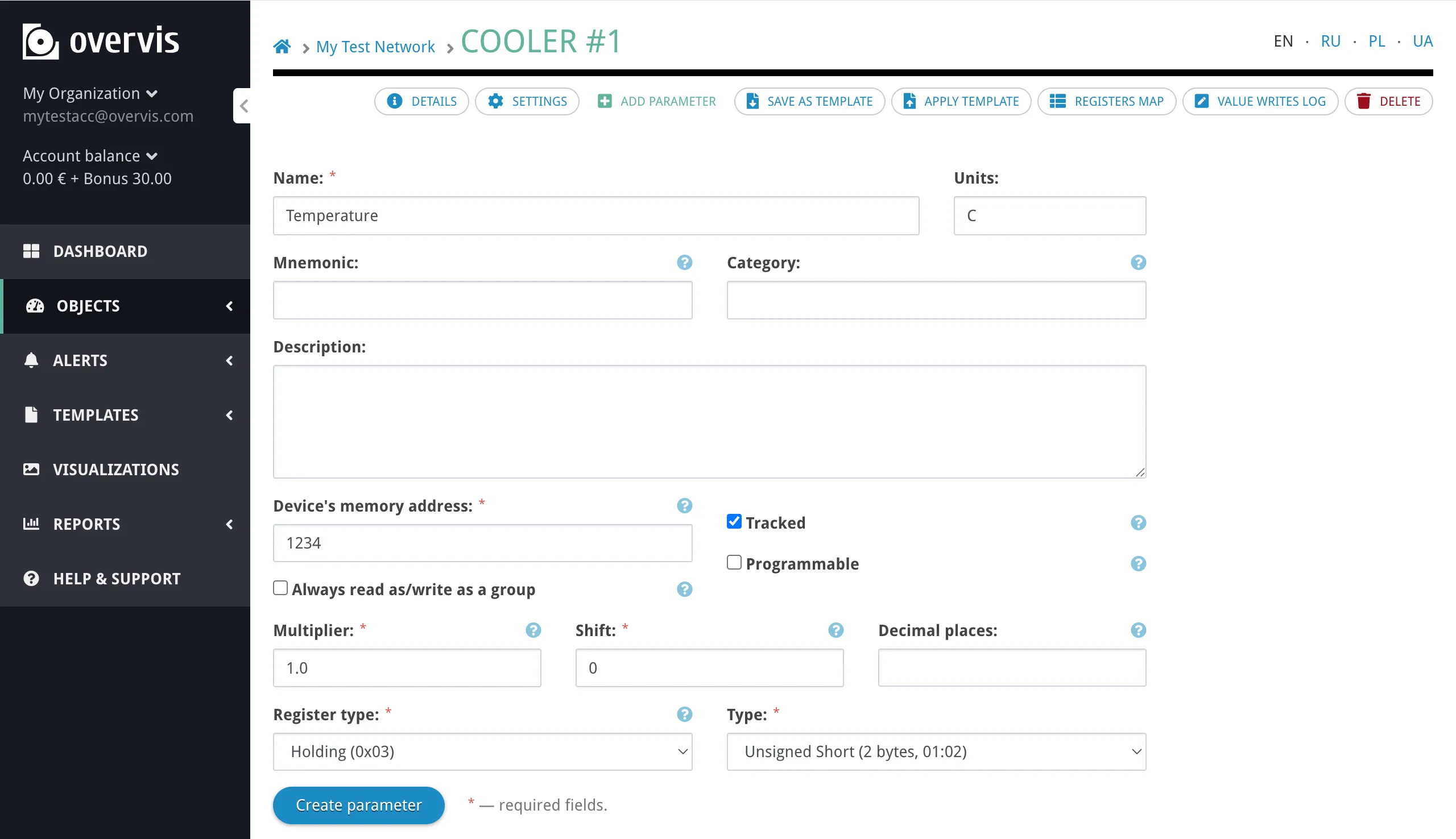
If you did not use a template, or need to add additional parameters, click Add Parameter in the sidebar and specify:
- Name — a human-readable label for the parameter.
- Device’s memory address — the Modbus register number (from your device’s documentation).
- Register type — Holding Register, Input Register, Coil, or Discrete Input.
- Type — how to interpret the register value (Int16, Uint16, Int32, Float32, etc.).
- Units — measurement units for display (°C, kWh, V, A, etc.).
Click Create parameter to save.
Step 6: Write a Value to a Device
Section titled “Step 6: Write a Value to a Device”Overvis allows you to write values to Modbus registers on the device — for example, changing a temperature setpoint, switching an output on or off, or adjusting a configuration parameter.
Parameters in the Programmed section (those with the Programmable flag — set by the template or manually when adding a parameter) have a pencil icon next to their value. To change a value:
- Click the pencil icon next to the parameter you want to change.
- An inline editor appears in the row — enter the new value (or select from a dropdown for enumerated parameters).
- Confirm the write.
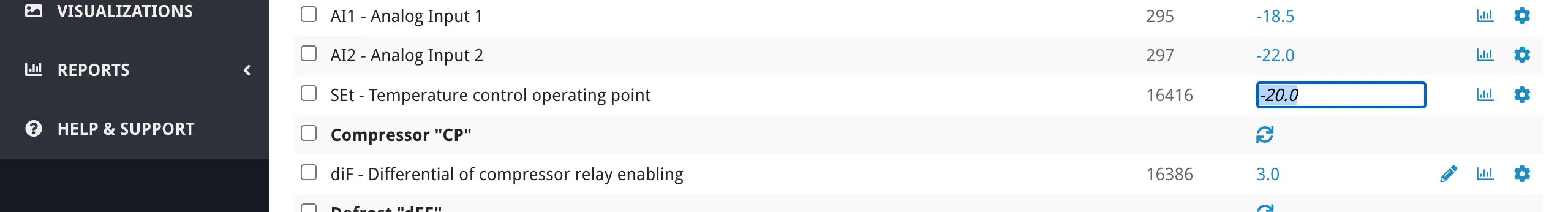
Overvis sends the Modbus write command to the device through the controller. The displayed value updates on the next read cycle (by default every 10 minutes, configurable per device in its settings).
What’s Next?
Section titled “What’s Next?”You now have a working Overvis Cloud setup with live data from your equipment. Here are the features to explore next:
- Alerts — configure automated notifications (email, SMS, voice call) when parameter values exceed thresholds or devices go offline.
- Visualizations — build custom interactive dashboards with charts, gauges, and controls.
- Device Templates — use pre-configured parameter sets for quick device setup, or create your own.
- Parameter Values Report — generate and export historical data reports.
- HACCP Reports — temperature monitoring reports for food safety compliance.
- Organizations & Users — invite team members and manage access permissions.
Free trial bonus
Section titled “Free trial bonus”Every new account receives a €30 bonus — enough for 1–2 months of free experimentation, depending on the number of connected networks. No payment is required to get started. For pricing details and payment options, see Billing.
Getting Help
Section titled “Getting Help”If you run into problems during setup:
- Connection issues (device not connecting, timeout errors, no data) — see Connecting Equipment for troubleshooting and alternative connection methods.
- Platform questions (navigation, features, configuration) — see the relevant section of the Overvis Cloud documentation.
- MC252-specific issues — see the MC252 Quick Start Guide and MC252 Troubleshooting.
For direct assistance:
- Email: support@overvis.com
- Support portal: www.overvis.com/support