

OB-216 Operating Manual
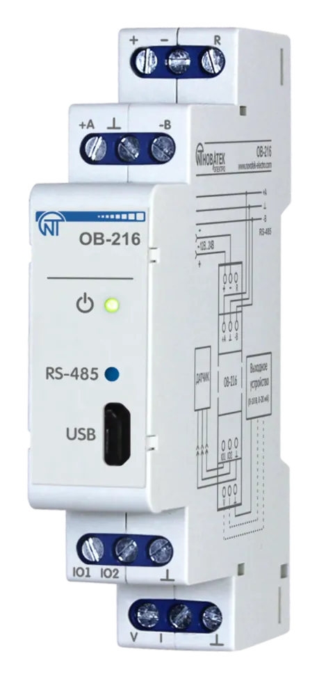
NOVATEK-ELECTRO LTD
Intelligent industrial electronic
DIGITAL INPUT/OUTPUT MODULE OB-216
OPERATING MANUAL
Quality control system on the development and production complies with requirements ISO 9001:2015
Dear customer,
Company NOVATEK-ELECTRO LTD. thanks you for purchasing our devices.
You will be able to use properly the device after carefully studying the Operating Manual.
Keep the Operating Manual throughout the service life of the device.
UKRAINE, Odesa — www.novatek-electro.com
1 Purpose
Section titled “1 Purpose”Digital input/output module OB-216 (hereinafter referred to as the Device or OB-216) can be used as:
- remote DC voltage meter (0 – 10 V);
- remote meter of direct current (0 – 20 mA);
- remote temperature meter when connecting an analog sensor NTC (10KB), PTC 1000 or PT 1000;
- remote temperature or humidity meter when connecting a digital sensor DS18B20, DHT21, DHT22 or AM2301;
- counter of impulses with saving the result in memory.
OB-216 provides:
- monitoring the state (closed / open) of the contact at the input of the «dry contact» type;
- issue of an analog signal (0 - 10 V, 0 - 20 mA) at the analog output.
RS-485 or USB interfaces provide control over the Modbus protocol of devices connected to the analog output (Figure 1, pos. 9, 10), reading sensor readings, setting device parameters. The control is carried out using the program “Control Panel OB-215/OB-216” or other software supporting the MODBUS protocol.
Power supply of the device and data exchange are indicated by indicators on the front panel (Figure 1, pos. 2, 3).
The overall and mounting dimensions and controls of OB-216 are shown in Figure 1.
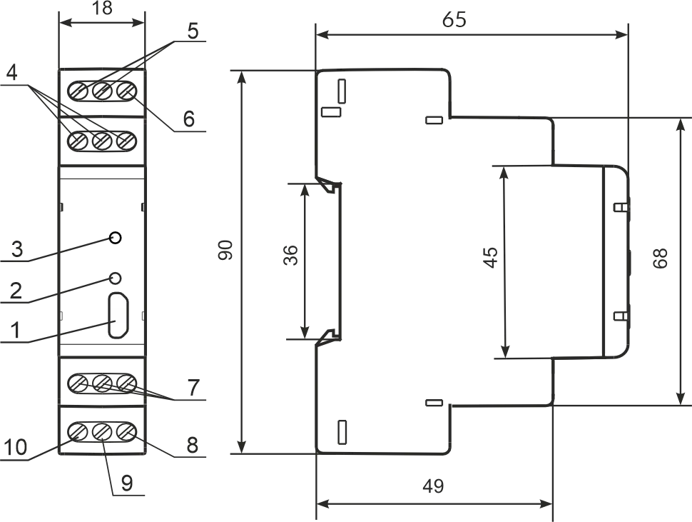
1 – microUSB connector;
2 – data exchange indicator;
3 – power supply indicator;
4 – terminals for RS-485 connection;
5 – terminals for power supply;
6 – terminal for restarting the device;
7 – terminals for connecting sensors;
8 – terminal “ground” of the analog output;
9 – current terminal 0 - 20 mA analog output;
10 – voltage terminal 0 - 10 V analog output.
Figure 1 – OB-216 front panel and overall dimensions
2 Terms and Abbreviations
Section titled “2 Terms and Abbreviations”- Modbus – standard, packet communication protocol based on “client-server” technology for industrial electronic devices;
- Modbus RTU – device communication protocol, through which the packet is transmitted byte by byte;
- Modbus ASCII – device communication protocol through which a packet is transmitted in the form of ASCII characters;
- RS-485/EIA-485 – network standard for communication of devices via twisted pair;
- Twisted pair – a pair of insulated conductors in a cable, twisted together to reduce distortion of transmitted signals;
- W/R – write/read;
- Indicator – a single LED indicator;
- R – reading.
3 Complete Set
Section titled “3 Complete Set”| Item | Quantity |
|---|---|
| OB-216 | 1 pcs. |
| PC connection cable (microUSB) | 1 pcs. |
| Operating manual | 1 pcs. |
| Packaging | 1 pcs. |
4 Technical Specifications
Section titled “4 Technical Specifications”Main Technical Characteristics
Section titled “Main Technical Characteristics”| Parameter | Value |
|---|---|
| DC supply voltage | 10 – 30 V |
| Number of connected sensors | 1 |
| DC voltage measurement error in the range 0 - 10 V | ≤ 1% |
| DC current measurement error in the range of 0 - 20 mA | ≤ 1% |
| Temperature measuring range (NTC 10KB) | –25…+125 °C |
| Temperature measuring range (PTC 1000) | –50…+120 °C |
| Temperature measuring range (PT 1000) | –50…+250 °C |
| Maximum pulse frequency in the «Pulse counter/Logic input» mode | 200 Hz |
| Maximum pulse frequency in the «Voltage/current pulse counter» mode | 10 Hz |
| Maximum voltage supplied to the input «IO1», «IO2» | no more supply voltage |
| Number of outputs | 1 |
| Output voltage range | 0 – 10 V |
| Output voltage error | 0.5 % |
| Output current range | 0 – 20 mA |
| Output current error | 0.5% |
| Ready time | ≤ 2 s |
| Maximum power consumption | ≤ 1 W |
| Communication interfaces | RS (EIA/TIA)–485, USB |
| Data exchange protocol Modbus | MODBUS RTU / ASCII |
| Nominal operating mode | long lasting |
| Weight | ≤ 0.07 kg |
| Overall dimensions, H×W×L | 90×65×18 mm |
| Cross-section of conductors for connection | 0.5 – 3.0 mm² |
| Screw tightening torque | 0.4 N·m |
| Device protection degree | IP20 |
| Electric shock protection class | III |
| Climatic performance | NF 3.1 |
| Permissible degree of pollution | II |
- The device maintains its performance at any position in space
- Installation (mounting) – DIN rail 35 mm
- Body material – self-extinguishing plastic
- The device meets the requirements of the following: EN 60947-1; EN 60947-6-2; EN 55011; EN 61000-4-2
- Harmful substances in amounts exceeding maximum permissible concentrations are not available
Temperature Measurement Error When Using Analog Sensors
Section titled “Temperature Measurement Error When Using Analog Sensors”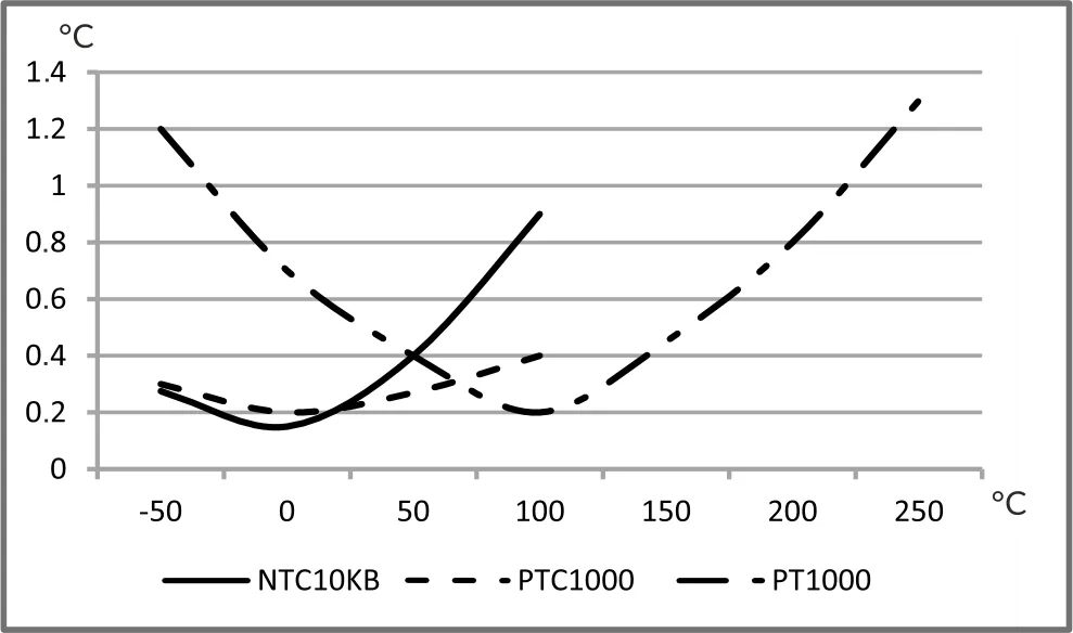
5 Operation Conditions
Section titled “5 Operation Conditions”The device is intended for operation in the following conditions:
- Ambient temperature: from minus 35 to +45 °С
- Atmospheric pressure: from 84 to 106.7 kPa
- Relative humidity (at temperature of +25 °С): 30 … 80 %
If the temperature of the device after transportation or storage differs from the ambient temperature at which it is supposed to be operated, then before connecting to the mains keep the device under the operating conditions within two hours (because of condensation may be on the product elements).
6 Connecting Device
Section titled “6 Connecting Device”An error during installation work can damage the unit and appliances connected to it.
For reliable contact, it is necessary to tighten the terminal block screws with force of 0.4 N·m.
When the tightening torque is reduced, the junction may heat up, the terminal block may melt and the wire may catch fire. With an increase in the tightening torque, it is possible that the threads of the terminal block screws are broken or the wire to be connected is pinched.
Analog Measurement Mode Wiring Diagram
Section titled “Analog Measurement Mode Wiring Diagram”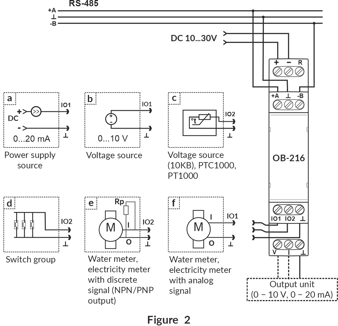
Figure 2 – Analog measurement mode wiring diagram
Wiring Diagram for Operation with Digital Sensors
Section titled “Wiring Diagram for Operation with Digital Sensors”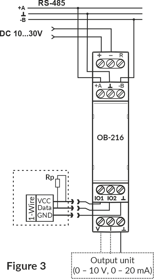
Figure 3 – Wiring diagram for operation with digital sensors
1. Connect the device in accordance with Figure 2 (when using the device in the mode of measuring analog and discrete signals) or in accordance with Figure 3 (when using the device with digital sensors) and check the correct connection. To connect the device to the Modbus network, use a twisted pair cable of Cat.1 category or higher.
2. Check the correct connection according to Connecting Different Types of Sensors and the diagrams in Figure 2 or Figure 3.
Connecting Different Types of Sensors
Section titled “Connecting Different Types of Sensors”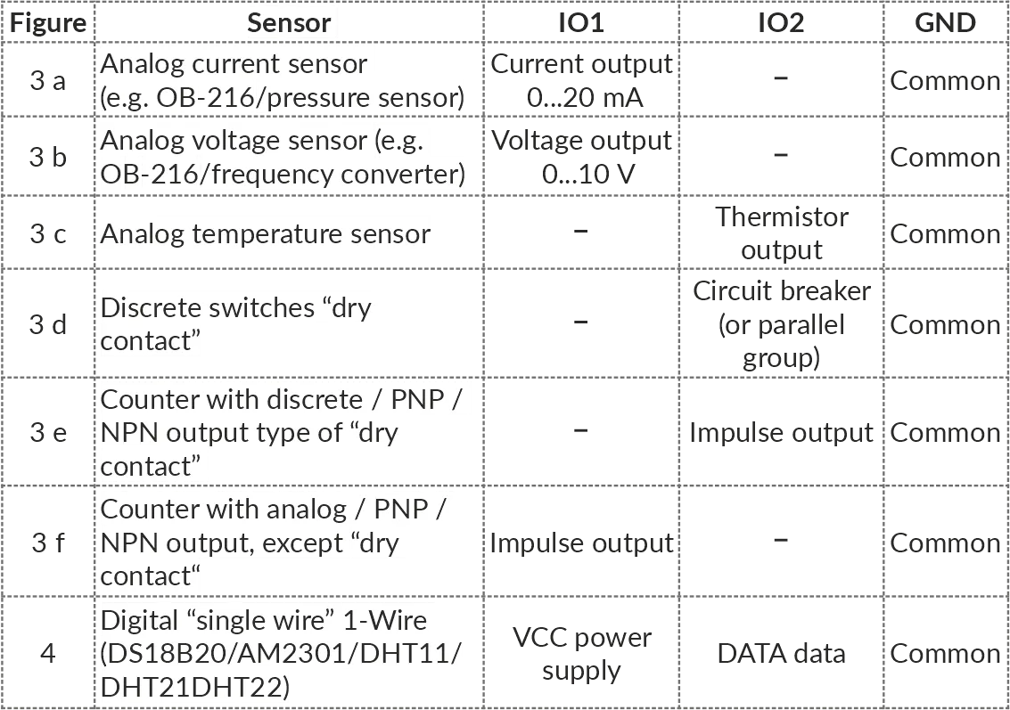
7 Use of Device
Section titled “7 Use of Device”After power is applied, the indicator « ⏻ » flashes for 1.5 s, then the indicators « ⏻ » and «RS-485» (Figure 1, pos. 2, 3). After 0.5 s, the «RS-485» indicator goes out. During data exchange, the «RS-485» flashes, otherwise the indicator does not light up.
To configure the device, use the program «Control Panel OB-215/OB-216» (available at website www.novatek-electro.com in the «Software» section) or other software compatible with the Modbus RTU/ASCII. The program connects to the device via USB or RS-485 interface.
8 Device Operation
Section titled “8 Device Operation”Pulse Counter (Discrete Signal)
Section titled “Pulse Counter (Discrete Signal)”Connect an external device according to Figure 2 (e).
Configure the device for operation in the pulse counter mode for counting discrete signals (OB-216 Settings, address 100, value 0).
Select the pulse detection algorithm in the Pulse counter mode register (address 106).
In this mode, the device counts the number of pulses at the «IO2» (input with a duration not less than the value specified in the OB-216 Settings, address 107, the value is specified in ms). The data is saved into memory with a frequency of 1 minute. If the device was switched off before 1 minute has elapsed, the last stored value will be restored when switched on.
Upon reaching the value indicated in the register (address 108), the counter is incremented by one (Additional Registers, address 4:5).
To configure the initial value of the pulse counter, write the required value into the register (Additional Registers, address 4:5). Then the counter will count pulses from the entered value.
When changing the value in the register (address 108), all stored pulse counter values will be deleted.
Impulse Counter (By Voltage)
Section titled “Impulse Counter (By Voltage)”Connect an external device according to Figure 2 (f).
Configure OB-216 to operate in the pulse counter mode for counting voltage pulses (OB-216 Settings, address 100, value 11). Select the pulse detection algorithm in the Pulse counter mode register (address 106).
Set the thresholds registers (addresses 104, 105) to specify the upper and lower voltage thresholds at which the pulse will be counted.
In this mode, the device counts the number of voltage pulses in accordance with the set thresholds. If the voltage value changes within the upper and lower thresholds, the device will not register these pulses. The number of impulses is saved to memory every minute. If the device was switched off before 1 minute has elapsed, the last stored value will be restored when switched on.
Upon reaching the value indicated in the register (address 108), the counter is incremented by one (Additional Registers, address 4:5).
To configure the initial value of the pulse counter, write the required value into the register (Additional Registers, address 4:5). Then the counter will add pulses to the initial value.
When changing the value in the register (address 108), all stored pulse counter values will be deleted.
Impulse Counter (By Current)
Section titled “Impulse Counter (By Current)”Connect an external device according to Figure 2 (f).
Configure OB-216 to operate in the impulse counter mode for counting current impulses (OB-216 Settings, address 100, value 12).
Select the pulse detection algorithm in the Pulse counter mode register (address 106).
Set the thresholds registers (addresses 104, 105) to specify the upper and lower current thresholds at which the impulse will be recorded.
In this mode, the device counts the number of current impulses in accordance with the set thresholds. If the current value changes within the upper and lower thresholds, the device will not register these impulses. The number of impulses is saved to memory every minute. If the device was switched off before 1 minute has elapsed, the last stored value will be restored when switched on.
Upon reaching the value indicated in the register (address 108), the counter is incremented by one (Additional Registers, address 4:5).
To configure the initial value of the impulse counter, write the required value into the register (Additional Registers, address 4:5). Then the counter will add pulses to the initial value.
When changing the value in the register (address 108), all stored impulse counter values will be deleted.
Logic Input
Section titled “Logic Input”Connect the device according to Figure 2 (d). Configure it for operation in the «Logic input» (OB-216 Settings, address 100, value 1).
When the logical state at the «IO2» terminal (Figure 1, pos. 7) changes to a low level, the device will set bit 18 (Additional Registers, address 2:3) equal to 1.
When the logical state at the «IO2» terminal (Figure 1, pos. 7) changes to a high level, the device will reset bit 18 (Additional Registers, address 2:3) equal to 0.
Voltage Measurement
Section titled “Voltage Measurement”Connect the device according to Figure 2 (b).
Configure it to operate in the «Voltage measurement» (OB-216 Settings, address 100, value 2).
The Measured value register (Additional Registers, address 6) will display the voltage measured at the «IO1» (Figure 1, pos. 7).
If the device has to indicate overvoltage (or undervoltage), the corresponding thresholds should be set (OB-216 Settings, addresses 104, 105). Write the upper threshold value to register 104 and lower threshold value to register 105. When the voltage value exceeds the threshold, the corresponding bit will be set to «1» (bit 20 – voltage value above the upper threshold, bit 21 – voltage value below the lower threshold) (see Additional Registers, address 2:3).
Voltage Measurement with Value Conversion
Section titled “Voltage Measurement with Value Conversion”To convert the measured voltage to another value, turn on the conversion (OB-216 Settings, address 130, value 1) and set the conversion ranges (addresses 131 – 134).
For example, the measured voltage needs to be converted to pressure bars with the following sensor parameters:
- a voltage of 0.5 V corresponds to a pressure of 1 bar;
- a voltage of 8 V corresponds to a pressure of 25 bar.
Configure the conversion ranges as follows:
- minimum input value (address 131, value
50which corresponds to 0.5 V), - maximum input value (address 132, value
800corresponds to 8 V), - minimum converted value (address 133, value
1corresponds to 1 bar), - maximum converted value (address 134, value
25corresponds to 25 bar).
The converted value will be output to a Converted value register (Additional Registers, address 16).
Voltage Measurement with Analog Voltage Output
Section titled “Voltage Measurement with Analog Voltage Output”To output the measured voltage to the analog voltage output, select the analog voltage output (OB-216 Settings, address 150, value 1). Check the load connection for the voltage output (Figure 1, pos. 10). Set the conversion ranges (OB-216 Settings, registers 153-156).
For example, to convert a measured voltage in the 1 V to 10 V range to a voltage in range of 0 V to 5 V:
- write the minimum input voltage value into the register with address 153 (
100corresponding to 1 V); - write the maximum input voltage value into the register with address 154 (
1000corresponding to 10 V); - write the minimum output voltage value into the register with address 155 (
0); - write the maximum output voltage value into the register with address 156 (
500corresponding to 5 V).
The converted analog value will be output to a Converted analog value register (Additional Registers, address 17).
Voltage Measurement with Analog Current Output
Section titled “Voltage Measurement with Analog Current Output”To output the measured voltage to the analog current output, select the analog current output (OB-216 Settings, address 150, value 2). Check the load connection for the current output (Figure 1, pos. 9). Set the conversion ranges (OB-216 Settings, registers 153-156).
For example, to convert a measured voltage in the 1 V to 10 V range to a current (4 mA to 20 mA range):
- write the minimum input voltage value into the register with address 153 (
100corresponding to 1 V); - write the maximum input voltage value into the register with address 154 (
1000corresponding to 10 V); - write the minimum output current value into the register with address 155 (
400corresponding to 4 mA); - write the maximum output current value into the register with address 156 (
2000corresponding to 20 mA).
The converted analog value will be output to a Converted analog value register (Additional Registers, address 17).
Output Voltage to Analog Output in Manual Mode
Section titled “Output Voltage to Analog Output in Manual Mode”To output voltage to the analog output in manual mode, select the analog voltage output (OB-216 Settings, address 150, value 3). Check the load connection for the voltage output (Figure 1, pos. 10). Afterwards use the register for writing value in manual mode (address 151) to control the output.
For example, when the value 500, is written to the register, a 5 V level voltage will appear at the analog voltage output (Figure 1, pos. 10) (when the conversion of the output value is disabled).
To convert a manually set value, turn on the conversion of the output value by writing the value «1» to the register (address 152), and the required ranges in the corresponding registers (addresses 153-156).
Current Measurement
Section titled “Current Measurement”Connect the device according to Figure 2 (a).
Configure it to operate in the «Current measurement» (OB-216 Settings, address 100, value 3).
The Measured value register (Additional Registers, address 6) will display the current measured at the «IO1» terminal (Figure 1, pos. 7).
If the device has to indicate overcurrent (or undercurrent), the corresponding thresholds should be set (OB-216 Settings, addresses 104, 105). Write the upper threshold value to register 104 and lower threshold value to register 105. When the current value is out of range, the corresponding bit will be set to «1» (bit 22 – current value above the upper threshold, bit 23 – current value below the lower threshold) (see Status Register, address 2:3).
Current Measurement with Value Conversion
Section titled “Current Measurement with Value Conversion”To convert the measured current to another value, turn on the conversion (OB-216 Settings, address 130, value 1) and set the conversion ranges (addresses 131 – 134).
For example, the measured current needs to be converted to pressure bars with the following sensor parameters:
- a current of 4.5 mA corresponds to a pressure of 1 bar;
- a current of 20 mA corresponds to a pressure of 25 bar.
Configure the conversion ranges as follows:
- minimum input value (address 131, value
450which corresponds to 4.5 mA), - maximum input value (address 132, value
2000corresponds to 20 mA), - minimum converted value (address 133, value
1corresponds to 1 bar), - maximum converted value (address 134, value
25corresponds to 25 bar).
The converted value will be output to a Converted value register (Additional Registers, address 16).
Current Measurement with Analog Voltage Output
Section titled “Current Measurement with Analog Voltage Output”To output the measured current to the analog voltage output, select the analog voltage output (OB-216 Settings, address 150, value 1). Check the load connection for the voltage output (Figure 1, pos. 10). Set the conversion ranges (OB-216 Settings, registers 153-156).
For example, to convert a measured current in the 0 mA to 20 mA range to a voltage (0 V to 5 V range):
- write the minimum input current value into the register with address 153 (
0); - write the maximum input current value into the register with address 154 (
2000corresponding to 20 mA); - write the minimum output voltage value into the register with address 155 (
0); - write the maximum output voltage value into the register with address 156 (
500corresponding to 5 V).
The converted analog value will be output to a Converted analog value register (Additional Registers, address 17).
Current Measurement with Output to Analog Current Output
Section titled “Current Measurement with Output to Analog Current Output”To output the measured current to the analog current output, select the analog current output (OB-216 Settings, address 150, value 2). Check the load connection for the current output (Figure 1, pos. 9). Set the conversion ranges (OB-216 Settings, registers 153-156).
For example, to convert a measured current in the 0 mA to 10 mA range to a current in range of 4 mA to 20 mA:
- write the minimum input current value into the register with address 153 (
0); - write the maximum input current value into the register with address 154 (
1000corresponding to 10 mA); - write the minimum output current value into the register with address 155 (
400corresponding to 4 mA); - write the maximum output current value into the register with address 156 (
2000corresponding to 20 mA).
The converted analog value will be output to a Converted analog value register (Additional Registers, address 17).
Current Output to Analog Output in Manual Mode
Section titled “Current Output to Analog Output in Manual Mode”To output current to the analog output in manual mode, select the analog current output (OB-216 Settings, address 150, value 4). Check the load connection for the current output (Figure 1, pos. 9). Afterwards use the register for writitng value in manual mode (address 151) to control the output.
For example, when the value 500, is written to the register, a 5 mA level current will appear at the analog current output (Figure 1, pos. 9) (when the conversion of the output value is disabled).
To convert a manually set value, turn on the conversion of the output value by writing the value «1» to the register (address 152), and the required ranges in the corresponding registers (addresses 153-156).
Temperature Measurement
Section titled “Temperature Measurement”In this mode, the device measures the temperature using an external analog thermistor.
Connect the device according to Figure 2 (c).
Configure it for operation in the «Temperature measurement» (OB-216 Settings, address 100, value 4, 5 or 6).
The Measured value register (Additional Registers, address 6) will display the temperature measured by thermistor connected to the «IO2» terminal (Figure 1, pos. 7).
Temperature values are displayed with an accuracy of tenths of a degree Celsius (1234 = 123.4 °С; 123 = 12.3 °С).
If the device has to indicate overheat (or underheat), the corresponding thresholds should be set (OB-216 Settings, addresses 104, 105). Write the upper threshold value to register 104 and lower threshold value to register 105. When the temperature value is out of range, the corresponding bit will be set to «1» (bit 24 – temperature above the upper threshold, bit 25 – temperature below the lower threshold) (see Status Register, address 2:3).
In order to correct the temperature measured by the sensor, enter the correction temperature into register 102 (OB-216 Settings), in tenths of a degree Celsius.
Temperature Measurement with Analogue Output
Section titled “Temperature Measurement with Analogue Output”To output the measured temperature to the analog output, write to the Analog output control register with address 150, the value «1» selects the analog voltage output (Figure 1, pos. 10), the value «2» selects the analog current output (Figure 1, pos. 9).
Set up the conversion range registers (addresses 153 – 156).
Connecting Digital Sensors
Section titled “Connecting Digital Sensors”The device supports digital sensors (one at a time) specified in the OB-216 Settings (address 101).
The measured values of the digital sensor can be read from the Temperature register with address 11 or Humidity register with address 12 (depending on which values the sensor measures), in Additional Registers.
Poll period of digital sensors is 3 seconds.
Temperature values are displayed with an accuracy of tenths of a degree Celsius (1234 = 123.4 °С; 123 = 12.3 °С).
Humidity values are displayed with an accuracy of tenths of a percent (800 = 80.0 %).
In order to correct the temperature measured by a digital sensor, enter the correction temperature into register 102 (OB-216 Settings), in tenths of a degree Celsius.
If the device has to indicate excess (or deficit) of the measured value, the working parameter and the corresponding thresholds should be set (OB-216 Settings, addresses 103, 104, and 105). Select the working parameter in the register 103. Write the upper threshold value to register 104 and lower threshold value to register 105. When the working parameter value exceeds the threshold, the corresponding bit will be set to «1» (bits 24 and 25 – temperature value above the upper or below the lower threshold, bits 26 and 27 – humidity value above the upper or below the lower threshold) (see Additional Registers, address 2:3).
Connection of Digital Sensors with Output to Analog Output
Section titled “Connection of Digital Sensors with Output to Analog Output”To output the working parameter of the digital sensor (OB-216 Settings, address 103) to the analog output, write to the Analog output control register with address 150, the value «1» selects the analog voltage output (Figure 1, pos. 10), the value «2» selects the analog current output (Figure 1, pos. 9).
Set up the conversion range registers (addresses 153 – 156).
9 Restarting the Device and Resetting to the Factory Settings
Section titled “9 Restarting the Device and Resetting to the Factory Settings”If you need to restart the device, close and hold contacts «R» and «–» for 3 seconds (Figure 1).
If it is required to restore the factory settings of the device, close and hold contacts «R» and «–» for more than 10 seconds (Figure 1). After 10 seconds, the device will restore factory settings and reboot.
Also, the above actions can be performed through the command register by writing the corresponding command into it (Command Registers, address 50).
10 Modbus Interface Reference
Section titled “10 Modbus Interface Reference”For USB and RS-485 interface configuration, supported functions, registers, message formats, and command details, see the dedicated OB-216 Modbus Interface Reference.
11 Safety Precautions
Section titled “11 Safety Precautions”It is not allowed water penetration on terminals and internal elements of the device.
During operation and maintenance, the regulatory document requirements must be met, namely:
- Regulations for Operation of Consumer Electrical Installations;
- Safety Rules for Operation of Consumer Electrical Installations;
- Occupational Safety in Operation of Electrical Installations.
12 Maintenance Procedure
Section titled “12 Maintenance Procedure”Recommended frequency of maintenance is every six months.
Maintenance Procedure:
- Check the connection reliability of the wires, if necessary, clamp with the force 0.4 N·m;
- Visually check the integrity of the housing;
- If necessary, wipe the front panel and the housing of the device with cloth.
Do not use abrasives and solvents for cleaning.
13 Transportation and Storage
Section titled “13 Transportation and Storage”The device in the original package is permitted to be transported and stored at the temperature from minus 45 to +60 °C and relative humidity of no more than 80 %, not in aggressive environment.
14 Service Life and Warranty
Section titled “14 Service Life and Warranty”The lifetime of the device is 10 years.
Shelf life is 3 years.
Warranty period of the device operation is 5 years from the date of sale.
During the warranty period of operation, the manufacturer performs free repair of the device, if the user has complied with the requirements of the Operating Manual.
Warranty service is performed at the place of purchase or by the manufacturer of the device. Post-warranty service of the device is performed by the manufacturer at current rates.
Before sending for repair, the device should be packed in the original or other packing excluding mechanical damage.
For all questions, please contact the manufacturer:
“Novatek-Electro” Ltd.
59, Mykhailo Boltenko (Admiral Lazarev) str., Odesa, Ukraine, 65007
Tel: +38 (067) 565 37 68 +38 (050) 359 39 11 +38 (063) 301 30 40
VN250731