User Web Interface
The Overvis MC252 features a built-in web interface for configuration, status monitoring, and management. You can access this interface using any standard web browser connected to the same network as the device.
Accessing the Interface
Section titled “Accessing the Interface”- Ensure the MC252 is powered on and connected to your network via Ethernet (uses standard HTTP port 80).
- Find the device’s IP address. You can display the current IP address on the MC252 screen by shortly pressing the R (Service) button.
- Enter this IP address into your web browser’s address bar (e.g.,
http://192.168.1.100).
Note: If your network uses a proxy server, you may need to add the MC252’s IP address to your browser’s exception list to access it locally.
Authentication
Section titled “Authentication”Upon accessing the device, you will be presented with a login page.
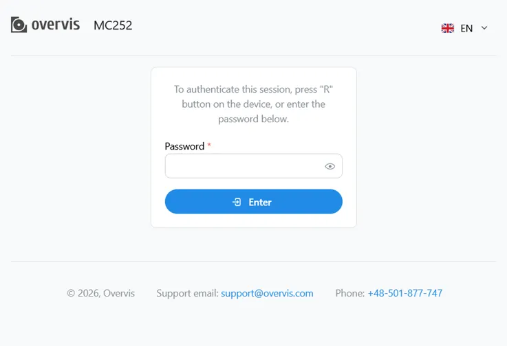 Fig. 1 - The login page
There are two ways to authorize access:
- Password: Enter the password printed on the device label.
- Physical Access: Shortly press the R (Service) button on the device to grant temporary access without a password (see Operating Manual).
Dashboard
Section titled “Dashboard”After logging in, the Dashboard provides a real-time overview of the device status.
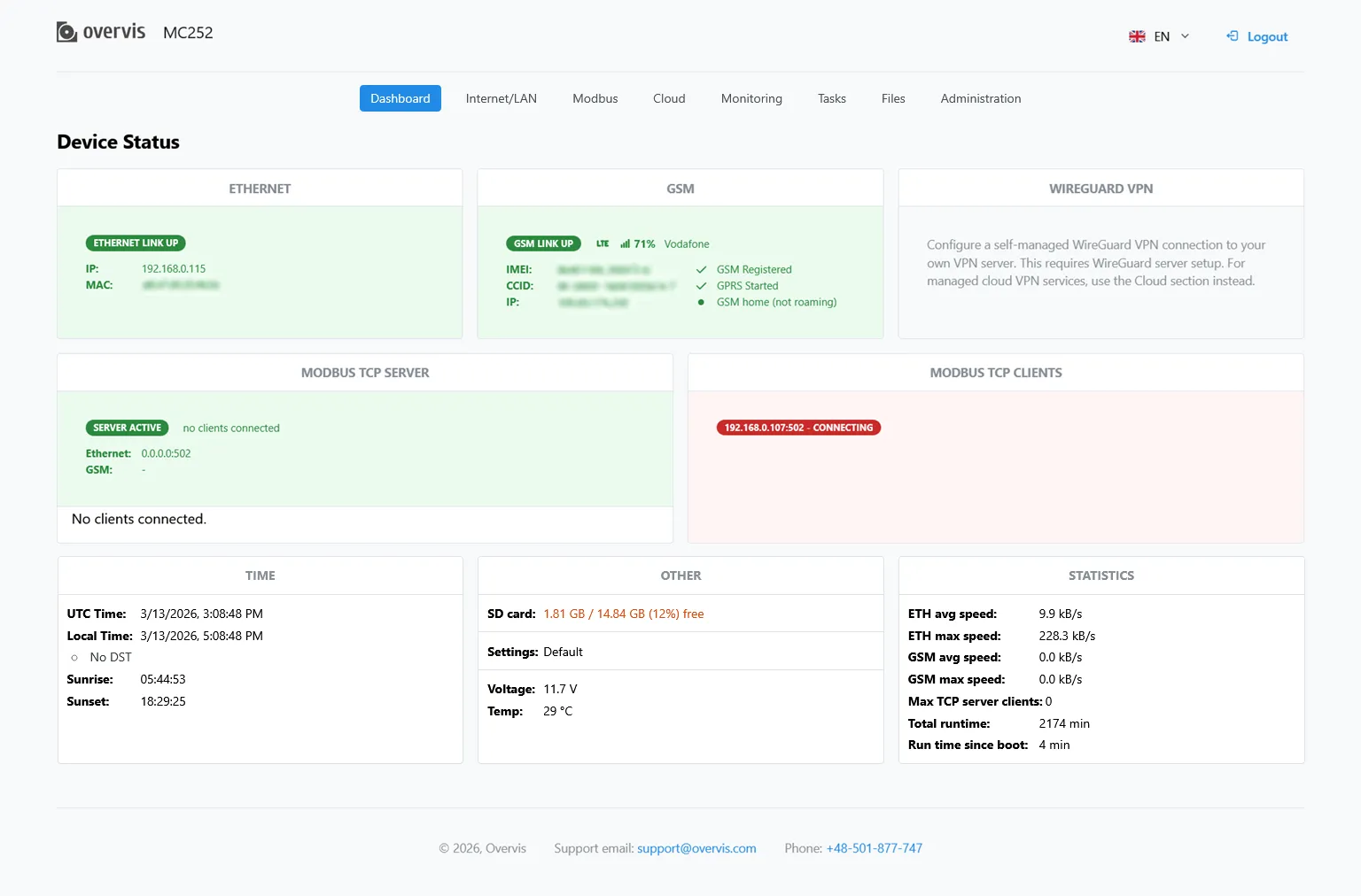 Fig. 2 - The dashboard page
The dashboard displays:
- TCP interface status
- Modbus connection states
- Memory card usage
- Data transfer statistics
- Current system time
Configuration
Section titled “Configuration”The web interface is divided into several tabs for different configuration aspects.
Tip: Most configuration pages include an “Open the documentation” link for detailed help on specific options. When you click Save & reset, settings are saved to memory and the device will restart to apply changes.
LAN/Internet
Section titled “LAN/Internet”Configure network interfaces and connectivity settings.
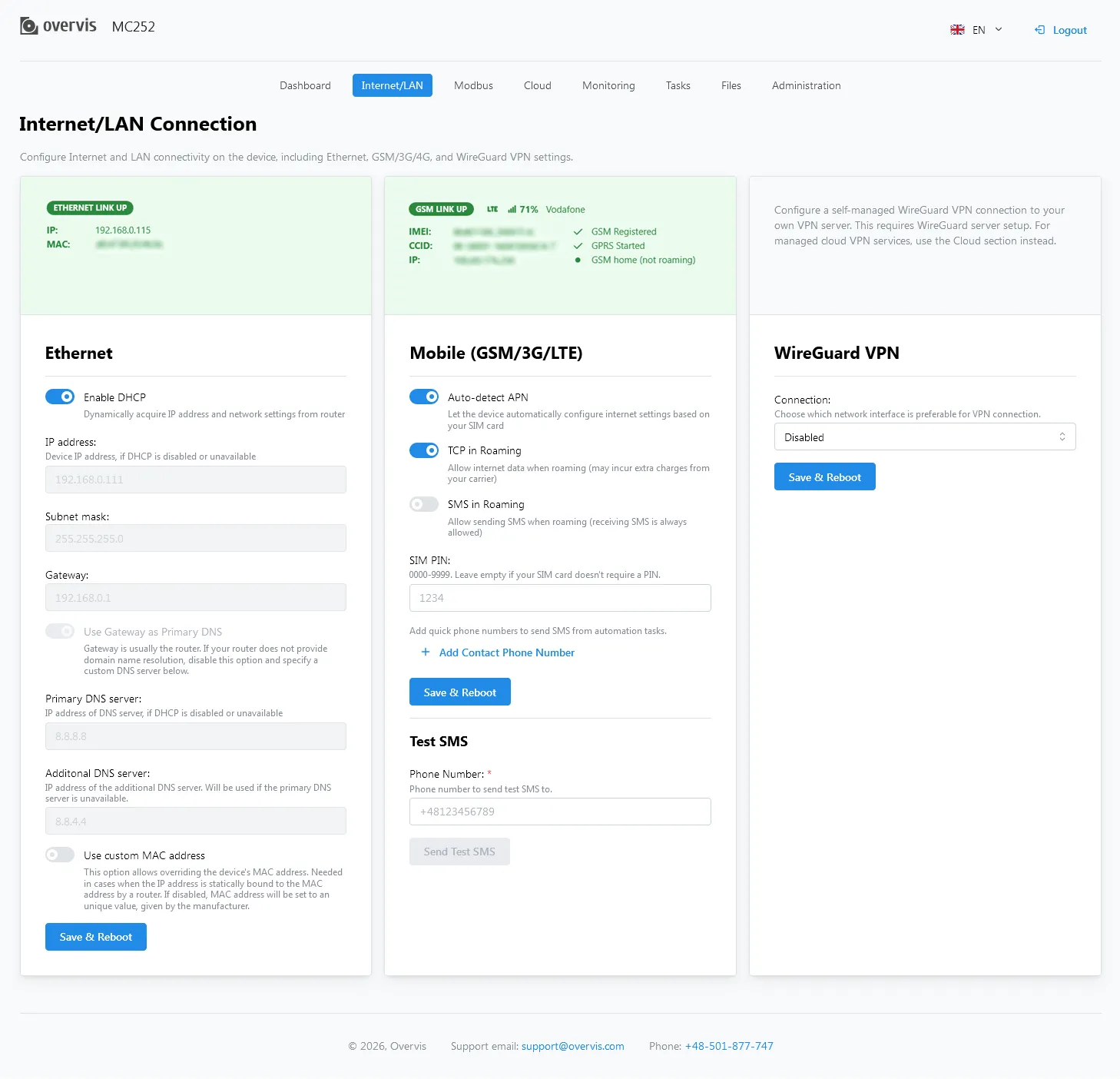 Fig. 3 - The LAN/Internet configuration page
- Ethernet: Configure IP addresses, subnets, and gateways.
- GSM: Configure APN settings, roaming options, PIN code, and quick phone numbers.
- VPN: Set up a WireGuard VPN client. VPN IP addresses can be used in place of Ethernet addresses for routing.
Note: Manual VPN configuration is disabled if the cloud connection is in WireGuard mode. To re-enable the manual settings, switch the cloud connection into Modbus mode or turn it off.
Tip: Leave the private key setting empty to use the device’s unique private key. The corresponding public key can be copied here to be used later on the peer side.
Modbus
Section titled “Modbus”Manage Modbus protocol settings for industrial communication.
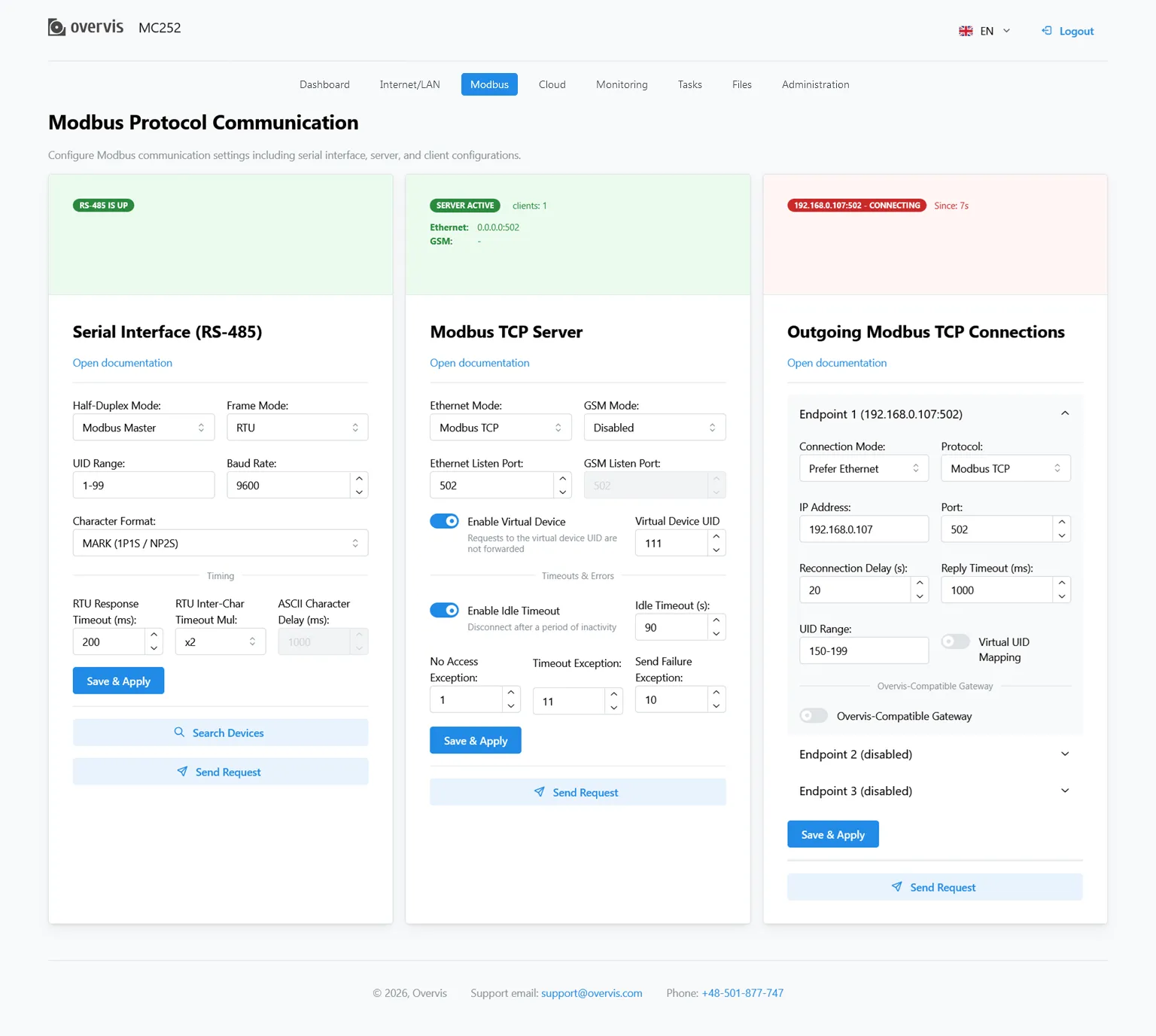 Fig. 4 - The Modbus configuration page
- RS-485: Configure serial interface parameters (mode, baud rate, parity, etc.).
- Modbus TCP Server: Allow incoming connections from Modbus clients (masters).
- Modbus TCP Client: Configure connections to remote Modbus servers (slaves).
- Tunnel Mode: Enable transparent data tunneling for specific directions to bypass protocol conversion, or for non-Modbus transfers.
Note: Modbus settings can often be applied immediately without a full device restart, though the connections will briefly reset.
RS-485 Modbus Devices Search
Section titled “RS-485 Modbus Devices Search”The Search Devices button allows to list the slave devices connected via serial RS-485 interface.
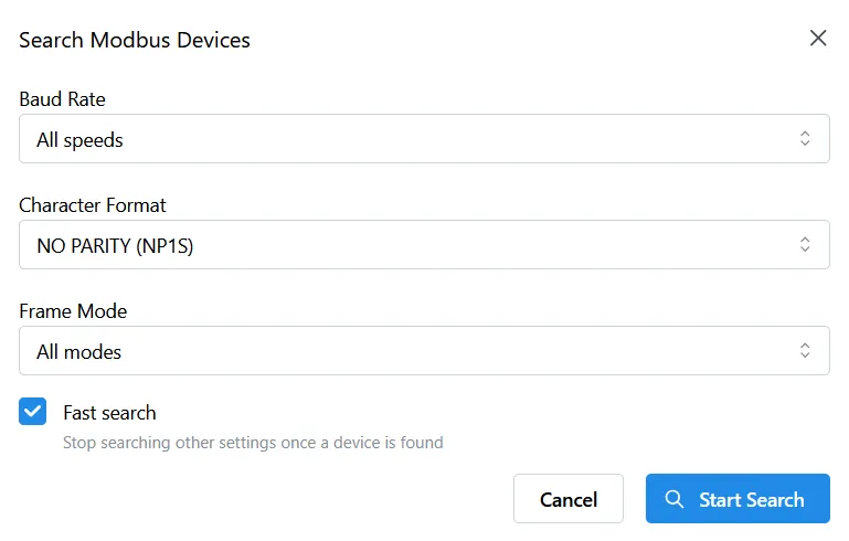 Fig. 5 - The Search Devices tool options
The search covers all the Modbus unit addresses. The search can also cover RTU or ASCII framing and commonly used configurations (baudrate, parity and stopbits), or some of the parameters can be set fixed (to filter and speedup the search).
The search can be optionally simplified to stop matching the configuration once the first device answers on the RS-485 bus. If there is a set of devices with the same serial settings (or a single slave device on the bus), the Fast search option can be flagged. If the number and configuration of the devices are unknown, it is recommended to run a thorough search once (can take from half an hour to an hour).
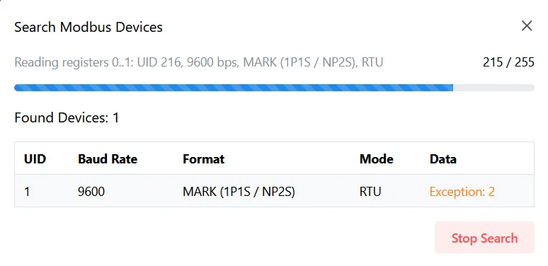 Fig. 6 - The devices search progress
After the search has been started, its progress and the current action are displayed, along with the list of the found devices. For each device, there are shown:
- Modbus unit address (UID);
- the MC252 configuration which has matched;
- the data or the exception code returned by the device.
The exception code during the search does not mean a certain device problem (in most cases the device just didn’t have the Modbus resources requested). The exception still means the device has received the MC252 request and has answered.
The search can be stopped by pressing the stop button or by closing the search tool.
The MC252 configuration is left unchanged by the search. If the needed device configuration differs, either it has to be configured to match the MC252, or the MC252 serial settings have to be manually matched with this device.
Modbus Communication Check
Section titled “Modbus Communication Check”The Send Request button allows to check the MC252 configuration or to check the available Modbus devices (both at RS-485 and at remote TCP servers).
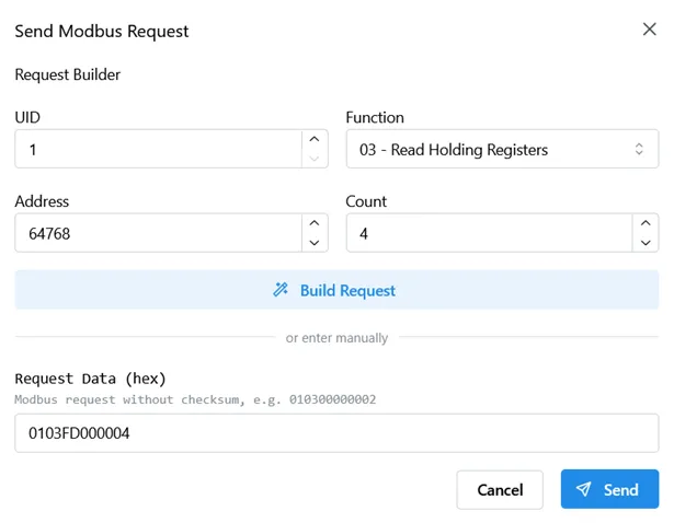 Fig. 7 - The Send Request tool options
The MODBUS request (with device address byte, but without any other headers or checksums) can then be entered as a hexadecimal string of bytes.
The request can also be built by specifying a device Modbus address (UID), function to call and function parameters. These include address (e.g. holding register address) and count of items to read (or a single value to write).
The Build request button would convert the specified parts into a hexadecimal string below. This should be used before sending the request.
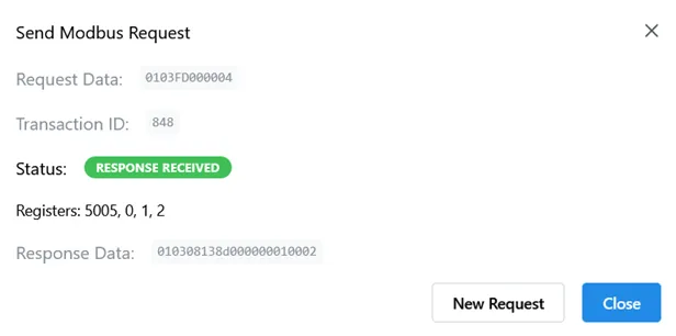 Fig. 8 - The Modbus request results
After the request has been sent, the answer wait message and then the results are displayed. These could be one of the following:
- read data values;
- write success confirmation;
- an exception or an error.
Setup the connection to the Overvis cloud platform.
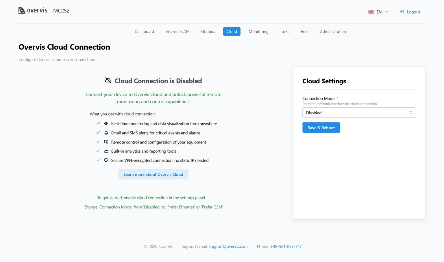 Fig. 9 - The cloud connection configuration page
- Connection: Select the connection method and server address.
- Activation: Link the device to your cloud account.
Monitoring
Section titled “Monitoring”Setup the parameters logging task.
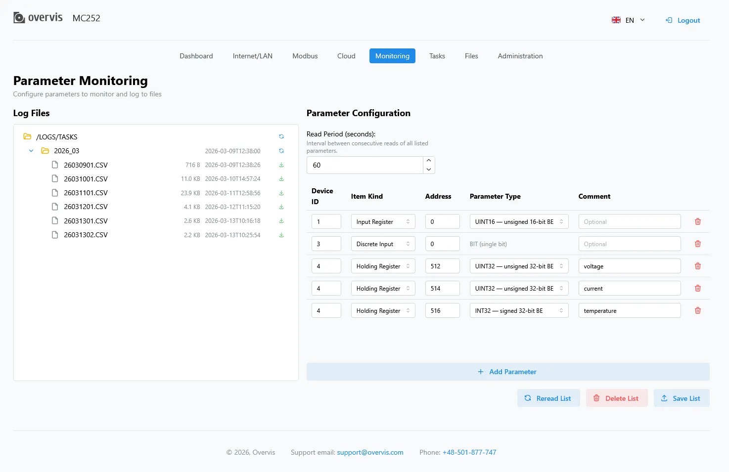 Fig. 10 - The monitoring setup page
The factory default configuration includes no monitoring task.
If the memory card is present, the monitored parameters can be added to the list on the right. Each parameter has an address on a Modbus device and the value type (the way it would be converted from the device registers). The optional comment can be added.
The Save list button allows to generate the automation task /TASKS/PARAMLOG.TXT and then reload the tasks.
The saved parameters log files would be displayed on the left of the page. A folder would be created for each month. Selecting the folder allows to expand it and show the files. The needed file can then be downloaded by pressing the corresponding button to the right of it.
The Delete list button allows to remove the automation task and then restart the tasks for the changes to take effect.
The Reread list button allows to cancel any unsaved changes and read the list from the automation task /TASKS/PARAMLOG.TXT.
Manage programmed logic and automation tasks.
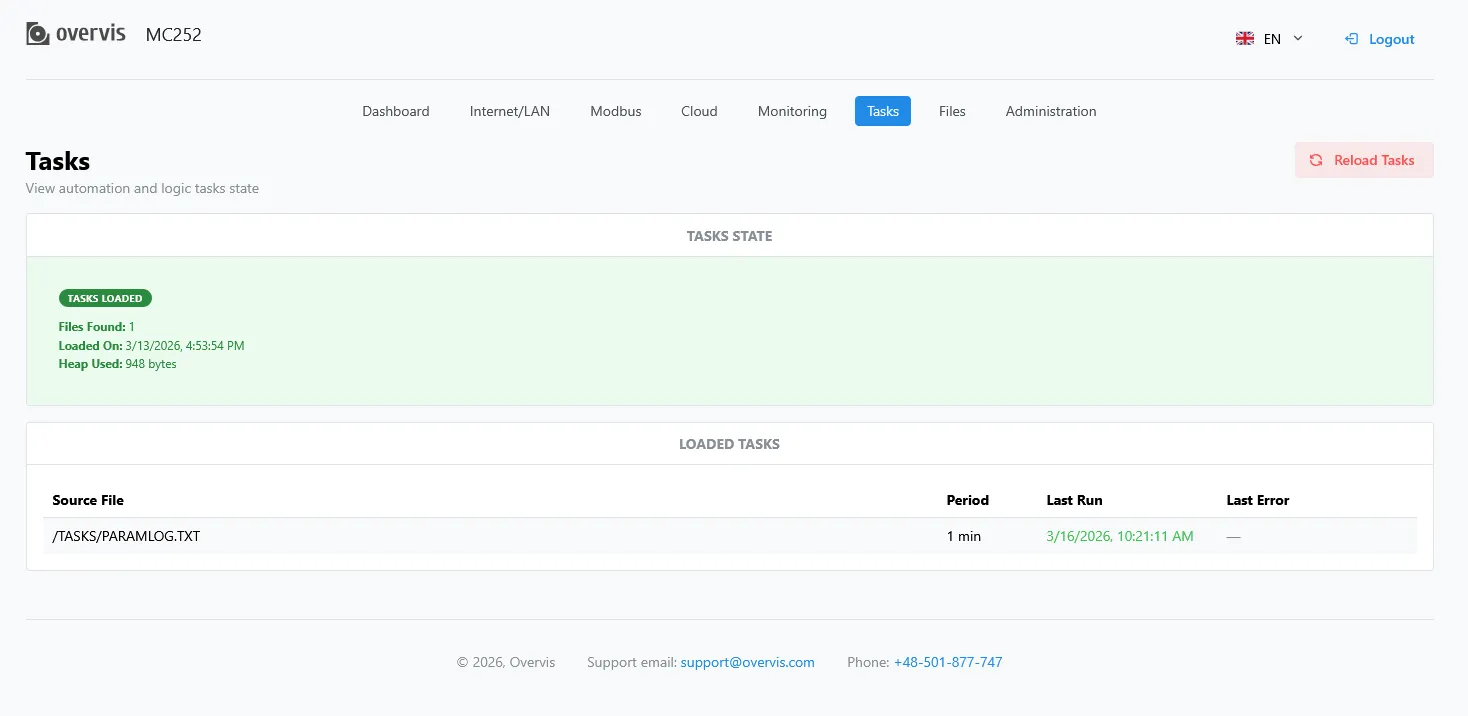 Fig. 11 - The tasks management page
The factory default configuration includes no logic tasks.
If the memory card with taskfiles in the TASKS folder is present, the tasks would be read into the internal memory (see Logic Programming).
This page indicates the result of reading the folder TASKS, including the number of discovered files.
If during reading and verifying the program errors were detected, then it indicates the type of error, file and line number of the file error. If the program consisted of several files in the folder TASKS, then the internal memory will read all files except those in which errors are detected. Therefore, during error correction you should reread tasks, to clear again the internal memory.
The successfully read files are displayed below in the logic tasks table. The original taskfile name, the task programmed period of reruns, the task last run time, and the last run error, if any, are displayed for each of the tasks. If the task was recently run, the last run time is displayed in green. If the task hangs or otherwise misses its scheduled runs, the last run time is displayed in red.
The Reload Tasks button allows to clear the internal tasks memory and then reload the tasks (if the memory card is present).
Manage the contents of the inserted memory card.
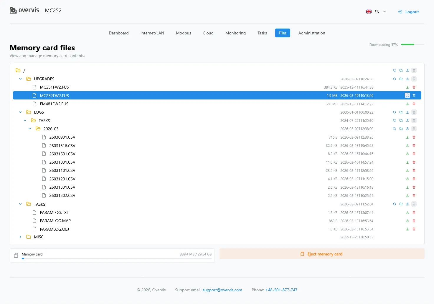 Fig. 12 - The memory card page
Folders can be opened and items can be selected in the tree view of the card contents.
There are options for a folder to re-read its contents, create a new subfolder, upload a file from the local device, remove a folder (provided it is empty). Files have options for download or removal.
The Eject Memory Card button allows to safely remove the card.
If the card is not removed within 30 seconds, it would be automatically re-mounted.
Administration
Section titled “Administration”General system maintenance and device settings.
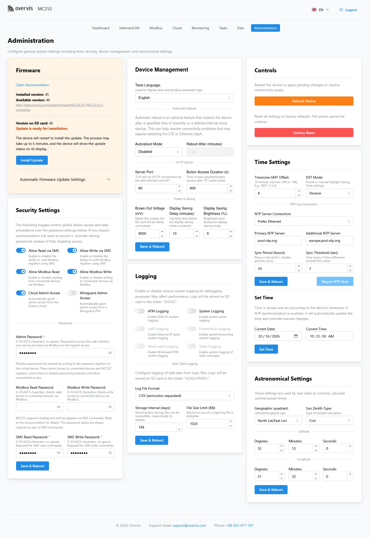 Fig. 13 - The administration page
- Firmware: Perform firmware upgrades.
- Security: Change passwords and access settings.
- Logging: Configure system log options and Modbus parameters log format.
- Service controls: Device soft or hard reset.
- System Time: Configure the internal clock.
- Device management: Configure general miscellaneous settings.
Need Help?
Section titled “Need Help?”For technical support and assistance:
- Email: support@overvis.com
- Support portal: www.overvis.com/support