

Connections and Network Setup
Ta treść nie jest jeszcze dostępna w Twoim języku.
IP Addressing
Section titled “IP Addressing”The Overvis MC261 uses standard TCP/IPv4 addressing for Ethernet and Wi-Fi communication.
DHCP is enabled by default, allowing the device to automatically obtain network settings from your router.
Without DHCP the factory default Ethernet IP address is 192.168.0.111.
IP Addressing Fundamentals
When devices communicate over an Ethernet or Wi-Fi network using the TCP/IPv4 protocol, each device uses IP addressing settings to identify the sender and receiver of data. MC261 stores the following in its memory:
- IP Address: A unique address within the subnet (four bytes written as integers 0-255, separated by dots)
- Subnet Mask: Identical for all devices within the subnet (written similar to IP address)
- Gateway Address: Used to communicate with other networks
Requirements for Proper Communication:
Devices within a subnet communicate properly when these conditions are met:
- Common Subnet Mask: All devices in the subnet must use the same mask. Most small LANs use
255.255.255.0. - Valid Mask Format: The mask starts with consecutive
1bits, followed by consecutive0bits. - Subnet Address: All IP address bits corresponding to the mask’s
1bits must be identical across all devices. Common LANs use192.168as the address prefix with mask255.255.255.0. The third byte can serve as a subnet number in complex LANs; in smaller LANs, it’s typically0. - Unique Host Address: The IP address bits corresponding to the mask’s
0bits must be unique to each device within the subnet. - Gateway Configuration: A router or gateway device that communicates with other networks typically uses an address like
192.168.0.1,192.168.0.100, or192.168.0.101. Other devices can use this address as their gateway. The gateway address is not required for intra-subnet communication—only for connecting to external networks (such as the Internet).
Table 1 - Factory addressing settings for MC261
| Parameter | Value |
|---|---|
| Addressing using DHCP | Yes |
| IP Address | 192.168.0.111 |
| Subnet Mask | 255.255.255.0 |
| Gateway | 192.168.0.1 |
Ethernet Connection Methods
Section titled “Ethernet Connection Methods”With factory default settings, MC261 supports two connection methods via Ethernet.
Method 1: Network with DHCP Server
If your network includes a router or DHCP server that assigns IP addresses to new devices:
- Connect MC261 to the network
- Wait for the device to obtain an IP address (appears on the display with
(E)prefix for Ethernet) - If the display shows
0.0.0.0, the address has not been received yet - If
192.168.0.111appears after 20-60 seconds, DHCP acquisition failed and the device switched to its static address
Method 2: Direct Connection or Network Without DHCP
If DHCP is unavailable, or MC261 is connected directly to a computer:
- MC261 will switch to static addressing after 20-60 seconds
- Configure the client device with:
- Subnet mask:
255.255.255.0 - IP address:
192.168.0.X(where X = 1-254, excluding 111) - Ensure the chosen address doesn’t conflict with other devices on the subnet
- Subnet mask:
If your network uses different addressing (different mask or IP range from Table 1), or if 192.168.0.111 is already taken:
- Temporarily disconnect the conflicting device from the network
- Establish direct communication between your client device and MC261
- Configure both devices for proper network communication
- Reconnect to the network
Configuring Ethernet Connection on Windows PC
Section titled “Configuring Ethernet Connection on Windows PC”In some cases you may need to connect MC261 directly to your computer to access its web interface and change settings. Connect the device with an Ethernet cable to the LAN port on your PC, then configure your network adapter as described below.
The following example shows how to configure a Windows PC (Windows 7/8/10/11) to communicate directly with MC261 using factory settings. For other operating systems, configure your client device’s addressing according to its documentation.
How to access network adapter settings on Windows 7 / 8 / 10
- Log in as administrator
- Select
Start→Control Panel - If items are categorized, select
Network and Internet - Go to
Network and Sharing Center - In the left sidebar, select
Change adapter settings
How to access network adapter settings on Windows 11
- Log in as administrator
- Select
Start→Settings - Select the
Network and Internetcategory - Expand
Advanced Network Settings - Select
More network adapter options
Configuring the Network Adapter
Section titled “Configuring the Network Adapter”-
In the Connections window, select the desired network adapter. If multiple connections appear, choose the correct one by adapter name or consult your system administrator.
-
Right-click the connection icon and select
Properties. The Properties window opens (Fig. 1).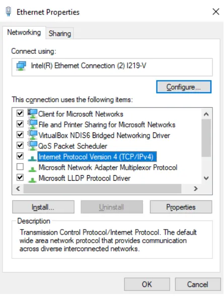
Fig. 1 – Connection properties window in Windows
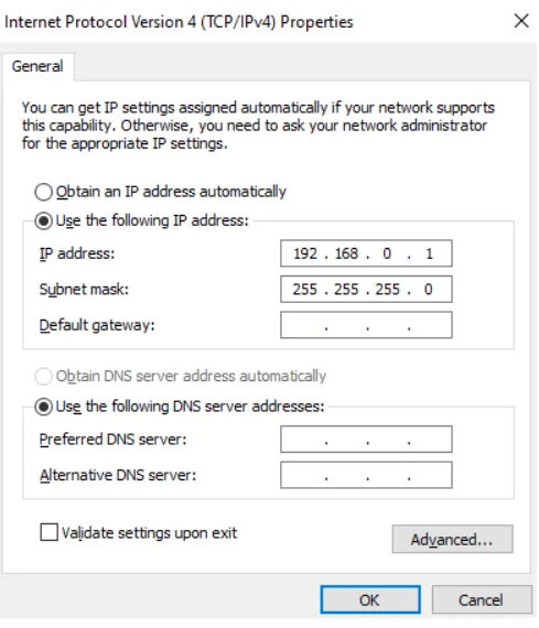
Fig. 2 – TCP/IPv4 properties window in Windows
-
Select
Internet Protocol Version 4 (TCP/IPv4)from the component list. Ensure it’s enabled (checkbox is checked). ClickProperties. The TCP/IPv4 properties window opens (Fig. 2). -
Select
Use the following IP address -
In the
IP addressfield, enter an address in the range192.168.0.1to192.168.0.254(excluding192.168.0.111, which MC261 uses) -
In the
Subnet maskfield, enter255.255.255.0 -
Leave
Default gateway,Preferred DNS server, andAlternate DNS serverfields blank or unchanged -
Click
OKto close the Protocol Settings window -
Click
OKto close the Connection Settings window -
If prompted to restart the PC, select
Yes
Internet Connection via Ethernet
Section titled “Internet Connection via Ethernet”Basic Internet Setup
Section titled “Basic Internet Setup”To connect MC261 to the Internet via Ethernet:
- Connect MC261 to a local network router with DHCP addressing enabled
- Ensure the router is connected to your Internet service provider (ISP)
- Do not connect MC261 directly to the ISP’s cable
This setup enables outgoing connections (e.g., active-mode connection to cloud servers, connections to other servers using hostnames or static IP addresses).
graph LR
    A[MC261] -->|Ethernet| B[Router]
    B -->|WAN| C[Internet/ISP]
    B -->|LAN| D[Local Network]
    C --> E[Cloud Server / Remote Modbus TCP Devices]
    D --> F[Modbus TCP Devices]
Fig. 3 – MC261 Internet connection topology via Ethernet with DHCP
Incoming Connections Setup
Section titled “Incoming Connections Setup”To access the device from the Internet via incoming connections (direct TCP connection or web interface):
-
Acquire a Static IP: Get a dedicated line with a static IP address from your ISP
- Connect the ISP cable to the router’s uplink port (usually color-coded, see router documentation)
- Use a straight-through Ethernet cable to connect MC261 to the router
-
Configure Router: Following your ISP’s recommendations, configure the router for Internet access using the router documentation.
-
Set Up Port Forwarding: Configure the router to redirect queries from your static public IP address to MC261’s local IP address (factory default:
192.168.0.111)- For web interface access: redirect to port 80 on MC261’s local address
- For Modbus TCP or tunnel access: redirect to the incoming Ethernet connections port (register 450, factory default: 502). See Modbus Interface for register configuration details.
graph LR
    A[Internet Client] -->|Public IP:Port| B[Router]
    B -->|Port Forward| C[MC261]
    C -->|RS-485| D[Modbus Devices]
Fig. 4 – MC261 incoming connections via port forwarding
-
Configure DHCP Reservation: Either:
- Configure the router to always assign the same IP address to MC261 via DHCP, OR
- Disable DHCP in MC261 settings and use a static IP
This ensures port forwarding works correctly.
-
Verify Security: Confirm that MC261’s Internet connection is protected by standard security measures (see Connection Security). Specifically, set the write access password to some unique values. It is also recommended to set the read access password.
-
Access the Device: When accessing MC261 from the Internet, use the static IP address provided by your ISP and the public port specified in your port forwarding configuration
Wi-Fi Connection Methods
Section titled “Wi-Fi Connection Methods”MC261 needs to be configured for Internet Wi-Fi connectivity. It supports three connection methods via Wi-Fi.
Method 1: Joining a network with DHCP Server (recommended for most users)
If your network includes an access point with DHCP that assigns IP addresses to new devices:
- Configure MC261 with the access point’s SSID and password, save and reboot the device
- Wait for the device to obtain an IP address (appears on the display with
(W)prefix for Wi-Fi) - If the display shows
0.0.0.0, the address has not been received yet
Method 2: Joining the network without DHCP
If DHCP is unavailable:
- Configure MC261 with the access point’s SSID and password
- Disable DHCP in MC261 settings, then setup its IP address, mask and gateway
- Save and reboot the device
Method 3: Access point mode
For initial setup, instead of configuring via the Ethernet:
- Select the access point mode by pressing the
Rbutton for 6 seconds, then releasing it (when the display prompts to release the button in order to switch the AP mode on) - Join your other device to the MC261 access point with the
MC261_XXXXXXSSID, and setup mode password (default is on the device label) - Connect to the
192.168.4.1with the browser to configure MC261 - Configure the device (SSID and password of the Wi-Fi and Internet access point), then
Save & Reboot. The device should turn off the access point mode and connect to the specified SSID
Internet connection is basically the same as for Ethernet, but the device must be connected to a Wi-Fi access point with Internet access.
Connection Security
Section titled “Connection Security”MC261 provides several security features to protect against unauthorized access:
Built-in Security Features
Section titled “Built-in Security Features”MC261 has basic protection against unauthorized access via network. Access for writing and/or reading via Modbus can be deactivated in settings.
Device settings can be changed remotely by entering a password (minimum 5 characters). Access passwords can be set for restriction of writing and/or reading via Modbus.
When entering the password, all settings are only available to the specific client using the specific protocol. In case of no requests from the client over a long period, the access returns to locked mode.
Server Connection
Section titled “Server Connection”MC261 supports constant communication with data collection and management servers, for example, Overvis Cloud.
MC261 factory settings are preconfigured for Overvis connection, but the connection is disabled by default and must be enabled manually.
The Overvis system uses MAC address-based authentication — the device’s unique MAC address is sent to the server at each connection session.
Connection Methods Overview
Section titled “Connection Methods Overview”There are three ways to connect MC261 to Overvis Cloud:
-
Using PIN/QR Code from Label (Recommended for first-time setup) — The fastest method using reverse connection where MC261 connects to Overvis. Simply scan the QR code on your device label. Detailed in Quick Start Guide.
-
Using Activation Code (Requires physical access) — Uses reverse connection with an 8-digit code displayed on the MC261 screen and web interface. This method proves physical device access, making it suitable for taking over previously used devices, verifying ownership, or when the label is unavailable.
-
Direct Connection from Overvis (For advanced users) — Overvis connects directly to MC261 through router port forwarding, requiring a static public IP address. Used rarely due to complexity and security considerations.
Method 1: Using PIN/QR Code from Device Label
Section titled “Method 1: Using PIN/QR Code from Device Label”This is the recommended method for first-time setup, using the registration information from your MC261 label.
sequenceDiagram
    participant MC261
    participant Overvis
    participant User

    MC261->>Overvis: Connect & send handshake (MAC address)
    Overvis->>MC261: Confirm handshake
    Note over MC261,Overvis: Connection established, waiting for binding

    User->>Overvis: Scan QR code / Enter PIN URL
    User->>Overvis: Login to account
    User->>Overvis: Submit PIN in "Create Network" page
    Overvis->>Overvis: Link PIN to MAC address
    Overvis->>Overvis: Find matching connection by MAC
    Overvis->>User: Create network under user's account

    loop Data Communication
        User->>Overvis: Request device data
        Overvis->>MC261: Read registers (via established connection)
        MC261->>Overvis: Return data
        Overvis->>User: Display data
    end
Fig. 6 – Connection sequence for PIN/QR code method (reverse connection)
Connection Flow: MC261 initiates outbound connection to Overvis and maintains it. User registers by linking the PIN to this existing connection. No port forwarding required.
Prerequisites:
- MC261 connected to Internet (via Ethernet or Wi-Fi)
- QR code label on device (or PIN code from label)
- Overvis Cloud account (or create during setup)
Connection Steps:
-
Verify Internet Connection
Ensure MC261 is connected to the Internet. Check the device display for a valid IP address—the prefix
(E)indicates Ethernet connection,(W)indicates Wi-Fi. Address should not be0.0.0.0. -
Access Overvis Server
Scan the QR code on the device label with your phone or tablet, OR manually enter the URL from the label (format:
https://c.overvis.com/ABCD1234). The link automatically redirects to Overvis server login page with the PIN embedded in the URL. -
Login or Create Account
If you have an account, enter your credentials. New users should register for a free account first.
-
Create Network
After login, Overvis displays the “Create Network” page. If you came from the QR code/link, the PIN is pre-filled automatically. Otherwise, manually enter the PIN from the device label. Click “Check connection” to verify MC261 is online.
-
Configure Network
Give your network a descriptive name (a “network” represents your MC261 plus all connected Modbus devices). MC261 itself (Modbus unit ID 111) is added automatically. Add your RS-485 devices by selecting models and entering their Modbus addresses.
-
Verify Operation
Open a device page in Overvis and read parameters to confirm real-time communication.
After successful registration, the MC261 display will show either active or no code:
┌─────────────────────┐│ ││ Server: ││ (E) no code │└─────────────────────┘Fig. 7 – Status displayed after PIN/QR code activation
Method 2: Using Activation Code
Section titled “Method 2: Using Activation Code”This method requires viewing the MC261 device screen or web interface, proving you have physical access to the device. It’s the primary method for taking over previously used devices and verifying ownership. The activation code also serves as a security measure—only someone with physical access can see and use it.
sequenceDiagram
    participant MC261
    participant Overvis
    participant User

    MC261->>Overvis: Connect & send handshake (MAC address)
    Overvis->>Overvis: Generate random 8-digit Activation Code
    Overvis->>Overvis: Store AC-MAC link
    Overvis->>MC261: Send Activation Code
    MC261->>MC261: Display AC on screen & web interface
    Note over MC261,Overvis: Connection established, waiting for binding

    User->>Overvis: Login to account
    User->>MC261: Read AC from display/web interface
    User->>Overvis: Enter Activation Code
    Overvis->>Overvis: Verify AC-MAC link
    Overvis->>Overvis: Find matching connection by MAC
    Overvis->>User: Create network under user's account
    Overvis->>MC261: Confirm binding
    MC261->>MC261: Display "active"

    loop Data Communication
        User->>Overvis: Request device data
        Overvis->>MC261: Read registers (via established connection)
        MC261->>Overvis: Return data
        Overvis->>User: Display data
    end
Fig. 8 – Connection sequence for Activation Code method (reverse connection)
Connection Flow: MC261 initiates outbound connection to Overvis and receives a unique 8-digit Activation Code. User enters this code to bind the device to their account. No port forwarding required.
Prerequisites:
- MC261 connected to Internet (via Ethernet or Wi-Fi)
- Overvis Cloud account
Connection Steps:
-
Connect to Internet
Connect MC261 to the Internet using one of the methods described in Internet Connection via Ethernet or Wi-Fi Connection.
-
Verify Connection and Get Code
Confirm that the server connection is established and obtain the 8-digit activation code by checking the device display OR the MC261 web interface status page (Cloud tab).
┌─────────────────────┐│ ││ Server: ││ (E) 38571098 │└─────────────────────┘Fig. 9 – Activation code displayed on device screen
The prefix indicates connection method:
(E)for Ethernet,(W)for Wi-Fi -
Create network in Overvis and provide Activation Code
Log in to your Overvis Cloud account at www.overvis.com. On the “Create Network” page, enter the 8-digit activation code to bind the device to your account.
-
Configure Network
Give your network a descriptive name (a “network” represents your MC261 plus all connected Modbus devices). MC261 itself (Modbus unit ID 111) is added automatically. Add your RS-485 devices by selecting models and entering their Modbus addresses.
-
Verify Activation
After successful activation, the MC261 display will show
active:┌─────────────────────┐│ ││ Server: ││ (E) active │└─────────────────────┘Fig. 10 – Activation status displayed on device screen
Method 3: Direct Connection from Overvis
Section titled “Method 3: Direct Connection from Overvis”This method allows Overvis to connect directly to your MC261 using its public IP address. It requires more advanced network configuration.
sequenceDiagram
    participant User
    participant MC261
    participant Router
    participant Overvis

    User->>Router: Configure port forwarding<br/>(Public IP:Port → MC261:502)
    User->>MC261: Set static/reserved IP
    User->>Overvis: Add network with direct connection method
    User->>Overvis: Enter public IP & port
    Overvis->>Router: Connect to Public IP:Port
    Router->>MC261: Forward to MC261:502
    MC261->>Router: Modbus TCP response
    Router->>Overvis: Forward response
    Overvis->>User: Show device online
    loop Data Communication
        User->>Overvis: Request device data
        Overvis->>Router: Read registers request
        Router->>MC261: Forward request to MC261:502
        MC261->>Router: Return data
        Router->>Overvis: Forward response
        Overvis->>User: Display data
    end
Fig. 11 – Connection sequence for direct connection method (incoming connection)
Connection Flow: Overvis initiates inbound connection to MC261 through router port forwarding. Requires static public IP.
Prerequisites:
- Static public IP address from your ISP
- Router with port forwarding capability
- MC261 connected to your LAN
- Overvis Cloud account
- Basic understanding of router configuration and network security
Connection Steps:
-
Obtain Static Public IP
Contact your Internet Service Provider to obtain a static public IP address for your location. Dynamic IP addresses are not recommended as they may change. Some ISPs offer static IP as a paid add-on service.
-
Configure Router Port Forwarding
Access your router’s configuration interface and set up port forwarding to redirect external connections to MC261. Forward to MC261’s Modbus TCP port (default: 502). External port can be the same (502) or different for security. Forward to MC261’s internal IP address (e.g.,
192.168.0.111).graph LR A[Overvis Cloud] -->|Public IP:Port| B[Router] B -->|Port Forward to 192.168.0.111:502| C[MC261] C -->|RS-485| D[Modbus Devices]Fig. 12 – Direct connection port forwarding configuration
-
Configure DHCP Reservation or Static IP
Ensure MC261 always has the same internal IP address:
- Option A: Configure your router to assign MC261 a reserved IP via DHCP (recommended)
- Option B: Disable DHCP on MC261 and manually configure a static IP address in the web interface
-
Verify MC261 Accessibility
Test the connection from outside your network. Use a Modbus TCP client from a different network (e.g., mobile hotspot), connect to your public IP address on the forwarded port, and try reading a register from MC261 (unit ID 111, register 1 for firmware version).
-
Configure Security (Strongly Recommended)
Set strong Modbus TCP passwords in MC261 web interface. Consider changing the external port to a non-standard number. Enable Modbus TCP access logging in MC261 settings. Configure your router’s firewall to restrict access by IP range if possible. See Connection Security for additional recommendations.
-
Create Network in Overvis
Log in to your Overvis Cloud account at www.overvis.com. On the “Create Network” page, select the direct connection method. Enter your static public IP address and the external port number (as configured in router). Enter MC261’s Modbus address (default: 111) and Modbus password if configured.
-
Configure Network
Give your network a descriptive name (a “network” represents your MC261 plus all connected Modbus devices). MC261 itself (Modbus unit ID 111) is added automatically. Add your RS-485 devices by selecting models and entering their Modbus addresses.
-
Verify Operation
Open a device page in Overvis and read parameters to confirm real-time communication. Monitor connection stability over 24-48 hours.
Connecting to Other Servers
Section titled “Connecting to Other Servers”The only method of connection MC261 to other cloud servers and SCADA systems is the direct connection method via Modbus TCP (although it can be used over Wireguard VPN tunnel).
In case of direct connection, configure MC261 in the monitoring system as a remote Modbus TCP device. This requires setting up port forwarding on your router to redirect external connections to MC261’s local IP address and Modbus TCP port (default: 502). Your server will initiate connections to MC261 through your router, similar to Method 3 described above. You’ll need a static public IP address from your ISP, or alternatively, you can use a secure WireGuard VPN tunnel to bypass the need for public IP exposure.
Since MC261 uses the standard Modbus TCP protocol for direct connections, no special server software is required — any Modbus TCP client can communicate with the device. See the Modbus Interface documentation for complete register mappings and communication protocols.
Troubleshooting
Section titled “Troubleshooting”Problem: MC261 display shows 0.0.0.0
The DHCP server is not responding.
Wait up to 60 seconds for MC261 to switch to its static Ethernet IP 192.168.0.111.
If the issue persists, verify the network cable is properly connected and check your router’s DHCP settings.
Problem: Cannot access MC261 web interface
Verify your client device is on the same subnet as MC261.
Check firewall settings on your client device and confirm the MC261 Ethernet IP address shown on the display.
You can press the R button briefly to grant temporary password-free access.
Problem: LAN LED is off
Check the Ethernet cable connection and verify it’s not damaged. Try using a different cable to rule out cable faults.
Problem: Wi-Fi LED intermittently blinks (rarely)
The Wi-Fi SSID and password should be configured properly before using the Wi-Fi module. Check the access point is available. Poor signal strength may require relocating MC261.
Problem: SRV LED stays off
MC261 is not connected to the Internet — check your Ethernet or Wi-Fi connection. Verify the server Modbus TCP connection is enabled in the web interface. Check that the server address and port are correct in settings. Your network firewall may be blocking outgoing connections.
Problem: Activation code not displayed
The server connection has not been established yet. Verify Internet connectivity and wait up to 2 minutes after the Internet connection is established. Check the cloud server settings in the web interface.
Problem: “Device already registered” error
The device is bound to another Overvis account. Use the Restart Activation button in the Cloud settings page to unbind it, or contact the previous owner to remove the device from their account.
Problem: Intermittent connection drops
Check that the power supply voltage is within the required range (9-30V DC) and can provide sufficient current (up to 500mA). Look for electrical noise or interference sources near the device. Update MC261 firmware to the latest version.
Problem: RS-485 devices not responding
Verify the RS-485 wiring is correct (A and B terminals). Check that the RS-485 bus termination is properly configured. Verify Modbus RTU/ASCII settings match the connected devices. See the Modbus Interface documentation for detailed communication settings.
Further Reading
Section titled “Further Reading”- Web Interface — Complete guide to MC261’s web-based configuration interface
- Modbus Interface — Register mappings and communication protocols for Modbus TCP/RTU/ASCII
Need Help?
Section titled “Need Help?”If you’re experiencing issues not covered in this guide, we’re here to help:
- Technical Support: Contact the manufacturer’s support team
- Documentation: Visit overvis.com/support for additional resources
- Community: Check the user forums for solutions from other MC261 users
For warranty service or hardware issues, please contact your authorized distributor or the manufacturer directly.