EM-482 Operating Manual
Ta treść nie jest jeszcze dostępna w Twoim języku.
This Operating Manual explains the design, safety requirements, operating rules, and maintenance procedures for the EM-482 and EM-482-1 Protocol Converters (hereinafter referred to as “Protocol Converter”, “Product”, or “EM-482”; the name “EM-482-1” is used when the characteristics differ).
Safety information
Section titled “Safety information”During operation and maintenance, observe the requirements of applicable regulatory documents, including:
- Regulations for Operation of Consumer Electrical Installations;
- Safety Rules for Operation of Consumer Electrical Installations;
- Occupational Safety Rules for Operation of Electrical Installations.
Only qualified personnel who have studied this Operating Manual should perform installation, adjustment, and maintenance.
When used in accordance with this manual, the Overvis EM-482 is safe in operation.
EM-482 meets the requirements of the following standards: EN 60947-1; EN 60947-6-2; EN 55011; EN 61000-4-2.
The device contains no hazardous substances in excess of maximum permissible limits.
The development and production quality management system complies with ISO 9001:2015.
General description
Section titled “General description”The Protocol Converter EM-482 provides MODBUS communication between clients and servers in Wi-Fi TCP networks and between devices at RS-485 interface.
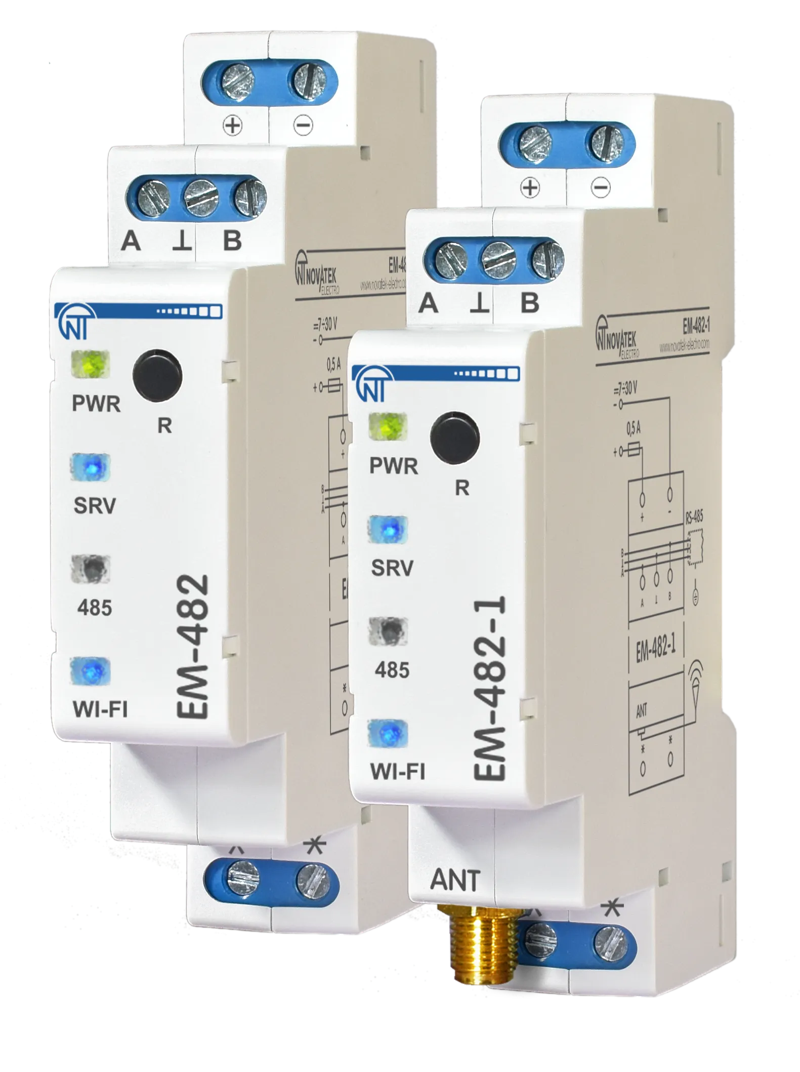
The Product is available in two versions (both with a built-in antenna):
- EM-482 for mounting in conditions with a good Wi-Fi signal (for example, in plastic cases);
- EM-482-1 with additionally included remote antenna for mounting in conditions with a weak Wi-Fi signal (for example, in metal cases).
The Protocol Converter:
- provides access to RS-485 devices data via Modbus TCP;
- provides access to Modbus TCP devices for RS-485 devices;
- transfers data to a server or cloud service.
EM-482 provides the following capabilities:
- Flexible RS-485 communication: Modbus RTU or ASCII, even/odd/no parity, wide range of baud rates, adjustable delays
- Automatic access point switch: A stronger signal access point is selected out of the several points with the same SSID
- Access security: passwords for setup mode and connections to the Modbus network, for reading or writing, connecting only to a selected cloud server
- Firmware update capability: Manual upgrade or a remote command-triggered automatic upgrade
Overall and Mounting Dimensions and Controls
Section titled “Overall and Mounting Dimensions and Controls”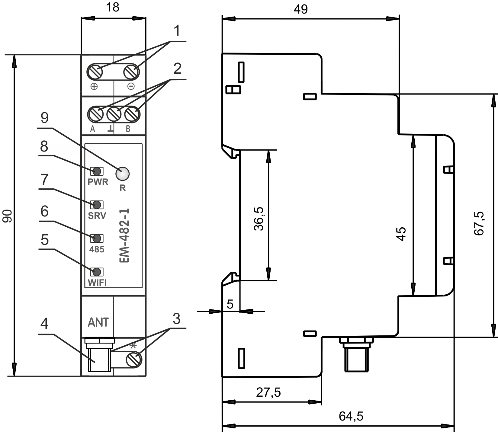
Figure 1 – Overall and mounting dimensions and controls
- The
+and-terminals are designed for power supply connection (from 7 to 30 VDC). - Terminals
A,⊥andBare used for connecting to the RS-485 network connection. - Terminals are not used.
- SMA-F
ANTconnector (only for EM-482-1) is used for connecting a Wi-Fi antenna (included). - The
WI-FIindicator is lit while Wi-Fi is connected, blinks every three seconds when searching for a Wi-Fi network, and blinks alternately with the «SRV» indicator in the Wi-Fi setup mode. - The
485indicator lights up when waiting for transmission over RS-485 and blinks when data are being exchanged over RS-485. - The
SRVindicator lit while the data collection server is connected, blinks when data is being exchanged with the server, and blinks alternately with the «WI-FI» indicator in the Wi-Fi setup mode. - The
PWRindicator is green during normal operation and flashes red when a communication error occurs. - Reset Button
Rmay be used for: entering the Wi-Fi setup mode; restarting the Product; and resetting the parameters to the manufacturer’s defaults.
Operating conditions
Section titled “Operating conditions”EM-482 is designed for operation under the following environmental conditions:
- Ambient temperature: –35 … +45 °С
- Atmospheric pressure: 84 … 106.7 kPa
- Relative humidity (at +25 °С): 30 … 80%
Delivery set
Section titled “Delivery set”Table 1 – EM-482 delivery set
| Item | EM-482 | EM-482-1 |
|---|---|---|
| Protocol converter | 1 pcs. | 1 pcs. |
| Operating manual | 1 pcs. | 1 pcs. |
| Antenna for SMA connector | — | 1 pcs. |
| Packaging | 1 pcs. | 1 pcs. |
Technical Specifications
Section titled “Technical Specifications”Table 2 – EM-482 technical specifications
| Parameter | Value |
|---|---|
| DC rated supply voltage | 7 – 30 V |
| TCP networks link interface | Wi-Fi |
| Wi-Fi Module | ESP8266 (ESP-07) |
| Wi-Fi Module frequency | 2.4 GHz |
| Supported Wi-Fi standards | IEEE 802.11 b/g/n |
| Supported TCP network protocols | DNS, DHCP, Modbus TCP, HTTP |
| Built-in TCP servers | Modbus TCP, HTTP |
| Serial link interface | RS-485 |
| Supported serial protocols | Modbus RTU, Modbus ASCII |
| Short circuit output current of RS-485 driver (maximum) | 250 mA |
| The recommended number of devices connected to the RS-485 bus: | |
| – when the input current of receivers on RS-485 bus is less than 0.25 mA; | ≤ 128 |
| – when the input current of receivers on RS-485 bus is less than 1 mA | ≤ 32 |
| Built-in RS-485 terminator resistance | 1 000 Ω |
| Ready time at power-up | ≤ 2 s* |
| Current consumption (at a supply voltage of 12 V) | ≤ 110 mA |
| Weight | ≤ 0.08 kg |
| Overall dimensions, H×B×L | 90 × 65 × 18 mm |
| The Product designation | Switchgear and control equipment |
| Rated operating condition | Continuous |
| Conductor cross-section for connecting to terminals | 0.3 – 3 mm² |
| Tightening torque of the terminal screws of input contacts | 0.4 N·m |
| Climatic design version | NF 3.1 |
| Electric shock protection class | III |
| Overvoltage category | II |
| Permissible pollution density | II |
| Insulation rated voltage | 450 V |
| Rated pulse withstand voltage | 2.5 kV |
| Installation (mounting) | DIN rail 35 mm |
* Establishing connections in Wi-Fi / Internet networks can take more time.
The Product remains functional at any position in space.
Case material: self-extinguishing plastic.
Installation and wiring
Section titled “Installation and wiring”Before you start:
- Unpack EM-482 (we recommend keeping the original packing for the entire warranty period).
- Check EM-482 for damage after transportation. If you find any damage, contact the supplier or manufacturer.
- Read this Operating Manual carefully (pay special attention to the power supply in the connection diagram).
- If you have any questions regarding installation, contact the manufacturer.
Wiring requirements
Section titled “Wiring requirements”If the temperature of EM-482 after transportation or storage differs from the ambient operating temperature, keep EM-482 under operating conditions for at least two hours before connecting it to the power supply. This prevents condensation on internal components.
To ensure reliable electrical connections, use flexible (stranded) wires. Strip the insulation from the wire ends by 5±0.5 mm and crimp with suitable ferrules. It is recommended to use wire with a cross-section of at least 1 mm².
When connecting to the RS-485 bus, use twisted-pair cable of category 1 or higher. A shielded cable is recommended; in that case, ground the shield according to “ANSI/TIA/EIA-485-A-1998”.
Route and fasten wires so as to avoid mechanical damage, twisting, or abrasion of the insulation.
For a reliable contact, tighten the terminal screws with the force indicated in Technical specifications.
To improve safety and reliability, it is recommended to install the fuse F1 (or its equivalent) in the EM-482 supply circuit, rated for a current of no more than 0.5 A.
Electrical connection
Section titled “Electrical connection”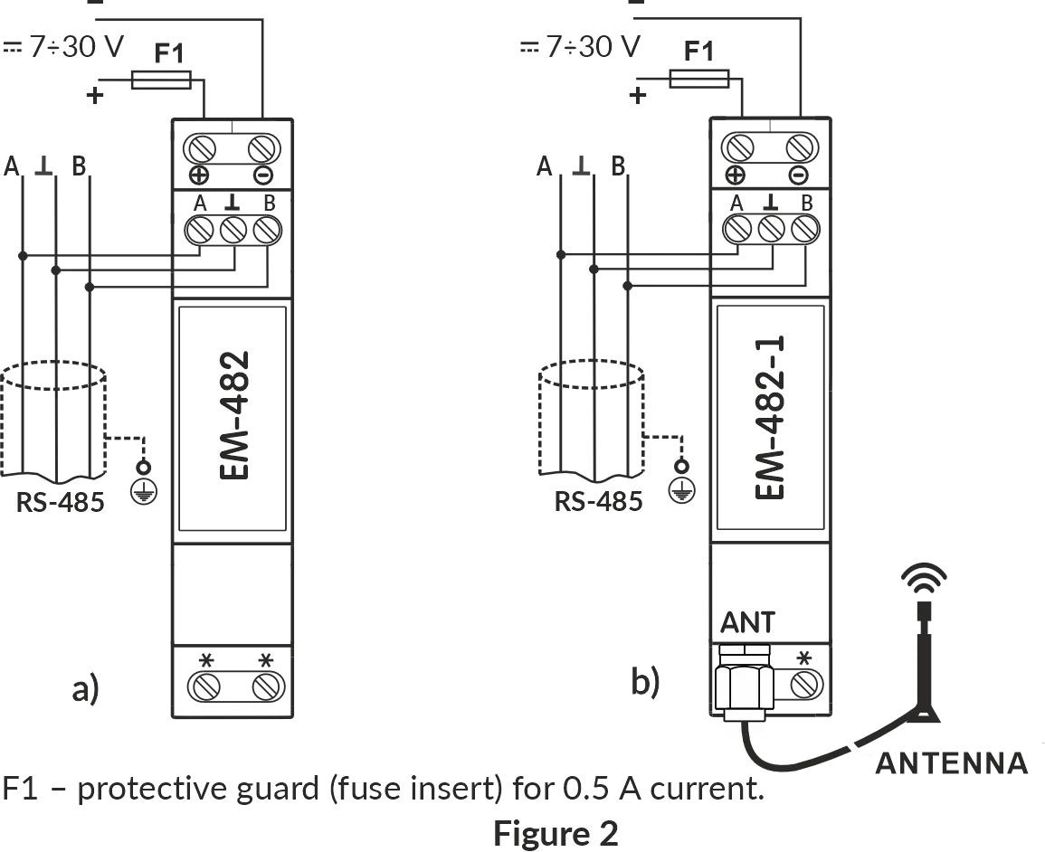
Figure 2 – Connection diagram
F1– fuse (fuse element) rated for 0.5 A;- Contact
A– transmission of non-inverted signal; - Contact
B– transmission of inverted signal.
Follow these steps to connect the EM-482:
- Connect the RS-485 bus cable to the
RS-485terminals (A and B) and to the RS-485 bus (or directly to the device with an RS-485 interface). - For EM-482-1, install the antenna outside of the case, connect the antenna to the
ANTconnector (SMA F connector). - Connect the appropriate DC power supply to the
+and-terminals (7÷30V).
Power-up and normal operation
Section titled “Power-up and normal operation”After power is turned on, all indicators light up, and EM-482 performs initialization.
After approximately 2 seconds, the indicators (except for the PWR indicator, which turns green) go out, and the Product proceeds to start the Wi-Fi network interface.
Startup can take up to 30 seconds.
If the WI-FI indicator lights up, the connection to the network was successful.
The WI-FI indicator blinking every three seconds indicates the process of connecting to the network.
The WI-FI and SRV indicators flashing alternately indicate that the Wi-Fi setup mode (access point) is enabled.
After this, if enabled in settings, EM-482 establishes a connection with the cloud server. By default, cloud connection is enabled.
If configured, EM-482 establishes TCP connections and waits for incoming TCP connections.
Communication modes
Section titled “Communication modes”The EM-482 is a protocol converter that bridges RS-485 Modbus RTU/ASCII networks with Modbus TCP networks. It operates in multiple communication modes simultaneously, providing flexible connectivity through Wi-Fi networks, and RS-485 interface. Each mode serves a distinct purpose and can be used independently or in combination to meet your application requirements.
Connection to cloud server (reverse connection)
Section titled “Connection to cloud server (reverse connection)”EM-482 can establish and maintain a persistent outbound connection to a cloud server (using Modbus TCP protocol).
- EM-482 initiates the outbound connection to the server, bypassing firewall issues
- After connection is established, EM-482 sends its MAC address for identification as a first Modbus TCP packet (response for function 3)
- After that it operates in slave mode, waiting for and processing server requests
- The server sends Modbus requests through this connection
- EM-482 forwards these requests to RS-485 devices or responds with its own register values
- Returns responses back to the server
- If the
SRVLED is on, the connection to the server or VPN has been successfully established - If the
SRVLED blinks, data is being exchanged via this connection
Use case: Centralized monitoring and control of distributed equipment through cloud platforms like Overvis Cloud, enabling remote access from anywhere without configuring firewall port forwarding or static IP addresses.
RS-485 Modbus RTU/ASCII master mode
Section titled “RS-485 Modbus RTU/ASCII master mode”In master mode, EM-482 forwards Modbus requests from TCP clients to devices on the RS-485 bus and returns their responses.
- EM-482 receives Modbus requests from TCP connections (incoming or outgoing)
- Translates Modbus TCP requests to Modbus RTU/ASCII format
- Forwards requests to target devices on the RS-485 network
- Returns responses back to the TCP client
- Supports both Modbus RTU and Modbus ASCII protocols
Request processing is described in detail in Modbus interface.
Use case: Data collection and event tracking for serial port equipment.
Integrated Modbus TCP server (slave mode)
Section titled “Integrated Modbus TCP server (slave mode)”EM-482 acts as a Modbus TCP server, accepting incoming connections and processing Modbus requests.
- Listens for incoming TCP connections from SCADA systems, HMI panels, or other Modbus TCP clients
- Receives Modbus TCP requests from connected clients
- Responds with its own register values or translates requests to Modbus RTU/ASCII and forwards them to RS-485 devices (in master mode)
- Returns responses back to the TCP client
- Supports up to 4 simultaneous incoming TCP connections
- EM-482’s own registers can also be accessed directly (supply voltage, user registers, etc.)
Use case: Access to the RS-485 serial port equipment for the TCP devices, HMI panels, SCADA and other Modbus TCP software.
Connection to remote Modbus TCP server (master mode)
Section titled “Connection to remote Modbus TCP server (master mode)”EM-482 can establish outgoing connection to remote Modbus TCP server, enabling it to forward requests to remote devices.
- Initiates and maintains TCP connection to specified remote Modbus TCP server via Wi-Fi
- Forwards Modbus requests received from other sources (RS-485 master or incoming TCP connections) to the remote server
- Receives responses from the remote server and returns them to the requester
- Enables bridging between local RS-485 network and remote TCP-based Modbus devices
Use case: Data collection and event tracking for Modbus TCP equipment.
Reverse control translator mode (RS-485 slave, TCP master)
Section titled “Reverse control translator mode (RS-485 slave, TCP master)”EM-482 can operate as an RS-485 slave while acting as a Modbus TCP master, enabling reverse control scenarios.
- Receives Modbus RTU/ASCII requests from an RS-485 master device
- Translates these requests to Modbus TCP format
- Forwards them to remote TCP server (or local TCP-based devices)
- Receives responses from TCP devices
- Returns responses back to the RS-485 master in RTU/ASCII format
Use case: Access to the Modbus TCP equipment for the RS-485 serial port master device.
Network extension (long-range RS-485 bridging)
Section titled “Network extension (long-range RS-485 bridging)”Pair two EM-482 units to extend RS-485 networks beyond physical distance limitations by converting to/from TCP.
- One EM-482 operates in master mode on its RS-485 interface, while the other is in slave mode
- First EM-482 receives RS-485 signals and converts them to TCP packets
- Data is transmitted over any distance via TCP/IP networks
- Second EM-482 receives TCP packets and converts them back to RS-485 signals
- Creates a transparent Modbus bridge between two RS-485 networks or segments
- Each EM-482 can operate in master or slave mode on its RS-485 interface as needed
Use case: Connecting RS-485 networks in separate buildings without running long cable runs, extending RS-485 beyond the 1200m distance limit, or accessing remote sites via Internet.
Configuration
Section titled “Configuration”EM-482 configuration can be performed in two ways:
- via the web interface, using a browser to configure the most important parameters in the Wi-Fi setup mode (see Quick Start Guide);
- via the Modbus protocol, using cloud server or any Modbus client software that works with EM-482’s own registers (see Modbus interface).
Use the service R button on the front panel to get into Wi-Fi setup mode, restart the controller, or reset factory settings.
To reset the device to factory settings:
- Press and hold the
Rbutton for at least 8 seconds. After 2 seconds, thePWRindicator will light up red. After 8 seconds, the settings are reset, and the device restarts; all the indicators blink once. - Release the
Rbutton.
To switch Wi-Fi setup mode on or off:
- Press and hold the
Rbutton for 2 to 8 seconds. - When the
PWRindicator lights up red, release theRbutton. - All the indicators blink once, and the device restarts.
To reset the device (while preserving the settings):
- Briefly press and release the
Rbutton. - All the indicators blink once, and the device restarts.
Maintenance
Section titled “Maintenance”- Only qualified personnel should perform maintenance.
- Recommended maintenance interval is every six months.
- Check the reliability of wire connections; if necessary, retighten terminals with the torque specified in Technical Specifications.
- Visually inspect the housing. If you detect cracks or other damage, take EM-482 out of service and send it for repair.
- If necessary, wipe the front panel and housing with a soft cloth.
Service life and warranty
Section titled “Service life and warranty”- The service life of EM-482 is 10 years. After the service life expires, contact the manufacturer.
- Shelf life is 3 years.
- The warranty period is 5 years from the date of sale. During the warranty period, in the event of failure, the manufacturer provides free repair.
- The place of purchase or the manufacturer performs warranty service.
- The manufacturer performs post-warranty service at current rates.
- Before sending EM-482 for repair, pack it in the original or other packaging that protects it from mechanical damage.
When returning EM-482 for warranty or post-warranty service, please provide a detailed reason for the return in the claims data field.
Transportation and storage
Section titled “Transportation and storage”You may transport and store EM-482 in the original package at temperatures from minus 45 to +60 °C and relative humidity of no more than 80%. When transporting EM-482, protect it against mechanical damage.
Manufacturer Contact
Section titled “Manufacturer Contact”“Novatek-Electro” Ltd.
- Website: www.novatek-electro.com
- Address: 59, Mykhailo Boltenko (Admiral Lazarev) str., Odesa, Ukraine, 65007
- Tel: +38 (067) 565 37 68; +38 (050) 359 39 11; +38 (063) 301 30 40