EM-125 Operating Manual
Ta treść nie jest jeszcze dostępna w Twoim języku.

WI-FI CONTROL
MULTIFUNCTIONAL TIMER RELAY
EM-125
OPERATING MANUAL
PASSPORT
Quality management system for product development and manufacturing complies with ISO 9001:2015 requirements
Dear Customer,
NOVATEK-ELECTRO thanks you for purchasing our product.
After carefully studying this Operating Manual, you will be able to use the product correctly. Keep this Operating Manual throughout the entire service life of the product.
Ukraine, Odesa — www.novatek-electro.com
1 Purpose
Section titled “1 Purpose”The multifunctional timer relay EM-125 (hereinafter referred to as the product or EM-125) is a microprocessor device designed for home automation — a smart plug.
EM-125 allows you to turn on/off loads according to a schedule or manually, while simultaneously protecting the load from various voltage emergencies and power overloads.
After registration on the “my.overvis.com” server, control and configuration of EM-125 is possible from anywhere in the world with an internet connection.
EM-125 accumulates energy consumption statistics in real time and sends the accumulated data to the “my.overvis.com” server, allowing you to view saved reports for a week, month, or year.
You can save electricity and reduce your costs by using EM-125 to control heating and ventilation equipment according to a pre-planned schedule.
Main Features
Section titled “Main Features”- Voltage and frequency measurement of the mains
- Measurement of current consumed by the load
- Measurement of power consumed by the load
- Accounting of electricity consumed by the load
- Protection of load from emergency mains voltage
- Protection of load from exceeding consumption current
- Protection of load from exceeding consumption power
- Real-time clock with up to 5-day backup (without power supply)
- Automatic time synchronization with SNTP server
- Automatic load control according to a user-defined schedule
- Vacation planning (with blocking of program execution)
- Load operation time limiting
- Manual load control from the front panel
- Blocking of manual control after a specified time interval (child protection)
Controls
Section titled “Controls”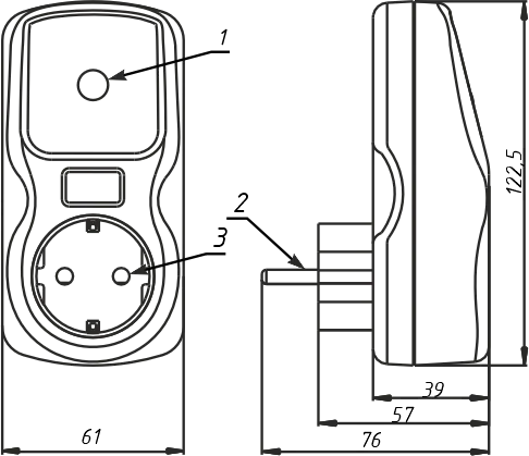
1 — “ENTER” control and indication button
2 — “Plug” — for connecting to the mains
3 — “Socket” — for connecting the load
Figure 1 — EM-125 Controls
”ENTER” Button Indication
Section titled “”ENTER” Button Indication”- Blue (flashing with 0.5 s period) — connecting to Wi-Fi access point
- Blue (on) — load is on
- Blue (off, flashes every 5 seconds) — power is on, load is off
- Red (flashing with 0.5 s period) — automatic reclosing (AR) countdown in progress
- Red (on) — emergency present or device is locked due to emergency
- Blue-red (flashing with 0.35 s period) — Wi-Fi connection setup mode enabled
- Blue-red (flashing with 0.1 s period) — factory reset in progress
- Purple (flashing with 0.1 s period) — firmware update in progress
2 Terms and Abbreviations
Section titled “2 Terms and Abbreviations”Wi-Fi — a set of standards for transmitting digital data streams via radio channel
RMS — Root Mean Square (effective) value
AR — Automatic Reclosing of the load
Default — preset parameter values that the product uses in its operation until the user explicitly changes these values
Web interface — a system for user interaction with the product through a computer browser
Purple — indicator color obtained by mixing blue and red light
3 Technical Specifications
Section titled “3 Technical Specifications”| Parameter | Value |
|---|---|
| Rated supply voltage | 220 – 240 V |
| Mains frequency | 45 – 62 Hz |
| Operating voltage range | 100 – 400 V |
| Maximum switching current with resistive load | 16 A |
| Connected load power | ≤ 3.6 kW |
| Readiness time upon power supply | ≤ 0.4 s |
| Mains voltage measurement accuracy | ±3 V |
| Load current measurement accuracy | ±0.3 A |
| Real-time clock accuracy¹ | ±1 s/day |
| Real-time clock backup² | up to 5 days |
| Wi-Fi frequency | 2.412 – 2.484 GHz |
| Supported Wi-Fi standards | IEEE 802.11 b/g/n |
| Wi-Fi encryption protocol | WPA2/PSK |
| SNTP time synchronization protocol | yes |
| Data exchange protocol with “my.overvis.com” server | yes |
| Maximum number of events (schedule) | 512 |
| Maximum log length | 10,000 records |
| Log record type | circular |
| Log record period | 5 minutes |
| Product purpose | Control and distribution equipment |
| Nominal operating mode | Continuous |
| Climatic version | UHL 4 |
| Device protection rating | IP30 |
| Switching resource of output contacts at cosφ=1: under 16 A load | ≥100,000 times |
| Switching resource of output contacts at cosφ=1: under 5 A load | ≥1,000,000 times |
| Power consumption (under load) | ≤ 2.5 W |
| Permissible pollution degree | II |
| Overvoltage category | II |
| Protection class against electric shock | I |
| Rated insulation voltage | 450 V |
| Rated impulse withstand voltage | 2.5 kV |
| Weight | ≤ 0.16 kg |
| Overall dimensions, H×W×L | see Figure 1 |
The product maintains its functionality in any spatial orientation.
Case material — self-extinguishing plastic.
The product complies with: DSTU EN 60947-1:2017; DSTU EN 60947-6-2:2014; DSTU EN 55011:2017; DSTU EN 61000-4-2:2018.
No harmful substances in quantities exceeding maximum permissible concentrations.
¹ — provided that SNTP server synchronization is enabled
² — provided that the product has been powered from the mains for at least 30 minutes
4 Operating Modes
Section titled “4 Operating Modes”The product can operate in three modes:
- Normal operation mode
- Manual control mode
- Wi-Fi connection setup mode
Normal Operation Mode
Section titled “Normal Operation Mode”EM-125 connects to the user-specified access point, performs measurements and monitors mains parameters (voltage and current) to protect the load according to the user-defined schedule.
In case of an emergency (current or voltage value exceeding the set level, voltage dropping below the set level), the product performs emergency load disconnection.
Manual Control Mode
Section titled “Manual Control Mode”If the user manually changed the load state from the front panel or remotely via the “my.overvis.com” server, EM-125 blocks the execution of the current scheduled event and switches to manual control mode.
After the next scheduled event occurs, EM-125 returns to normal operation mode.
The manual control state is remembered even after the product is disconnected from the mains.
Wi-Fi Connection Setup Mode
Section titled “Wi-Fi Connection Setup Mode”In Wi-Fi connection setup mode, EM-125 creates its own access point named “EM-125_xxxxxxxx”, where xxxxxxxx is the unique product code.
The user, by connecting to this access point and using a web browser (Opera, Google Chrome, Firefox, etc.) to navigate to “http://192.168.4.1”, gains access to the product’s Wi-Fi connection settings.
5 Product Connection
Section titled “5 Product Connection”To connect:
- Connect the load to the EM-125 socket
- Plug EM-125 with the load into the mains socket
6 Product Configuration
Section titled “6 Product Configuration”Wi-Fi Connection Setup
Section titled “Wi-Fi Connection Setup”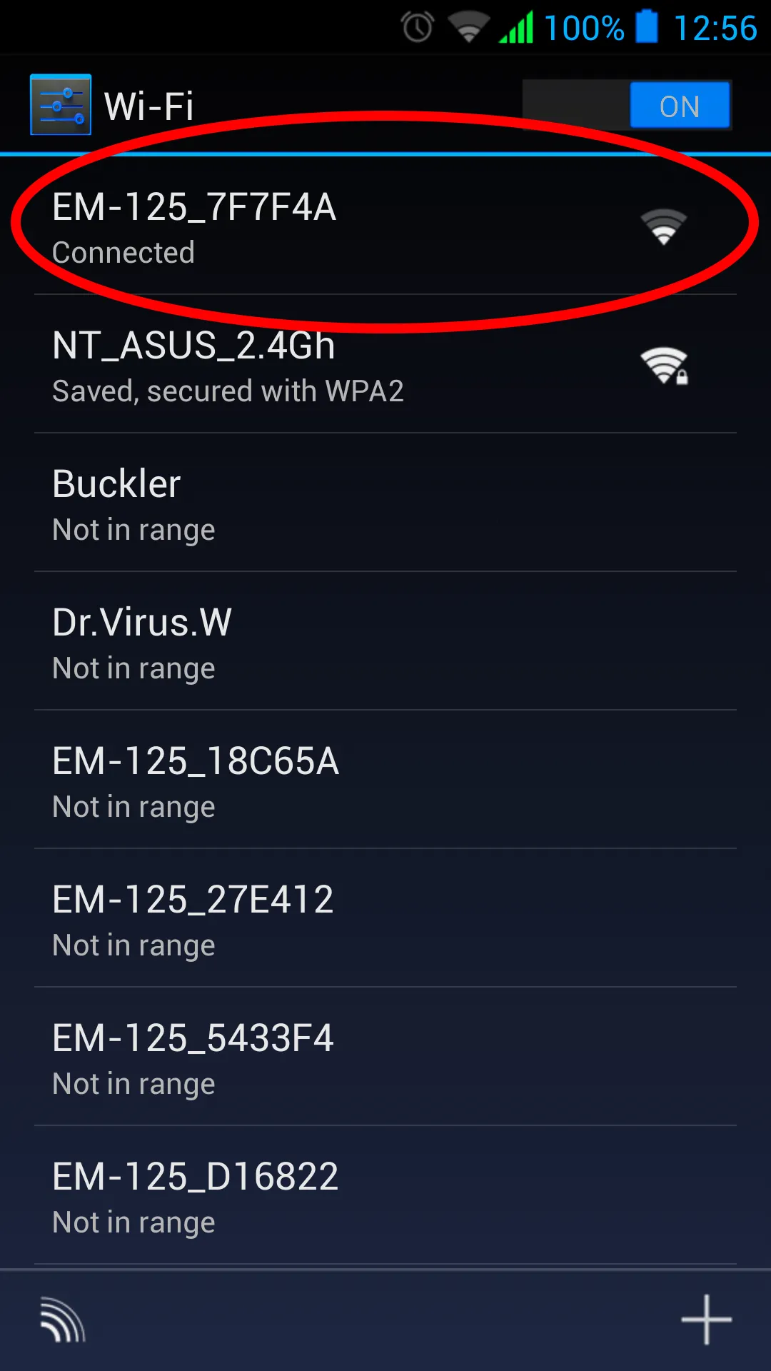
To enter the setup mode, press and hold the “ENTER” button (Fig. 1, pos. 1) on the front panel of the product for 5-6 seconds. The “ENTER” button will start flashing blue-red and EM-125 will create an access point named “EM-125_xxxxxxxx”, where xxxxxxxx is the unique product code (see Fig. 2).
Using an electronic device (PC with Wi-Fi, phone, tablet, laptop, etc.), connect to the access point using the following parameters:
- Access point name: “EM-125_xxxxxxxx”
- Security: None
Launch a web browser (Google Chrome, Opera, Firefox, etc.) on the electronic device.
In the browser address bar, enter “http://em.com” or “http://192.168.4.1” and navigate to the entered link.
The EM-125 web interface will be displayed on the electronic device screen.
Follow the on-screen instructions to configure the Wi-Fi connection for EM-125 and complete authorization on the “my.overvis.com” server.
Web Interface Description
Section titled “Web Interface Description”User Authorization
Section titled “User Authorization”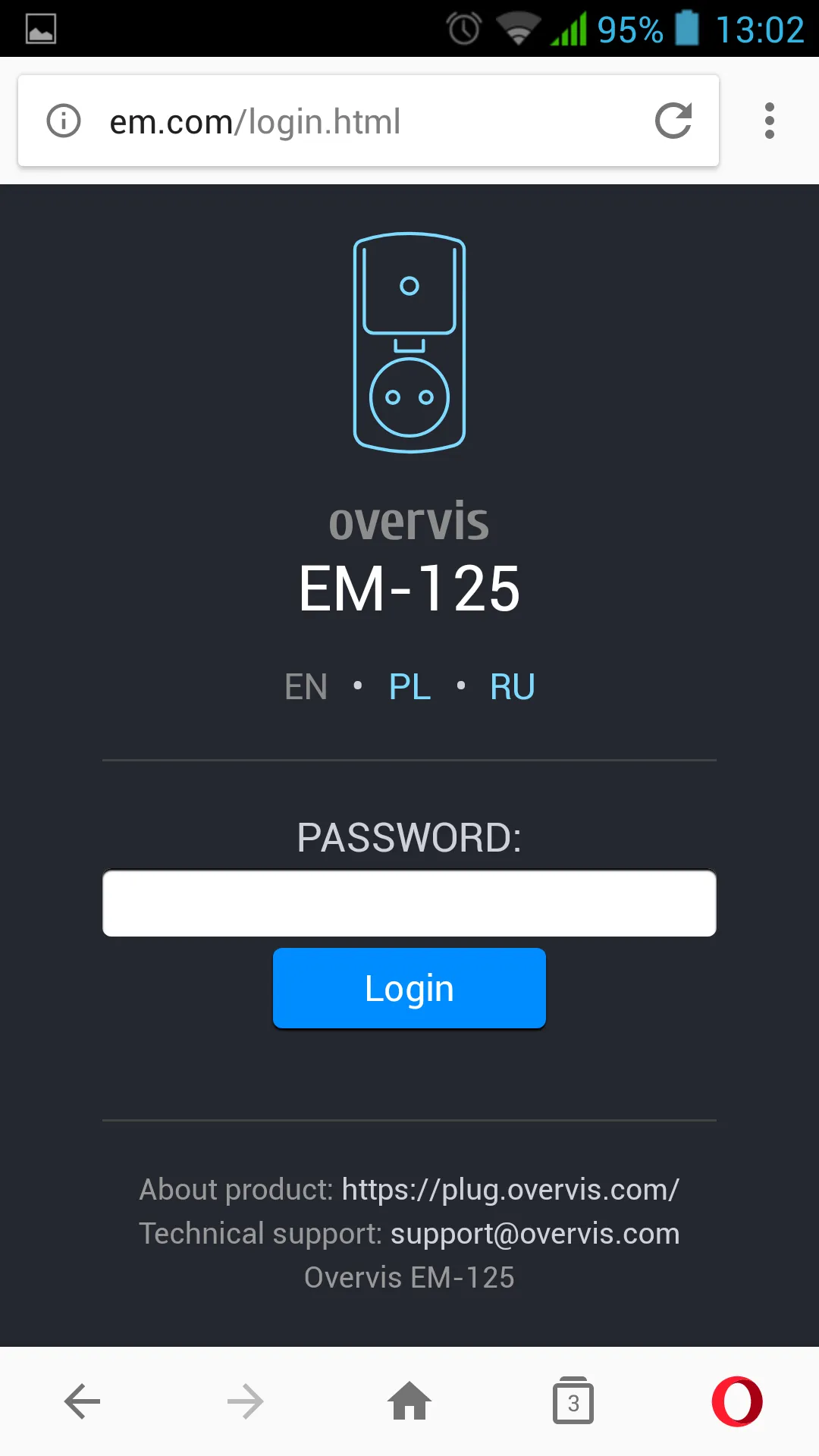
After opening the EM-125 web interface in a PC browser (or any other device with a browser installed), the user authorization page will be displayed.
To access EM-125, you need to enter the login (default “EM-125”) and password (default “admin”).
Status
Section titled “Status”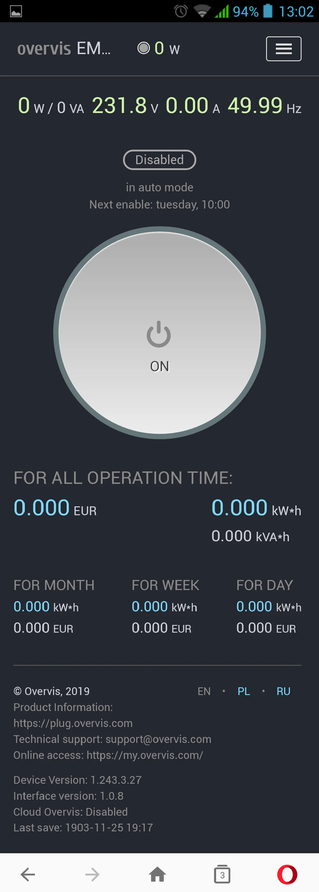
After successful authorization, the status page will be displayed, showing current information about the EM-125 state. All information is read-only.
At the top of the screen, the device name “overvis EM-125”, current power consumption by the load “0 W”, and the ”☰” button for opening the main menu are displayed.
In the middle of the screen, there is a manual control button and readings of measured mains parameters (load current and power, mains voltage and frequency).
At the bottom of the screen, there are counters of consumed electricity and the amount of money spent.
Main Menu
Section titled “Main Menu”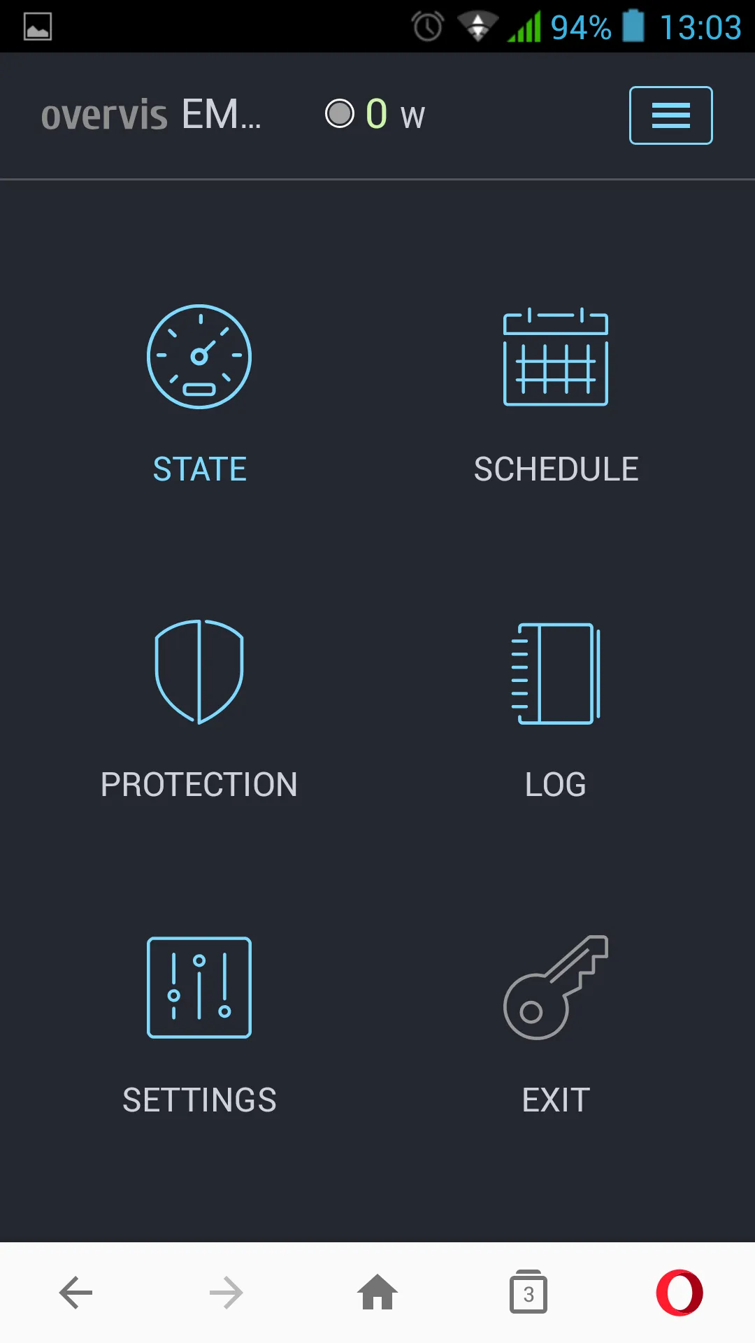
After pressing the ”☰” button, the main menu of the product will be displayed.
To close the menu, press the ”☰” button.
Schedule
Section titled “Schedule”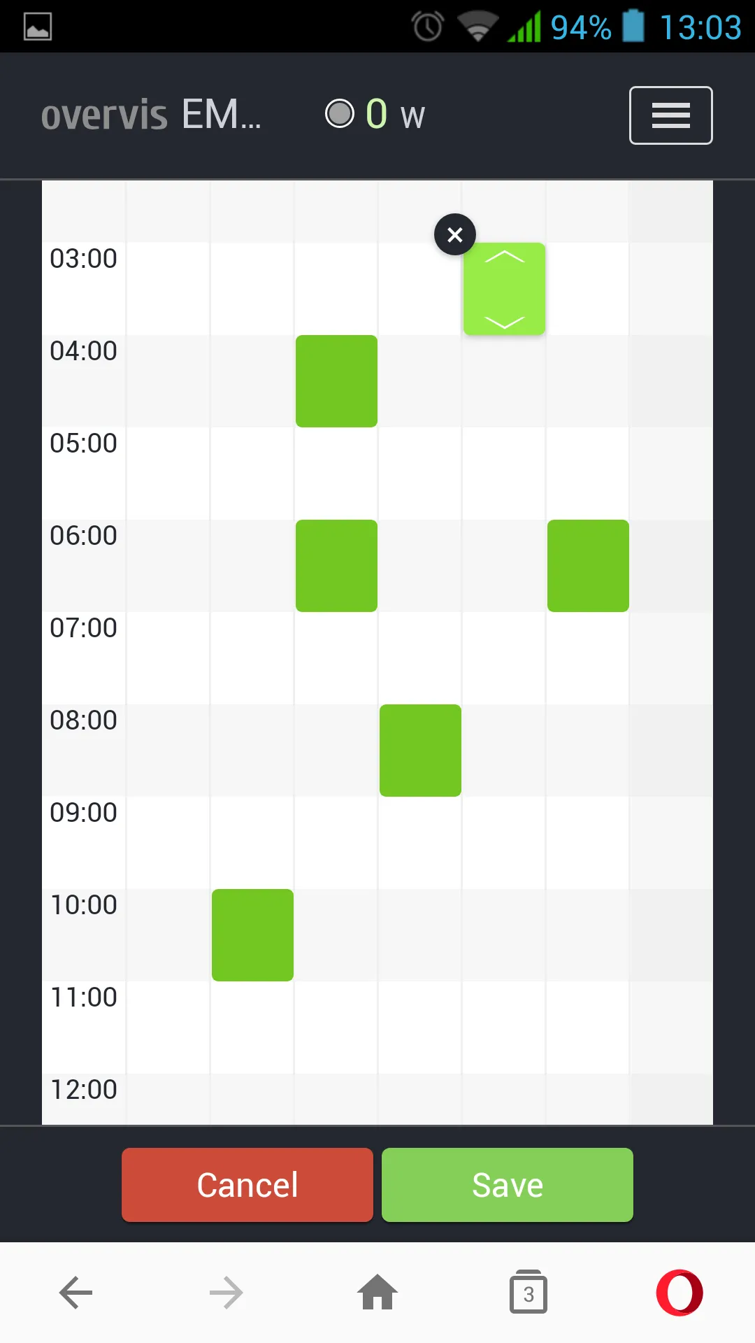
Opens after navigating to the “SCHEDULE” menu item.
Double-clicking on the graph adds an event.
Double-clicking on an event opens the event settings window.
Changing the event time is done by dragging the entire block or using the ”◀” and ”▶” elements.
To delete an event, press ”✕” in the upper left corner of the event.
To save the current schedule to EM-125 — press the “Save” button. To cancel changes — press the “Cancel” button.
Protection
Section titled “Protection”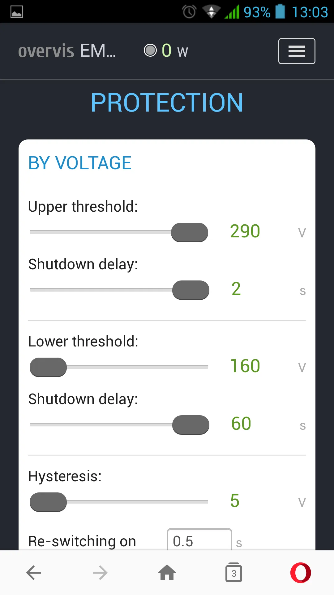
Opens after navigating to the “PROTECTION” menu item.
This menu item contains the protective function settings for EM-125:
- Voltage protection
- Current protection
- Power protection
Voltage Protection:
- Upper threshold — maximum voltage value at which the load will be disconnected
- Disconnect delay — protection response time when the threshold is reached
- Lower threshold — minimum voltage value at which the load will be disconnected
- Hysteresis — voltage hysteresis value
- Reconnection delay — delay before reconnecting the load after an emergency
- Reconnections — number of allowed reconnections after an emergency
- Save — save settings to EM-125
Current Protection:
- Current threshold — protection state at which the load will be disconnected
- Disconnect delay — protection response time when the threshold is reached
- Reconnection delay — delay before reconnecting the load after an emergency
- Reconnections — number of allowed reconnections after an emergency
- Save — save settings to EM-125
Power Protection:
- Protection — protection operation mode (disabled, by active or apparent power)
- Power threshold — power value at which the load will be disconnected
- Disconnect delay — protection response time when the threshold is reached
- Reconnection delay — delay before reconnecting the load after an emergency
- Reconnections — number of allowed reconnections after an emergency
- Save — save settings to EM-125
Settings
Section titled “Settings”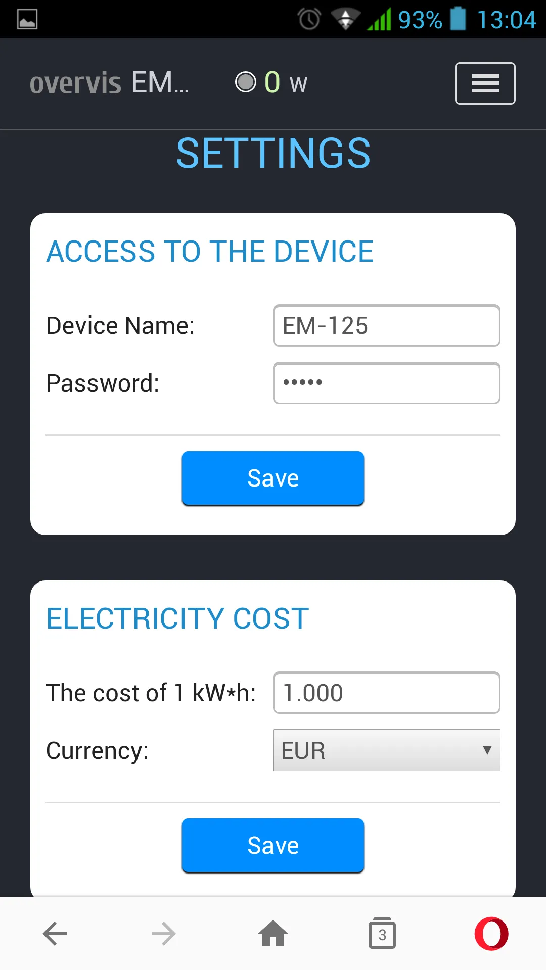
Opens after navigating to the “SETTINGS” menu item.
This menu item contains the main EM-125 settings:
- Device access
- Electricity cost
- Wi-Fi
- Vacation
- Date and time
- Overvis Cloud
- Advanced
Device Access:
- Device name — product name
- Password — sets the access password to EM-125 via Web interface
- Save — save settings to EM-125
Electricity Cost:
- Cost per 1 kWh — sets the electricity cost per 1 kWh
- Currency — sets the currency in which the cost of consumed electricity is calculated
- Save — save settings to EM-125
Wi-Fi:
- Network name (SSID) — name of the network to which EM-125 is connected
- Network password — password of the network to which EM-125 is connected
- TCP/IP settings — TCP/IP configuration mode (manual or automatic DHCP)
- IP address — EM-125 IP address in the Wi-Fi network
- Subnet mask — subnet mask of the network to which EM-125 is connected
- Default gateway — default gateway address in the Wi-Fi network
- Save — save settings to EM-125
Vacation:
- Enable scheduled vacation — vacation planner operation mode (disabled or enabled)
- Start date — vacation planner start date
- End date — vacation planner end date
- Save — save settings to EM-125
Date and Time:
- Device time — current date and time on the device
- Time zone — current time zone on the device
- Enable automatic daylight saving time switch — parameter that allows or prohibits EM-125 from automatically switching to/from daylight saving time
- Time correction — clock correction on EM-125, specified in seconds per day
- Enable time synchronization — parameter that allows or prohibits the product from synchronizing time with an NTP time server
- NTP server address — NTP time server address
- Port — NTP time server connection port
- Synchronization period — period at which EM-125 will synchronize with the NTP time server
- Save — save settings to EM-125
- Synchronize with server — force time synchronization between the NTP time server and EM-125
- Synchronize with PC — start time synchronization between PC and EM-125
Overvis Cloud:
- Enable remote access via cloud — allow or prohibit EM-125 connection to Overvis cloud
- Server address — sets the Overvis cloud address
- Port — connection port
- Status — service information about the Overvis cloud connection status
- Save — save settings to EM-125
Advanced:
- Front panel lock after — time after which the front panel will be locked after power is applied to EM-125 (child protection)
- Device lock after — time after which load activation will be blocked for all operating modes
- Reconnection counter reset time — time after which the allowed reconnection counters will be reset from the moment the emergency disappears
- Indication brightness — sets the brightness of the EM-125 control button backlight
- Save — save settings to EM-125
Configurable EM-125 Parameters
Section titled “Configurable EM-125 Parameters”| Parameter | Range | Default Value |
|---|---|---|
| Network name (SSID) | 32 ASCII characters | ”NT_CHECK_P1” |
| Network password | 64 ASCII characters | ”12345678” |
| TCP/IP settings | Manual / Automatic | Automatic |
| IP address | 0.0.0.0 – 255.255.255.255 | 192.168.0.2 |
| Subnet mask | 0.0.0.0 – 255.255.255.255 | 255.255.255.0 |
| Default gateway | 0.0.0.0 – 255.255.255.255 | 192.168.0.1 |
Voltage Protection
Section titled “Voltage Protection”| Parameter | Range | Default Value |
|---|---|---|
| Upper threshold, V | 230 – 290 | 255 |
| Upper threshold disconnect delay, s | 0.2 – 2.0 | 0.5 |
| Lower threshold, V | 100 – 220 | 190 |
| Lower threshold disconnect delay, s | 0.2 – 60.0 | 12.0 |
| Hysteresis, V | 0 – 20 | 5 |
| Reconnection delay, s | 0.5 – 600.0 | 5.0 |
| Number of reconnections | No, 1, 2, 3, 5, 7, 10, Always | Always |
Current Protection
Section titled “Current Protection”| Parameter | Range | Default Value |
|---|---|---|
| Current threshold, A | 1.0 – 16.0 | 10.0 |
| Disconnect delay, s | 0.2 – 10.0 | 5.0 |
| Reconnection delay, s | 0.5 – 600.0 | 60.0 |
| Number of reconnections | No, 1, 2, 3, 5, 7, 10, Always | 3 |
Power Protection
Section titled “Power Protection”| Parameter | Range | Default Value |
|---|---|---|
| Protection enabled | Disabled / By active / By apparent | By active |
| Power threshold, W | 100 – 3680 | 2300 |
| Disconnect delay, s | 0.2 – 10.0 | 5.0 |
| Reconnection delay, s | 0.5 – 600.0 | 60.0 |
| Number of reconnections | No, 1, 2, 3, 5, 7, 10, Always | 3 |
Vacation
Section titled “Vacation”| Parameter | Range | Default Value |
|---|---|---|
| Enabled | Disabled / Enabled | Disabled |
| Start date | dd.mm.yyyy | 17.08.2018 |
| End date | dd.mm.yyyy | 17.08.2018 |
Device Access
Section titled “Device Access”| Parameter | Range | Default Value |
|---|---|---|
| Device name | 32 ASCII characters | ”EM-125” |
| Web access password | 32 ASCII characters | ”admin” |
Electricity Cost
Section titled “Electricity Cost”| Parameter | Range | Default Value |
|---|---|---|
| Electricity cost | 0.001 – 999.999 | 1.000 |
| Currency | BYR, BGN, CZK, CHF, EUR, GBP, INR, KZT, LVL, LTL, MDL, PLN, PRB, RUB, RON, SEK, UAH, USD | EUR |
Date and Time
Section titled “Date and Time”| Parameter | Range | Default Value |
|---|---|---|
| Time zone (GMT) | GMT-12:00 – GMT+13:00 | GMT+0:00 |
| Time correction, s | -9.9 – +9.9 | +0.0 |
| Auto daylight saving | No / Yes | No |
| Time synchronization | Disabled / Enabled | Enabled |
| NTP server address | 32 ASCII characters | ”time.windows.com” |
| Connection port | 1 – 65535 | 123 |
| Synchronization period, s | 3600 – 86400 | 7200 |
my.overvis.com Cloud
Section titled “my.overvis.com Cloud”| Parameter | Range | Default Value |
|---|---|---|
| Enabled | Disabled / Enabled | Enabled |
| Server address | 32 ASCII characters | ”my.overvis.com” |
| Connection port | 1 – 65535 | 20502 |
Advanced
Section titled “Advanced”| Parameter | Range | Default Value |
|---|---|---|
| Device lock after, s | No, 60 – 43200 | No |
| Button lock | No, 60 – 600 | No |
| Reconnection counter reset time, s | 60 – 3600 | 60 |
| Indication brightness | 1 – 15 | 12 |
Remote Configuration and Control via “my.overvis.com” Server
Section titled “Remote Configuration and Control via “my.overvis.com” Server”Configuration and control via the “my.overvis.com” server is only possible after configuring the Wi-Fi connection and completing authorization on the “my.overvis.com” server (see “Wi-Fi Connection Setup”).
On an electronic device (PC, laptop, mobile phone, tablet, etc.), enter the link “http://my.overvis.com/smartplug” in the web browser address bar (Google Chrome, Opera, Firefox, etc.) and navigate to it.
The device screen will display connection options for EM-125. Select the most appropriate option and follow the further instructions displayed on the screen.
After connecting to EM-125, configure the necessary parameters by following the on-screen instructions.
To disconnect from EM-125 — simply close the “my.overvis.com” page.
7 Product Operation Description
Section titled “7 Product Operation Description”The product operation description uses the manufacturer’s default settings.
Normal Product Operation
Section titled “Normal Product Operation”After connecting EM-125 to a mains socket, there is a 5-second delay, then, if the mains voltage is within acceptable limits, the product starts turning the load on/off according to the user-defined schedule.
After turning on the load, EM-125 constantly monitors the mains voltage, current, and power consumed by the load. If any of them exceeds the set thresholds, EM-125 performs emergency load disconnection.
Also, after plugging EM-125 into a mains socket, it connects to the user-designated Wi-Fi network (for time synchronization and access to the “my.overvis.com” server).
Every 5 minutes, EM-125 saves statistics (voltage, current, power values, etc.) to non-volatile memory for subsequent transmission to the “my.overvis.com” server.
After receiving a manual control command (from the front panel or the “my.overvis.com” server), the execution of the current scheduled event is blocked, the load is turned off (or on, depending on the command), and EM-125 switches to manual control mode.
After the next scheduled event occurs, manual control is disabled and EM-125 returns to normal operation mode.
Every 1-2 hours (depending on the “my.overvis.com” server load), accumulated statistics are sent to the “my.overvis.com” server.
Load Protection by Mains Voltage
Section titled “Load Protection by Mains Voltage”During operation, EM-125 constantly measures the mains voltage.
In case of a sharp voltage increase above 300±10 V, load disconnection occurs with a minimum delay of 0.02 s (fixed time).
In case of a gradual voltage increase above the 255 V threshold (upper disconnect threshold), the load will be disconnected after 0.5 s (upper threshold disconnect delay).
After disconnecting the load, if the mains voltage drops below 250 V (“Upper disconnect threshold” minus “Hysteresis”), return to normal operation mode will occur after the AR time.
In case of voltage drop below the 190 V threshold (lower disconnect threshold), the load will be disconnected after 12.0 seconds (lower threshold disconnect delay).
After disconnecting the load, if the mains voltage rises above 195 V (“Lower disconnect threshold” plus “Hysteresis”), return to normal operation mode will occur after the AR time.
Product operation in emergency mode is described in the “Load Disconnection Due to Emergency” section.
Load Protection by Consumption Current
Section titled “Load Protection by Consumption Current”During operation, EM-125 constantly measures the current consumed by the load.
In case of load current increase above the 10 A threshold (disconnect threshold), the load will be disconnected after 5.0 seconds (disconnect delay).
After disconnecting the load, return to normal operation mode will occur after the AR time.
Product operation in emergency mode is described in the “Load Disconnection Due to Emergency” section.
Load Protection by Consumption Power
Section titled “Load Protection by Consumption Power”During operation, EM-125 constantly measures the power consumed by the load.
In case of load power increase above the 2300 W threshold (disconnect threshold), the load will be disconnected after 5.0 seconds (disconnect delay).
After disconnecting the load, return to normal operation mode will occur after the AR time.
Product operation in emergency mode is described in the “Load Disconnection Due to Emergency” section.
Load Disconnection Due to Emergency
Section titled “Load Disconnection Due to Emergency”In case of an emergency situation (voltage, current, power exceeding values, etc.), the load is disconnected, the AR time countdown begins, and the “ENTER” button starts glowing red.
After the emergency situation disappears, the “ENTER” button starts flashing red with a 0.5 s period, indicating that the AR time countdown is in progress, after which the load will be automatically turned on.
If the AR time countdown ended before the emergency situation disappeared, then the load will be turned on without delay after the emergency situation disappears.
If the number of automatic reconnection attempts has been exceeded (for current and power protection — “3”, for voltage protection — “no”), the product will block load activation and the “ENTER” button will glow red continuously.
To restore product operation, disconnect it from the mains socket, wait 5 seconds, and plug it back in.
Load Control from Front Panel
Section titled “Load Control from Front Panel”A single press of the “ENTER” button lasting 2-4 seconds switches the product to manual load control mode, where each button press turns on (if it was off) or turns off (if it was on) the load.
Factory Reset
Section titled “Factory Reset”To reset to factory settings:
- Unplug the product from the mains socket
- Disconnect the load from the product socket
- Press and hold the “ENTER” button on the product front panel
- Plug the product into the mains socket and continue holding the button for 3 seconds. The “ENTER” button will start flashing blue-red rapidly, release the “ENTER” button
After the factory reset is complete, the “ENTER” button will stop flashing, and the product will automatically restart.
Settings are reset to factory defaults and the product is ready for use.
Data Exchange Protocol Between EM-125 and “my.overvis.com” Server
Section titled “Data Exchange Protocol Between EM-125 and “my.overvis.com” Server”The data exchange protocol between EM-125 and the “my.overvis.com” server is a closed protocol and is not disclosed for security reasons.
All data is received and sent in encrypted form using 256-bit encryption.
8 Operating Conditions
Section titled “8 Operating Conditions”The product is designed for operation under the following conditions:
- Ambient temperature from -5 to +40 °C
- Atmospheric pressure from 84 to 106.7 kPa
- Relative humidity (at +25 °C) 30 … 80%
9 Safety Measures
Section titled “9 Safety Measures”Do not allow water to get on the internal elements of the product, socket, and plug.
To improve operational characteristics, it is recommended to use the product at a load current not exceeding 10 A.
During operation and maintenance, follow the requirements of: “Rules for Technical Operation of Consumer Electrical Installations”; “Safety Rules for Operation of Consumer Electrical Installations”; “Occupational Safety in Operation of Electrical Installations”.
10 Maintenance
Section titled “10 Maintenance”During maintenance, disconnect the product and devices connected to it from the mains socket.
Recommended maintenance frequency — every six months.
Maintenance procedure:
- Visually check for carbon deposits on the product plug; if found, remove the carbon deposits
- Visually check the housing integrity; if cracks and chips are found, remove the product from service and send it for repair
- If necessary, wipe the product housing with a cloth
11 Transportation and Storage
Section titled “11 Transportation and Storage”The product in the manufacturer’s packaging can be transported and stored at temperatures from -45 to +60 °C and relative humidity not more than 80%. During transportation, the product should be protected from mechanical damage.
12 Service Life and Manufacturer’s Warranty
Section titled “12 Service Life and Manufacturer’s Warranty”Product service life is 10 years. After the service life expires, contact the manufacturer.
Storage period — 3 years.
The warranty period for product operation is 3 years from the date of sale.
During the warranty period of operation (in case of product failure), the manufacturer performs free product repair.
Warranty service is provided at the place of purchase or by the product manufacturer. Post-warranty service of the product is performed by the manufacturer at current rates.
Before sending for repair, the product must be packed in factory or other packaging that prevents mechanical damage.
For all inquiries, contact the manufacturer:
NOVATEK-ELECTRO LTD
59, Mykhaila Boltenka (Adm. Lazareva) St.
Odesa, 65007, Ukraine
tel. +38 (067) 565 37 68
+38 (067) 557 12 49
VN250820