EM-130 Operating Manual
Ta treść nie jest jeszcze dostępna w Twoim języku.
This Operating Manual explains the design, purpose, operating rules, and maintenance procedures for the EM-130 Programmable Astronomical Timer with Wi-Fi.
1. Purpose
Section titled “1. Purpose”The EM-130 programmable astronomical timer (hereinafter referred to as the Timer, EM-130) is a microprocessor device connected to Wi-Fi, which is designed to automate the street lighting switching on (poles, lanterns, etc.), illumination of building facades (adjacent territories, parking lots and other objects), heating devices, pumps, fans, and school bells ringing.
EM-130 provides the ability to configure parameters remotely via the built-in Web-interface (using a phone browser, a tablet, etc.), Modbus TCP or a remote Overvis server.
EM-130 automatically calculates the time of sunrise and sunset based on the entered coordinates and the current time enabling controlling lighting without using external sensors.
EM-130 can be used for load management depending on real-time without the need for continuous maintenance.
EM-130 is equipped with its own Wi-Fi access point, which enables direct connecting to the Timer using a mobile device with Wi-Fi and a browser.
You will start saving energy and your money by using EM-130 to control your lighting or heating appliances according to a preplanned schedule.
EM-130 features
Section titled “EM-130 features”- Sunrise and sunset load management (astronomical control)
- Automatic load management according to a user-defined schedule
- Real-time clock with a power reserve of at least 10 days (if there is no external power supply), without the use of built-in batteries
- Manual load management via the Web-interface, Modbus TCP or Overvis server
- Weekly working hours
- Status indicator
- One control button
- Three main modes of Wi-Fi operation (network client, access point, or disabled)
- Time synchronization with the user’s device (phone, tablet, etc.) or with the NTP exact time server
- Saving the schedule to a file
- Loading a schedule from a file
- Intuitive Web-interface
- Remote access to the product from the Overvis server from anywhere in the world where there is an Internet connection
- Connecting the product to the SCADA system using the Modbus TCP protocol
- Two switching groups of synchronously operating contacts allowing you to connect a load of up to 6 A per contact group
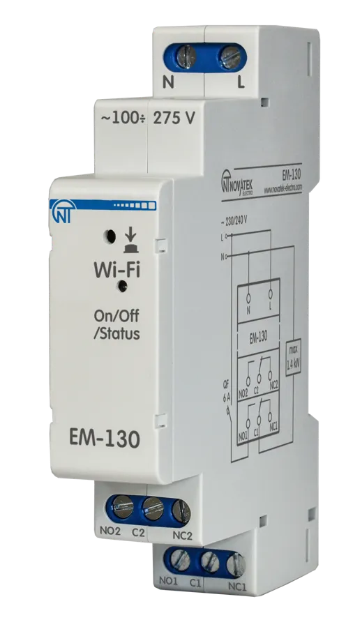
Overall and mounting dimensions and controls
Section titled “Overall and mounting dimensions and controls”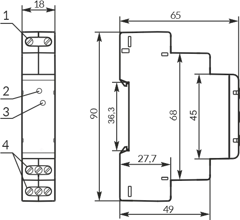
Figure 1 – Overall and mounting dimensions
- Network connection terminals (L and N)
- Control button «Wi-Fi»
- «On/Off/Status» status indicator (hereinafter referred to as the «On/Off»)
- Load connection terminals (switching contact)
Display of «On/Off» indicator states
Section titled “Display of «On/Off» indicator states”| Indicator State | Description |
|---|---|
| Always on | Load is on |
| Blinks slowly (1.0-s period) | The user holds down the «Wi-Fi» button |
| Blinks slowly (0.5-s period) | Connecting to a Wi-Fi access point |
| Fast blinking (period 0.15 s) | Executing a command from the button on the front panel |
| Fast single blink every 5 seconds | The load is disabled and Wi-Fi is disabled |
| Fast double blinking every 5 seconds | The load is disabled, Wi-Fi is in the «network client» mode |
| Fast triple blinking every 5 seconds | The load is disabled, Wi-Fi is in the «access point» mode |
2. Terms and abbreviations
Section titled “2. Terms and abbreviations”| Term | Definition |
|---|---|
| Wi-Fi | A family of standards for transmitting digital data streams over radio channels |
| NTP | Network protocol for synchronizing internal clocks using networks |
| SR | Sunrise (the moment when the upper edge of the solar disk appears above the horizon) |
| SS | Sunset (the moment when the upper edge of the solar disk disappears below the horizon) |
| RT | Real time |
| MON, TUES, WED, THURS, FRI, SAT, SUN | Abbreviated names of days of the week (Monday, Tuesday, etc.) |
| On default | Preset parameter values that the Timer uses in its operation until the user explicitly changes these values |
| Web interface | A system for the user’s interaction with the Timer via the computer browser |
| Browser | Application software designed for requesting, processing, manipulating, and displaying the content of web sites |
3. Technical specifications
Section titled “3. Technical specifications”Table 1 – EM-130 technical specifications
| Parameter | Value |
|---|---|
| Rated power supply voltage | 220 – 240 V |
| Power supply frequency | 45 – 65 Hz |
| Voltage at which operability is maintained | 100 – 275 V |
| Maximum switching load current | 6 A (per contact) |
| Power of the connected load: | |
| AC-1, AC-7a – low inductive load, appliance load | ≤1.44 kW |
| AC-6a, AC-6b – daylight lamps | ≤0.2 kW |
| AC-5b – incandescent lamps | ≤0.5 kW |
| AC-7b – engines, transformers | ≤0.2 kW |
| Readiness time when the power supply voltage is applied | ≤ 2.0 s |
| Real-time clock accuracy ¹ | ±1.5 s/day |
| Real-time clock power reserve ² | ≥ 10 days |
| Time correction possibility | ±20.9 s/day |
| Accuracy of planned events | 1 min. |
| Wi-Fi frequency | 2.412 – 2.484 GHz |
| Wi-Fi Supported standards | IEEE 802.11 b/g/n |
| Wi-Fi encryption protocol | WPA2/PSK |
| Antenna type | In-built |
| Time synchronisation with the NTP server | Available |
| Time synchronisation with the local device | Available |
| Modbus TCP protocol support | Available |
| Support of connection to Overvis server | Available |
| Maximum number of events (schedule) | 1024 |
| Tightening torque of the terminal block screws | 0.4 ±0.1 N·m |
| Timer designation | Control and distribution equipment |
| Rated mode of operation | Lengthy |
| Climatic version | NF 3.1 |
| Timer protection degree | IP20 |
| Switching resource of output contacts – electrical | ≥ 100 000 times |
| Switching resource of output contacts – mechanical | ≥ 1 mln. times |
| Power consumption (under load) | ≤ 1.5 W |
| Permissible degree of contamination | II |
| Overvoltage category | III |
| Class of electric shock protection | II |
| Insulation rated voltage | 450 V |
| Rated pulse withstand voltage | 4.0 kV |
| Weight | ≤ 0.08 kg |
| Overall dimensions, H×B×L | See Fig. 1 |
Installation (mounting): Standard 35 mm DIN rail
The Timer retains its functionality at any position in space.
The Timer meets the requirements of the following: EN 60947-1; EN 60947-6-2; EN 55011; EN 61000-4-2
Harmful substances in an amount exceeding the maximum permissible concentrations are absent.
¹ Provided that synchronisation with the NTP exact time server is enabled and Internet access is available.
² On condition that the Timer has been online for at least 2 hours.
4. Operation conditions
Section titled “4. Operation conditions”The Timer is intended for operation in the following conditions:
- Ambient temperature: from minus 30 to +55 °С
- Atmospheric pressure: from 84 to 106.7 kPa
- Relative humidity (at temperature of +25 °С): 30 … 80 %
5. Principle of operation
Section titled “5. Principle of operation”The Timer’s principle of operation is based on switching the load on/off according to the user’s preset schedule for the entire week (7 days).
A maximum of 1024 events can be set in EM-130 with an accuracy of 1 minute, which the user can distribute over the entire week (7 days) at their discretion.
As a single program event, the user sets:
- The start time of the event (from 00 h : 00 m to 23 h : 59 m) or the time offset relative to sunrise or sunset (±11 h : 59 m)
- Load relay status (enabled or disabled)
Each day, the timer calculates the time of sunrise and sunset and adjusts the time of the event associated with it.
Then, the event time is compared with the internal real-time clock and, if they are equal or the event time is greater than the real time, the Timer will enable/disable the load depending on the state specified in the event.
The above algorithm is performed for each user-defined event. However, if there are more than one events, only the event that is closest to the realtime clock will trigger, and other events will not be executed.
At latitudes where the polar day has occurred, events related to sunset will not be performed, and the time of sunrise is assumed to be 00 h : 00 m.
At latitudes where the polar night has occurred, events related to sunrise will not be performed, and the sunset time is assumed to be 00 h : 00 m.
Astronomical schedule example
Section titled “Astronomical schedule example”Figure 2 shows an example of an astronomical programme where the schedule is set for the whole week – 4 events for each day, for street lighting – 4 hours after sunset and 4 hours before dawn, the rest of the time the lighting is turned off.
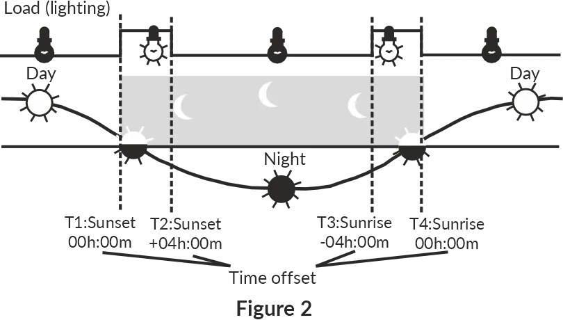
Figure 2 – Astronomical schedule example
Weekly schedule example
Section titled “Weekly schedule example”Figure 3 shows an example of a weekly program, where the schedule is set for the entire week and includes fourteen events to enable and disable the load every day at a certain time.
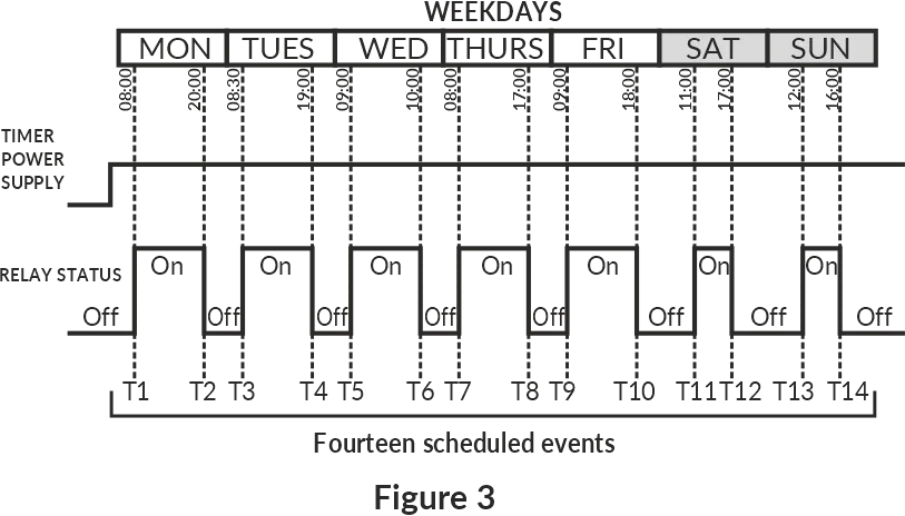
Figure 3 – Weekly schedule example
6. The Timer operation
Section titled “6. The Timer operation”When describing the operation of the Timer, the default settings are used.
After connecting EM-130 to the power supply network, its parameters are initialized for 2 seconds, then the timer begins to turn on/off the load according to the schedule set by the user.
Besides, after EM-130 is connected with the supply network, the timer Wi-Fi switches to the mode set by the user («Wi-Fi access point», «Wi-Fi network client» or «Wi-Fi is OFF»).
Depending on the selected settings, the Web-interface of the timer (on port 80) or the Modbus TCP server (on port 502) is started.
If the timer operates in the «Wi-Fi network client» mode, and there are connections to the «Internet», then:
- Time synchronization with the NTP server is performed every 2 hours (provided that synchronization is enabled in the timer settings)
- A connection is being made to the Overvis server (provided that the connection is enabled in the timer settings) – to provide remote access from the «Internet» to the timer
When a manual control command is received (from the Web interface via the Modbus TCP protocol or the Overvis server), the execution of the currently scheduled event is blocked, the load is turned off (or turned on depending on the command), and the EM-130 switches to manual control mode (disable manual control to return the timer to the scheduled operation mode).
7. Wi-Fi operating modes
Section titled “7. Wi-Fi operating modes”The Timer’s Wi-Fi can operate in four modes (three main and one additional intended for configuration):
- Wi-Fi Access Point Mode
- Wi-Fi network client mode
- Mode without using Wi-Fi
- Wi-Fi connection setup mode
Wi-Fi Access Point Mode
Section titled “Wi-Fi Access Point Mode”EM-130 creates its own access point with the name and password specified by the user during setup.
The user, upon connecting to this access point, and in the browser (Opera, Chrome, Firefox, etc.), after going to «http://192.168.4.1», gets access to the management and settings of EM-130.
Wi-Fi Client Mode
Section titled “Wi-Fi Client Mode”EM-130 automatically connects to the user-defined access point and starts all enabled services (Web-interface, Modbus TCP, and Overvis client).
The management and settings of EM-130 can be accessed via Modbus TCP, the Overvis client, or the Web-interface at the IP address issued to the timer by the router when connecting (for information on how to get the data on the current issued address, please refer to the Operating Instructions for the corresponding router).
If there is no Wi-Fi connection, the EM-130 will automatically try to connect again every 10-15 seconds.
Mode without using Wi-Fi
Section titled “Mode without using Wi-Fi”EM-130 disables Wi-Fi and does not use it for the entire duration of its operation.
To access the Timer’s settings, switch over to the Wi-Fi connection settings mode (see Wi-Fi connection setting up).
Wi-Fi Connection Setup Mode
Section titled “Wi-Fi Connection Setup Mode”EM-130 creates its own access point with the name «EM-130_xxxxxx» (where xxxxxx is the unique Timer’s code) and password «00000000».
The user, upon connecting to this access point, and in the browser (Opera, Chrome, Firefox, etc.) after going to «http://192.168.4.1», gets access to the Timer’s settings.
8. Connecting the Timer
Section titled “8. Connecting the Timer”To ensure the reliability of electrical connections, use flexible (multi-wire) wires with insulation for a voltage of at least 450 V, the ends of which must be stripped of insulation by 5±0.5 mm and compressed with bushing tips. Fixing the wires must prevent mechanical damage, twisting and erasing of the wires’ insulation.
The wire cross-section for connecting a load of 1.44 kW must at least be 1.0 mm².
For reliable contact, tighten the terminal block screws with a force of 0.4 N·m.
Wiring diagram
Section titled “Wiring diagram”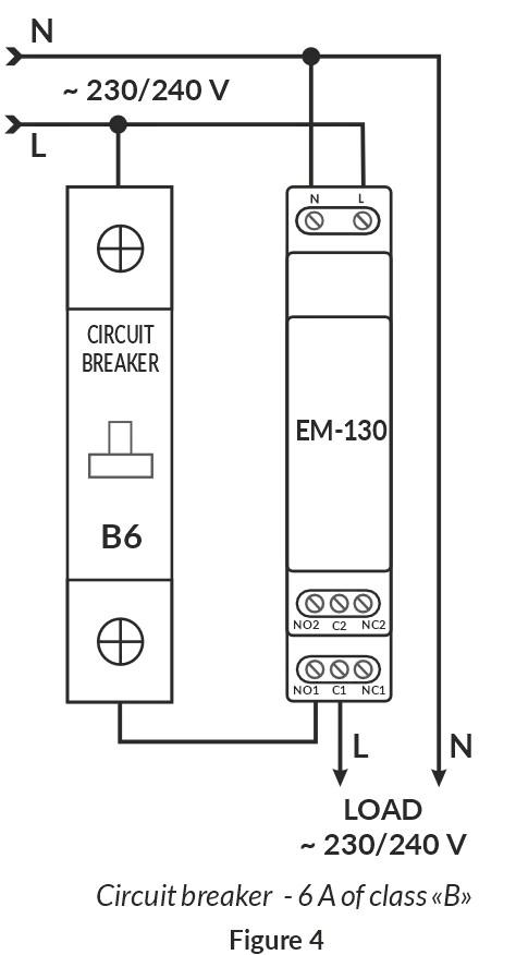
Figure 4 – Wiring diagram
Connection procedure
Section titled “Connection procedure”- Turn off the mains voltage using the circuit breaker.
- Connect the Timer according to the wiring diagram and check that the connection is correct.
- Turn on the circuit breaker.
- Configure the Wi-Fi connection as described in the section Wi-Fi connection setting up.
9. Controlling the «Wi-Fi» button
Section titled “9. Controlling the «Wi-Fi» button”The «Wi-Fi» button (Fig. 1, item 2) is used to control the Timer from the front panel.
When the «Wi-Fi» button is pressed and held, the «On/Off» indicator (Fig. 1, item 3) starts flashing with a period of 1 second helping to count down the time of holding the button.
When the button is released, the command depending on the button holding time starts to be executed, and the «On/Off» indicator starts flashing with a period of 0.15 seconds for 3 seconds.
Table 2 – Wi-Fi button commands
| Holding time | Command |
|---|---|
| 1 – 3 s | Restart the timer |
| 5 – 8 s | Switches the Timer over to the Wi-Fi connection setup mode |
| 10 – 15 s | Reset to factory settings |
| > 15 s | No actions will be carried out |
10. Wi-Fi connection setting up
Section titled “10. Wi-Fi connection setting up”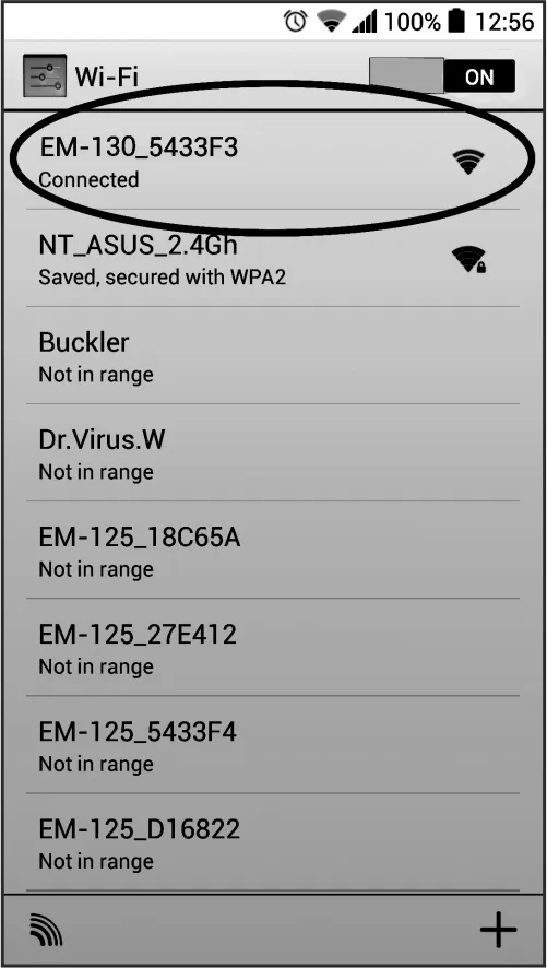
To enter the Wi-Fi connection setup mode, use a thin non-metallic object (for example, a toothpick) and press and hold the «Wi-Fi» button on the front panel of the Timer (Fig. 1, item 2) for 5-8 seconds.
After 5-8 seconds, release the button. In this case, the «On/Off» status indicator will start blinking rapidly (period 0.15 seconds) for 3 seconds.
The Timer will create the access point named «EM-130_xxxxxx», where xxxxxx is the unique Timer’s code (see The Timer’s Main Screen).
Use an electronic device (PC with Wi-Fi, phone, tablet, laptop, etc.) to connect to the access point using the following parameters:
- Access point name «EM-130_хххххх»
- Password «00000000»
Launch the browser (Chrome, Opera, Firefox, etc.) on an electronic device. Enter «http://192.168.4.1» in the browser’s address bar and follow the link you entered.
The screen of the electronic device will display the Web-interface of the Timer and prompt you to enter the password (The Timer password entry screen).
Enter «admin» in the «PASSWORD» field, and click «Login».
After going to the main screen press the «MENU» button.
Then, select «SETTINGS» in the menu.
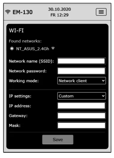
Configure the Timer’s Wi-Fi:
- Network name (SSID) – is the name of the Wi-Fi network
- Network password – is the password for the Wi-Fi network
- Working mode – is the Timer’s Wi-Fi mode
- IP settings – are the settings for the IP address, subnet mask, and gateway address (which are automatically configured by the DHCP server by default)
- MAC address – is the unique address of the Timer
- IP address – is the current IP address of the Timer
- Channel – the current frequency channel of Wi-Fi operation
To save the settings, click the «Save» button.
When the settings are saved, the screen of the electronic device will display a message about the successful saving of the settings and requesting to restart the Timer.
If necessary, configure the remaining parameters.
Restart the Timer by clicking the «Reboot device» button at the bottom of the page.
If the «Working Mode» was specified as a Wi-Fi client, wait for the EM-130 to connect to the specified Wi-Fi (the status indicator will stop flashing blue frequently).
11. Connecting to the Timer via the local Wi-Fi network
Section titled “11. Connecting to the Timer via the local Wi-Fi network”Control and configuration via a local Wi-Fi network is only possible after preconfiguring the Wi-Fi connection (see Wi-Fi connection setting up) and enabling remote access via the Web-interface in the product settings.
In the router settings, you must reserve the IP address of the product by its MAC address (see the Operating Instructions for the router). Or when setting up a Wi-Fi connection, you need to set the «Custom» in the «IP Settings» field and specify static settings:
- IP address – is an unoccupied address in your network (for example: 192.168.0.105 or 10.0.0.5)
- Subnet mask – is your subnet mask (example: 255.255.255.0 or 255.0.0.0)
- Main gateway – is your router’s IP address (example: 192.168.0.1 or 10.0.0.1)
- DNS1 – is the primary name server (example: 208.67.222.222)
- DNS2 – is the secondary name server (example: 8.8.8.8)
Enter the link «http://192.168.0.105» in the address bar of the browser (Chrome, Opera, Firefox, etc.) of the electronic device (PC, laptop, mobile phone, tablet, etc.) and follow it (where 192.168.0.105 is a specified static IP address of the Timer, which may be reserved on the router).
When the password entry page will be displayed (The Timer password entry screen) on the screen of the timer, from which the transition was performed, enter the password («admin», by default) and click «Login».
The Timer password entry screen
Section titled “The Timer password entry screen”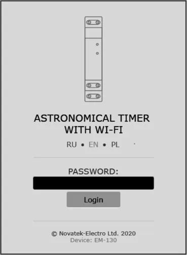
When you log in to the Timer’s Web-interface, you must enter its password.
To do this, enter the password value in the «PASSWORD» field (by default, «admin») and click the «Login» button.
If the entered password is correct, the «PASSWORD» field will be highlighted in green and the user will see the main screen of the web interface.
If the entered password is incorrect, the «PASSWORD» field will be highlighted in red.
The Timer’s Main Screen
Section titled “The Timer’s Main Screen”The main screen provides full control over the Timer and the access to all its functions.
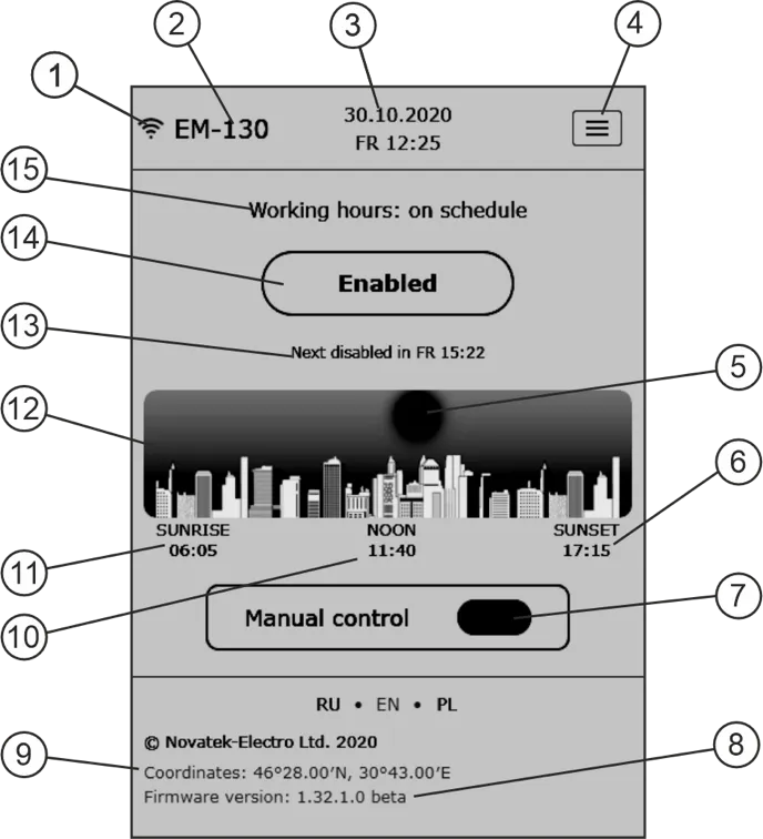
- Wi-Fi signal strength
- Timer’s name «EM-130»
- Time on the Timer
- Menu button
- The «sun» in the daytime and the «moon» at night
- The time of sunset
- Manual control button
- Software version
- Coordinates of the Timer specified by the user
- Time of noon occurrence
- Time of sunrise
- Approximate position of the sun relative to the horizon
- Information about the next event
- The current state of the load and the button of manual enabling/disabling the load
- The current operating mode and information about errors in the Timer operation
The Timer’s Menu Screen
Section titled “The Timer’s Menu Screen”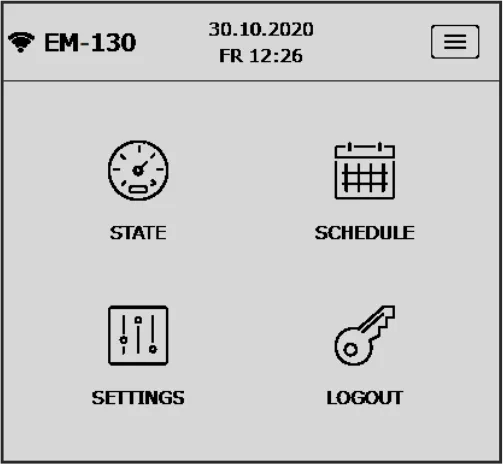
The Timer’s menu screen enables access to various settings of the Timer.
- State – transition to the main screen
- Schedule – viewing and configuring the current schedule
- Settings – the timer’s parameters settings
- Logout – exit from Web-interface
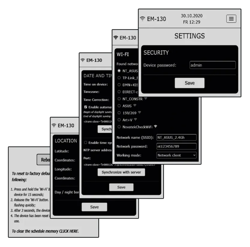
The Settings Screen of the Timer
Section titled “The Settings Screen of the Timer”The settings screen is divided into groups, where each group is responsible for its own set of parameters.
- Security – setting the Timer password
- WI-FI – the Timer’s Wi-Fi connection settings
- Date and Time – settings for date and time, time zone, time correction, and time synchronisation
- Location – settings of coordinates («latitude» and «longitude») of the Timer location (used in calculations of the sunrise and sunset)
At the bottom of the page there are the Timer reset button, the factory reset button and the schedule memory-clearing button.
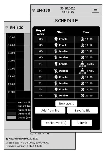
The Timer’s Schedule Screen
Section titled “The Timer’s Schedule Screen”The schedule screen is divided into two parts and enables the creation, editing and viewing the current schedule of the Timer.
In the upper part there is a tabular list of all events and the event management buttons:
- New event – adding a new event
- Add from file – adding the previously saved event list from the file to the current list
- Save to file – saving the current event list in the file
- Delete event – selective events deletion
- Refresh – refreshing the current event list from the Timer
There is the weekly schedule for enabling the load in the lower part of the page.
12. Connecting to the EM-130 via Modbus TCP
Section titled “12. Connecting to the EM-130 via Modbus TCP”Control and configuration via Modbus TCP is only possible after preconfiguration Wi-Fi connections (see Wi-Fi connection setting up) and enabling the remote access via Modbus TCP in the Timer settings.
The Modbus TCP communication protocol allows you to connect EM-130 to the network organized according to the Ethernet standard. Using EM-130 in the network allows you to perform the following functions:
- Data collection in SCADA systems
- Programming EM-130 via a PC (using specialized programs that work with the Modbus TCP protocol)
- Remote control of EM-130 within the local network
When connecting to EM-130, access to the command register and the write-in function is blocked (the read function is not blocked). To unlock the register of command and the write-in function, insert the access code in ASCII characters (default value: «admin») in registers 101 – 164. Write zero values (0000h) in unused registers.
If the access code value is correct, EM-130 will unlock access to the register of command and the write-in function.
The EM-130 is controlled via the command register (see Appendix A. Addresses of registers for Modbus TCP protocol).
After changing the settings is completed, write the value 51930 in the Command Register (a record for the non-volatile (flash) memory). For the changes to take effect, write the value 17513 to the command register (EM-130 restart).
If the write-in functions or access to the command register are not used for a long period of time, block access to them by writing a value other than the access code (for example, 0000h) in registers 101 – 164.
If there is no data exchange within 60 seconds, EM-130 automatically breaks the connection with the client.
Data format for values with decimal point
Section titled “Data format for values with decimal point”In EM-130, all values with a dot are represented as integers. Therefore, additional mathematical operations must be applied when processing the data.
Before writing a value with a dot to EM-130 (for example: 1.000), convert it to an integer by multiplying the value by a factor (1000), and then the result may be written to EM-130.
On a request to read the value with a dot (for example: 1.000), EM-130 returns an integer (1000). To convert the integer to the correct form, divide this number by the conversion factor (1000).
The conversion factor to an integer is determined by the number of decimal places (1.0 – 10; 1.00 – 100; 1.000 – 1000).
Supported Modbus functions
Section titled “Supported Modbus functions”- 03h – Read one or more registers (maximum 125)
- 06h – Single register entry
- 10h – Record of one or more registers (maximum 123)
13. Connecting to the EM-130 via the Overvis server
Section titled “13. Connecting to the EM-130 via the Overvis server”Overvis is a system for monitoring, visualization and remote control of technological processes.
Overvis allows you to:
- Perform round-the-clock periodic data reading
- Save data automatically to your own database
- View data in a convenient form
- Receive alerts about accidents in the form of SMS or E-Mail
Information that is more detailed can be found on the official website www.overvis.com.
The Overvis system acts as a server for collecting data from EM-130 and other devices connected simultaneously, and provides real-time data access only with the permission of the EM-130 owner.
The Manufacturer’s settings of EM-130 are prepared for connecting to the Overvis server, while the Overvis client themselves are disabled in EM-130 and must be activated manually by the User.
To connect EM-130 to the Overvis server
Section titled “To connect EM-130 to the Overvis server”- Connect EM-130 to a Wi-Fi network with the available «Internet»
- Enable the Overvis client in the remote access settings
- In the remote access settings, make sure that the connection to the server is established and the activation code is received
Option 1:
- Scan the QR code (pasted on the side of EM-130) and click on the received link
- Create or log in to your account
Option 2:
- Go to the site «https://overvis.com»
- Create or log in to your account
- Add a new network by filling in the required fields:
- Name – the name of the network being created (for example, EM-130 network)
- Modbus TCP Device – Novatek-Electro EM-130
- Connection type – reverse connection with activation code
- Activation code – specify the activation code from the EM-130 settings
- Password for requesting changes to the device parameters in the network – specify the device password from the EM-130 settings
- Add a new device by filling in the required fields:
- Name – the product name (for example, EM-130)
- Modbus ID – 1
- Initiate from template – Novatek-Electro EM-130
14. Connecting to the Timer in the Wi-Fi Access Point mode
Section titled “14. Connecting to the Timer in the Wi-Fi Access Point mode”Connect to a Wi-Fi hotspot with the help of an electronic device (PC with Wi-Fi, phone, tablet, laptop, etc.) using the Wi-Fi name and password earlier specified by the user when configuring the Timer (see Wi-Fi connection setting up).
Enter the link «http://192.168.4.1» in the electronic device browser address bar (Chrome, Opera, Firefox, etc.) and navigate through it.
When the password entry page will appear on the screen of the timer, from which the transition was made enter the password («admin», by default) and click «Login».
15. Connecting to the Timer in the none-Wi-Fi mode
Section titled “15. Connecting to the Timer in the none-Wi-Fi mode”You cannot connect to the Timer in the none-Wi-Fi mode.
To restore connection to the Timer, configure Wi-Fi according to the section Wi-Fi connection setting up.
16. Real-time clock correction
Section titled “16. Real-time clock correction”Correction of the real-time clock enables compensating for the time lost by the real-time clock due to the influence of external factors on the Timer (such as temperature, humidity, etc.) within one day, from minus 20.9 s to +20.9 seconds.
Correction of the clock is performed in the group of parameters «Date and Time».
Example: If the clock is 4.2 seconds slow per day, you must specify a correction value of +4.2 seconds, and if the clock is 4.2 seconds fast, you must specify a correction value of minus 4.2 seconds.
17. Reboot the Timer
Section titled “17. Reboot the Timer”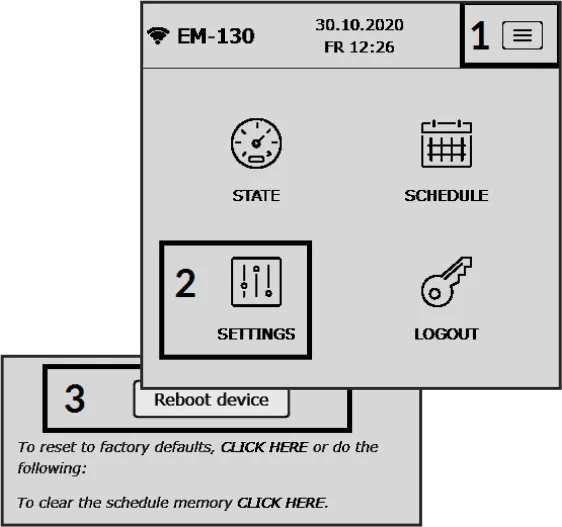
Using a thin non-metallic object (such as a toothpick), press and hold the «Wi-Fi» button for 1-3 seconds on the front panel of the Timer. In this case, the «On/Off» indicator will flash rapidly (0.15 s) for 3 seconds, and the Timer will automatically restart.
18. Resetting to factory settings
Section titled “18. Resetting to factory settings”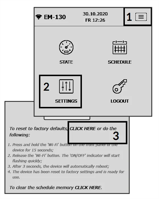
Using a thin non-metallic object (such as a toothpick) press and hold the «Wi-Fi» button for 10-15 seconds on the front panel of the Timer. In this case, the «On/Off» indicator will start flashing every second (helping to count down the time).
Release the «Wi-Fi» button. In this case, the «On/Off» indicator will start flashing rapidly (a period of 0.15 seconds).
When the operation has been completed, the status indicator will stop flashing and the Timer will automatically restart.
The Timer has been reset to factory settings and is ready for use.
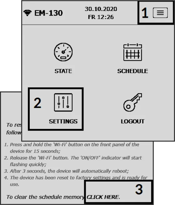
19. Clearing the schedule
Section titled “19. Clearing the schedule”Resetting the schedule is only possible from the Timer’s Web-interface.
Go to the Timer’s settings and click the «CLICK HERE» link as shown in the picture.
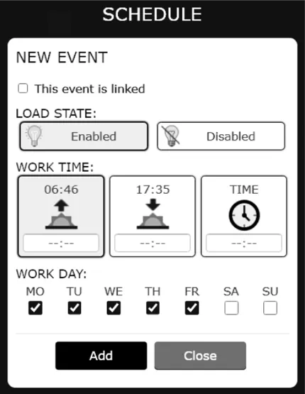
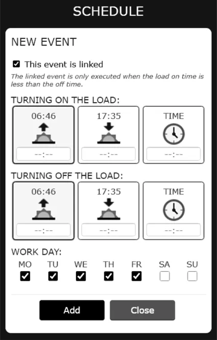
Creating a Schedule
Section titled “Creating a Schedule”On the main screen of the Web-interface, click the menu button. Then, in the menu select «SCHEDULE».
On the schedule screen, click the «New event» button, and the screen will display the input field for the new event.
In EM-130, you can create two types of events, normal, or associated:
- Normal event implies one event – enable (or disable) the load at the specified time
- Associated event involves two actions – turn on the load at the specified time, and then turn off the load at the specified time. In this case, the turn-on time should be less than the turn-off time
Switching between a normal event and an associated event is performed by the parameter «This is a related event».
Custom event fields:
- Condition of loading – the action that will be performed by the event (enabling / disabling the load)
- Trigger time – the time when the event is triggered
- Trigger days – the event trigger days
- Load ON – the time when the load of the associated event is turned on
- Load OFF – the time when the load of the associated event is turned off
Press the «Add» button to add an event.
Press the «Close» button to quit the event-adding mode.
20. EM-130 configurable parameters (for Web-interface)
Section titled “20. EM-130 configurable parameters (for Web-interface)”Security
Section titled “Security”| Parameter | Range | Value after reset |
|---|---|---|
| The Timer password | 64 symbols ASCII | admin |
| Parameter | Range | Value after reset |
|---|---|---|
| Network name (SSID) | 32 symbols ASCII | EM130_xxxxxx |
| Network password | 64 symbols ASCII | 00000000 |
| Wi-Fi operating mode | Network client / Access point / Disabled | Disabled |
| Settings TCP/IP | Manually / Automatically | Automatically |
| IP address | 0.0.0.0 – 255.255.255.255 | 192.168.0.105 |
| Subnet mask | 0.0.0.0 – 255.255.255.255 | 255.255.255.0 |
| Default gateway | 0.0.0.0 – 255.255.255.255 | 192.168.0.1 |
| DNS1 | 0.0.0.0 – 255.255.255.255 | 208.67.222.222 |
| DNS2 | 0.0.0.0 – 255.255.255.255 | 8.8.8.8 |
| MAC-address | Unique MAC-Address of the Timer | — |
| IP-address | Current IP-Address of the Timer | — |
Date and Time
Section titled “Date and Time”| Parameter | Range | Value after reset |
|---|---|---|
| Greenwich time zone (GMT) | UTC-12:00 – UTC+13:00 | UTC+2:00 |
| Time correction, s | -20.9 – +20.9 | +0.0 |
| Automatic changing to summer time and back | No / Yes | No |
| Time synchronisation | Disabled / Enabled | Enabled |
| NTP server address | 32 symbols ASCII | time.windows.com |
| Connecting port | 1 – 65535 | 123 |
Location
Section titled “Location”| Parameter | Range | Value after reset |
|---|---|---|
| Latitude | Northern (N) / Southern (S) | Northern (N) |
| Coordinates (latitude) | +90° – -90° | +50° 27’ |
| Longitude | Eastern (E) / Western (W) | Eastern (E) |
| Coordinates (longitude) | +180° – -180° | +30° 30’ |
| Day/night borderline | Visible sunset / End of civil twilight / End of nautical twilight / End of astronomical twilight | End of civil twilight |
Remote Control
Section titled “Remote Control”| Parameter | Range | Value after reset |
|---|---|---|
| Web-interface turning on | No / Yes | Yes |
| Port of Web-interface | 1 – 65535 | 80 |
| Modbus TCP turning on | No / Yes | No |
| Port Modbus TCP | 1 – 65535 | 502 |
| Overvis turning on | No / Yes | No |
| Overvis server address | 32 symbols ASCII | modbus.overvis.com |
| Port of connection to Overvis | 1 – 65535 | 20502 |
21. Safety precautions
Section titled “21. Safety precautions”It is not allowed water penetration on terminals and internal elements of the product.
During operation and maintenance the regulatory document requirements must be met, namely:
- Regulations for Operation of Consumer Electrical Installations
- Safety Rules for Operation of Consumer Electrical Installations
- Occupational Safety in Operation of Electrical Installations
22. Maintenance
Section titled “22. Maintenance”Recommended frequency of maintenance is every six months.
Maintenance Procedure:
- Check the connection reliability of the wires, if necessary, clamp
- Visually check the integrity of the housing, in case of detection of cracks and damages take the product out of service and send for repair
- If necessary, wipe the front panel and the housing of the product with cloth
23. Transportation and storage
Section titled “23. Transportation and storage”The product in the original package is permitted to be transported and stored at the temperature from minus 45 to +60 °C and relative humidity of no more than 80%. During transportation of the product, protection from mechanical damages must be ensured.
24. Service life and manufacturer warranty
Section titled “24. Service life and manufacturer warranty”The lifetime of the product is 10 years. Upon expiration of the service life, contact the manufacturer. Shelf life is 3 years.
Warranty period of the product operation is 5 years from the date of sale.
During the warranty period of operation (in the case of failure of the product) the manufacturer is responsible for free repair of the device.
Warranty service is performed at the place of purchase or by the manufacturer of the product.
Post-warranty service of the product is performed by the manufacturer at current rates.
Before sending for repair, the product should be packed in the original or other packing which prevents mechanical damage.
Manufacturer contact information
Section titled “Manufacturer contact information”“Novatek-Electro” Ltd.
59, Mykhailo Boltenko (Admiral Lazarev) str., Odesa, Ukraine, 65007
Tel: +38 (067) 565 37 68; +38 (050) 359 39 11; +38 (063) 301 30 40