Quick Start Guide
Цей контент ще не доступний вашою мовою.
This guide walks you through setting up your Overvis MC251 gateway from wiring to successful connection in about 15 minutes.
The Overvis MC251 is a programmable gateway that bridges RS-485 Modbus devices to modern networks, letting you monitor and control industrial equipment remotely via Ethernet or cellular connections.
What You’ll Need
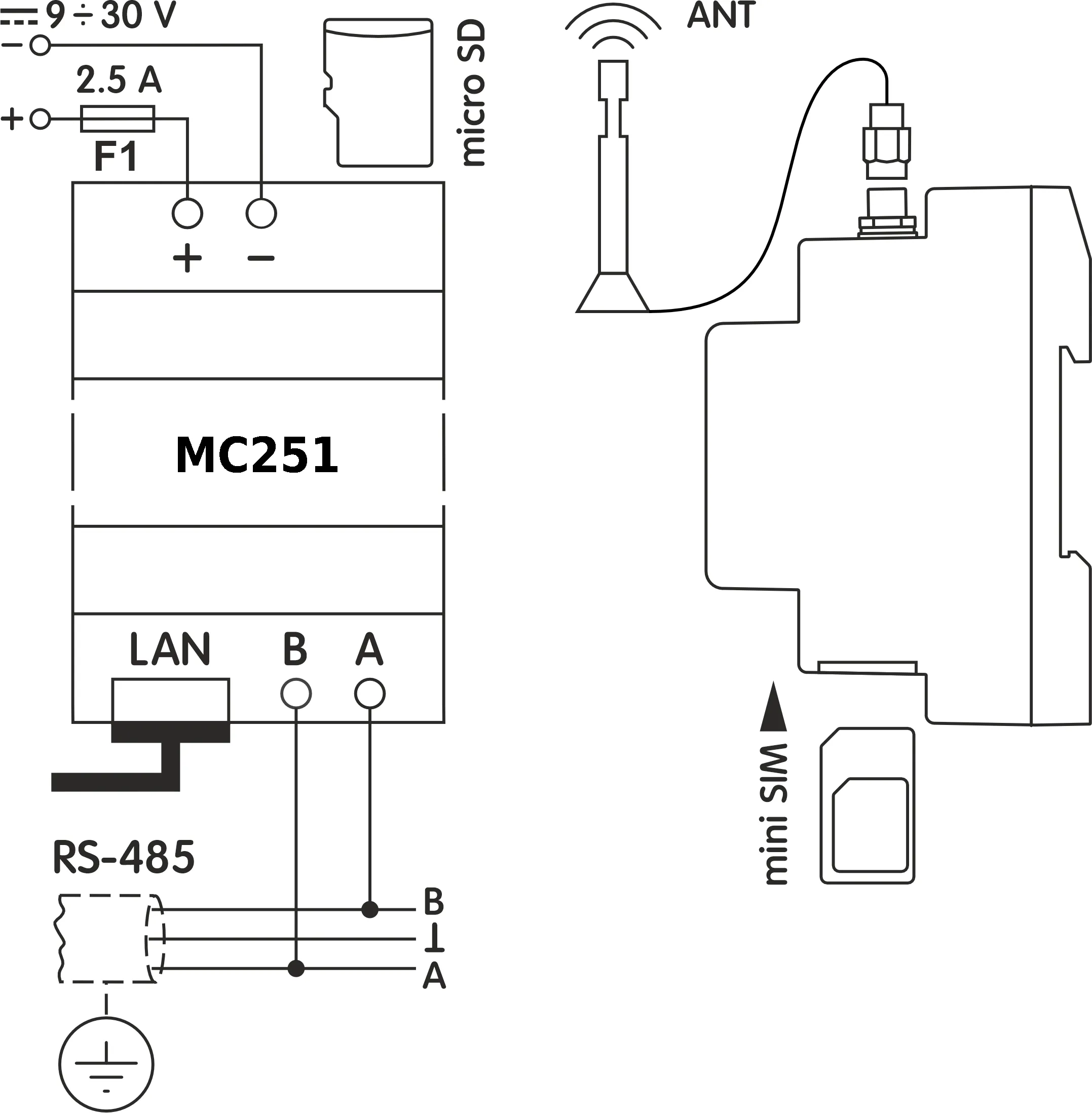
Section titled “What You’ll Need”From the delivery box: MC251 device, Ethernet cable, GSM antenna, 2GB microSD card.
You’ll also need:
- 12V DC power supply (9-30V range supported)
- Device with web browser for initial setup (computer, phone, or tablet)
- RS-485 Modbus devices to connect
- Twisted-pair cable for RS-485 (Category 1+, shielded recommended)
- Stranded wire (≥1 mm² cross-section), ferrules, and tools (screwdriver, wire stripper)
Step 1: Physical Setup
Section titled “Step 1: Physical Setup”Mount your MC251 on a standard 35mm DIN rail in a well-ventilated location. The device operates from -35°C to +55°C, but avoid areas with excessive vibration, humidity, or corrosive atmospheres.
Install memory card: Insert the provided 2GB microSD card into the SD slot. The memory card is required for firmware updates, data logging, and automation logic programming features.
Install SIM card (if using GSM/LTE): If you plan to use cellular connectivity, insert your SIM card (with data service enabled) into the SIM slot now. Attach GSM antenna to the ANT connector.
Network connection: Connect the Ethernet cable from MC251’s LAN port to your router or directly to your computer.
Before making any electrical connections, ensure all devices are powered off.
Tighten terminal screws to 0.4 N·m — enough for solid contact without damage.
RS-485 wiring: Connect twisted-pair cable to MC251’s RS-485 terminals: terminal A for non-inverted signal, terminal B for inverted signal (your devices might label these as A/D+/+ and B/D-/- respectively). Run the cable to your Modbus devices and connect accordingly. Use shielded twisted-pair cable (Category 1 or better) for reliable communication over distance.
Power: Connect 12V DC power to the 9÷30V terminals. For safety, install a 2.5A fuse in the power circuit. Use stranded wire with ferrules, stripped 5mm. Wire cross-section should be 0.5-3 mm².
Step 2: Power On
Section titled “Step 2: Power On”When you apply power, all LEDs light up briefly during the 2-second initialization, then the device spends 10-15 seconds establishing network connections.
The PWR LED stays on to confirm power. The LAN LED turns on when Ethernet connects (blinking during data transfers). The GSM LED blinks slowly (every 1.5s) when registered to cellular network, or rapidly (3 times/second) after TCP/IP link start.
The display shows IP addresses (prefixed with (E) for Ethernet or (G) for GSM), plus data rates and signal strength.
Step 3: Access Web Interface and Configure Internet Connection
Section titled “Step 3: Access Web Interface and Configure Internet Connection”Note the IP address from the display (press R to wake it). If connected via Ethernet with DHCP, you’ll see the assigned address.
Connecting directly to a PC?
Without a DHCP server, the device would use default 192.168.0.111, showing it on the display in a minute after power-up. Configure your computer’s network adapter with IP 192.168.0.10 (or any address from 192.168.0.1-254 except 111), subnet mask 255.255.255.0, leave gateway blank. See the Connections Guide for OS-specific instructions.
Open a web browser and enter the IP address shown on the display (e.g., http://192.168.0.111).
Login to quick setup: You’ll see a login page. Press the R button on MC251 for temporary password-free access.
Configure network: Enable/disable DHCP, set static IP if needed, adjust subnet mask and gateway. For GSM, enter your mobile operator’s APN (Access Point Name) and SIM card PIN (if present).
Step 4: Connect to Overvis Cloud
Section titled “Step 4: Connect to Overvis Cloud”Overvis Cloud provides remote monitoring and control through a web dashboard.
The device label includes a QR code and PIN for quick setup. It is necessary to connect the device to Overvis, which allows to further configure, operate and monitor MC251.
-
Access Overvis server: Scan the QR code on the device label or manually enter the link from the label (format:
https://c.overvis.com/ABCD1234where the last part is your PIN). The link redirects to Overvis server’s login page. -
Login or create account: Enter your credentials if you have an account. New users should create an account first.
-
Create Network: After login, Overvis shows the “Create Network” page. If you came from the QR code/link, the PIN is pre-filled. Otherwise, enter the PIN from the device label and click “Check connection.”
-
Verify connection status: Overvis displays the connection status — either “Connected” or “Device is not connected to the server.” If not connected, check that MC251 has internet access (Ethernet or GSM) and verify the Cloud tab settings in the web interface.
-
Configure your network: Give your network a descriptive name (a “network” represents your MC251 plus all connected Modbus devices). MC251 itself (unit ID
111) is added automatically. -
Add connected devices: Select your RS-485 device models from the dropdown menus and enter their Modbus addresses. Overvis creates device instances from templates matching your selections.
-
Test communication: Open a device page in Overvis and read its parameters to confirm real-time communication is working.
Troubleshooting
Section titled “Troubleshooting”Display shows (E) 0.0.0.0: → Normal during first 20-60 seconds while DHCP negotiates. If it persists, check cable connection and router DHCP. Try direct PC connection with static addressing settings.
Display shows (E) 192.168.0.111: → DHCP failed or is unavailable. MC251 has switched to its factory default static IP address. Either configure your client device to the same subnet (192.168.0.x) or enable DHCP on your router.
Can’t access web interface: → Verify IP address entered in browser matches what’s on the display. Ensure Ethernet address is used (the one marked with (E) in the second line). Check PC and MC251 are on the same subnet. Temporarily disable firewall. Press R for password-free access. Clear browser cache.
GSM won’t connect: → Verify SIM card is fully inserted (until you hear a click), check the antenna is attached, check the GSM settings. Check that data service is active. Check signal strength on display (should be >0%). Try relocating antenna to better position. Try to disable PIN. Try manually configured APN settings.
Cloud server states “Device is not connected” → Check internet connectivity (verify IP addresses on display), check MC251 web page for configuration, status and errors
Cloud server does not accept the device PIN → Verify you entered the exact PIN from this device label
Can’t create cloud account → Ensure email address entered is valid, check email for verification link
No data response from MC251 itself → Check Modbus ID in the cloud device configuration for “MC251” device
MC251 responds but RS-485 devices don’t: → Most common issue is mismatched settings. Select MC251 device (in newly created network) and configure baud rate and parity to match all the devices. Check A/B wiring polarity (swapping these is very common - this doesn’t cause equipment damage, but prevents communication). Try increasing delays in MC251 settings for RS-485. Ensure protocol (Modbus RTU/ASCII) and parity are the same for all the devices. Start with 9600 baud, RTU, AUTO-STOP parity.
Wrong data returned as a response → Check register address matches your device’s documentation. Check the parameter type in the configuration of the cloud device parameter (with this address)
Service Button Quick Reference
Section titled “Service Button Quick Reference”The R button functions depend on press duration:
Quick press: Wake display, show status, grant temporary web access
Hold 2-8 seconds: Prepare for safe memory card removal and restart device
Hold 8+ seconds: Factory reset (erases all settings)
What’s Next?
Section titled “What’s Next?”- MC251 Operating Manual — Complete technical documentation
- Web Interface Guide — Configuration options explained
- Connections Guide — Network setup, VPN, and security
- Modbus Interface — Protocol details and register reference
Need Help?
Section titled “Need Help?”For technical support and assistance:
- Email: support@overvis.com
- Support portal: www.overvis.com/support