Appendix B: Device Adjustment
Цей контент ще не доступний вашою мовою.
1 General Instructions
Section titled “1 General Instructions”Adjustment of instrument must be done by qualifying specialists of metrological service if the measurement errors of input parameters are more than settled value.
Before this operation necessary to check parameter set value Sh1 (Sh2, Sh3, Sh4) - “characteristic shift” and fix it equal to zero.
2 Adjustment of Instrument TR-101
Section titled “2 Adjustment of Instrument TR-101”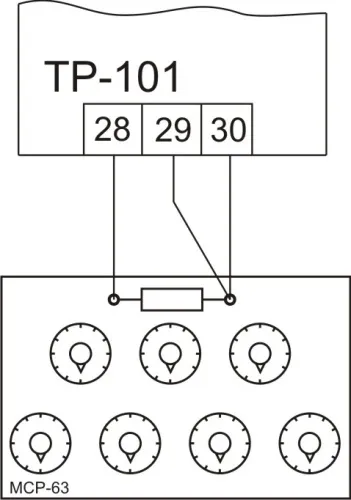
Figure B.1 – TR-101 Adjustment Setup
2.1 Wire Resistance Requirements
Section titled “2.1 Wire Resistance Requirements”Resistance of wires should be equal in a line to each other and everyone should not exceed size 15 Ohm.
2.2 Resistance Box Connection
Section titled “2.2 Resistance Box Connection”Plug into device input resistance box (instead of sensor) with accuracy class at least 0.05 (for example MSR-63) on three wire line (Figure B.1).
Fix at resistance box the following values depending on sensor type:
| Sensor Type | Resistance Value (Ohm) |
|---|---|
| Pt50, Cu50 | R = 50.00 |
| Pt100, Cu100, Ni100 | R = 100.00 |
| Ni120 | R = 120.00 |
| Pt500, Ni500 | R = 500.00 |
| Pt1000, Ni1000 | R = 1000.00 |
| PTC1000 (EKS111) | R = 807.00 |
2.3 Verification Procedure
Section titled “2.3 Verification Procedure”- Power on TR-101
- After 20-30 seconds make adjustment of device
- Be sure that the temperature value for resistance 50, 100, 120, 500, 807, 1000 is equal to 0 °С
- The pink limit of absolute accuracy is ±1 °С
2.4 Characteristic Shift Adjustment
Section titled “2.4 Characteristic Shift Adjustment”Fix parameter value Sh1 (Sh2, Sh3, Sh4) equivalent to temperature deviation but taken with opposite sign.
Test accuracy of settled value: without changing the resistance, wait till the device passes into temperature mode and be sure that its indications are 0±1 °С.