UBZ-304 Operating Manual
Цей контент ще не доступний вашою мовою.
This Operating Manual is intended to familiarize you with the device, the requirements for safety, operation and maintenance procedures of the universal motor protection device UBZ-304 (hereinafter referred to as the device or UBZ).
During operation and maintenance, the regulatory document requirements must be met, namely:
- Regulations for Operation of Consumer Electrical Installations;
- Safety Rules for Operation of Consumer Electrical Installations;
- Occupational Safety when in Operation of Electrical Installations.
Installation, adjustment and maintenance of the device must be performed by qualified personnel having studied this Operating Manual.
In compliance with the requirements of this Operating Manual and regulations the device is safe for use.
The device meets the requirements of the following international standards:
- EN 60947-1
- EN 60947-6-2
- EN 55011
- EN 61000-4-2
Harmful substances in amounts exceeding maximum permissible concentrations are not available.
Abbreviations and terms
Section titled “Abbreviations and terms”| Abbreviation | Meaning |
|---|---|
| ARS | Automatic restarting |
| MS | Magnetic starter |
| PC | Personal computer |
| CT | Current transformer |
| LCD | Liquid crystal display |
| MNS | Minimum number of settings (it is used in phrases as MNS mode or MNS list) |
| Iсt | Rated current of CT (it is set when external CTs using; e.g., if CТ is of Т-0.66 300/5 type, then Iсt equals to 300A) |
| In | Rated current of the motor; As a rule, this value of current is indicated on the motor nameplate, but depending on the operating conditions, the different value of current can be set |
| S.c. | Short circuit |
1. Application
Section titled “1. Application”1.1 General
Section titled “1.1 General”UBZ-304 is designed for protection of induction motors with power of 2.5 to 315 kW in case of using the external standard current transformers with 5A output current.
UBZ can be operated in networks both with insulated and dead grounded neutral.
The device is of DIN rail design version.
UBZ provides continuous monitoring of mains voltage parameters, current values of the phase (line) currents of three-phase electrical equipment for 400/415V, 50Hz, and checking the resistance values of motor insulation.
UBZ provides protection of electrical motors in case of:
- low-quality network voltage (unacceptable power surges, phase failure, incorrect phase sequence and phase “coincidence”, the imbalance of phase/line voltages, the reduction in the network frequency lower than the set one and (or) the increase of network frequency higher than the set value);
- mechanical overloads (symmetrical overload in phase/line currents);
- the threshold crossing of the negative-sequence current;
- unbalance of phase currents without overload associated with the insulation fault inside motor and/or the power cable (the comparison of current unbalance factor according to inverse sequence with voltage unbalance factor according to inverse sequence);
- the torque failure on the motor shaft (“dry running” for pumps) – protection based on the minimum starting and/or operating current;
- motor delayed start or rotor blocking;
- extremely low isolation between the stator and the motor housing (pre-startup check);
- ground fault of the stator winding during operation – ground leakage current protection;
- motor thermal overload;
- overheated windings (temperature of windings is determined using the motor built-in temperature transmitters or the temperature of the housing when using the external temperature transmitters).
For each type of protection, it is possible to have banning and permitting of automatic restarting (hereinafter referred to as ARS) with load.
UBZ provides for electric equipment protection by means of controlling the coil of the magnetic starter (contactor).
UBZ detects motor currents when load relay is off (when the load relay is off and functional relay is in star-delta mode). In this case, UBZ indicates the fault of external contactor starting the motor until UBZ is turned off or control of motor currents is disabled when load relay is off.
UBZ provides for electric motors control:
- using analog inputs “0-20 mA” and “0-10 V”;
- using remote control channels (RS-232 and RS-485 interfaces);
- by buttons on the front panel of UBZ.
Communication
UBZ provides:
- parameters control and transmission by RS-485 interface using MODBUS Protocol,
- parameters control and transmission by RS-232 interface.
For UBZ operation with PC the program of UBZ-304/305 Control Panel can be used; it is available on the website of NOVATEK-ELECTRO Company (https://novatek-electro.com/en/software/control-panel-of-ubz-304305.html).
UBZ-304/305 Control Panel program is designed to monitor the status and collect data of the UBZ-304 device via RS-232 or RS-485 communication interfaces (MODBUS Protocol). The program allows for saving (loading) various UBZ settings, retrieving data and save them for further analysis. Data saved can be viewed in the graphs, comparing the parameters with each other.
Graphic interface of the control panel allows real-time viewing the current status of various UBZ parameters. The flexible adjustment of interface allows adapting to the needs of any user.
1.2 Changes in the Characteristics and Operation of UBZ Depending on Program Version
Section titled “1.2 Changes in the Characteristics and Operation of UBZ Depending on Program Version”If the software version is 5 or less, then changes in UBZ characteristics and operation are not available.
- Version 7: metering of total, active and reactive energies is added.
- Version 8: integrity control of voltages and currents calibration factors is added.
- Version 9: control algorithms by the engine on analog inputs are added.
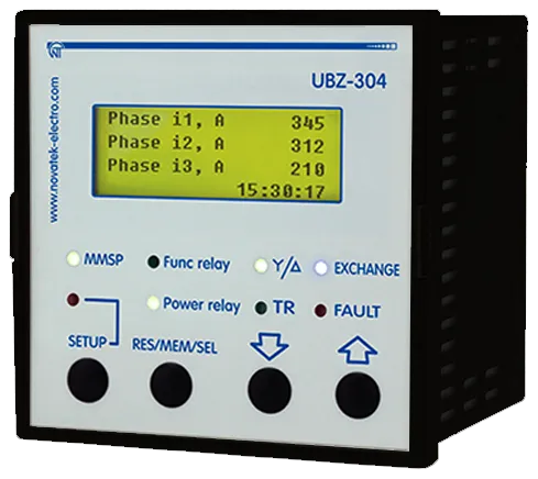
1.3 Controls and Overall Dimensions
Section titled “1.3 Controls and Overall Dimensions”Overall dimensions of UBZ are given in Figure 1.1.
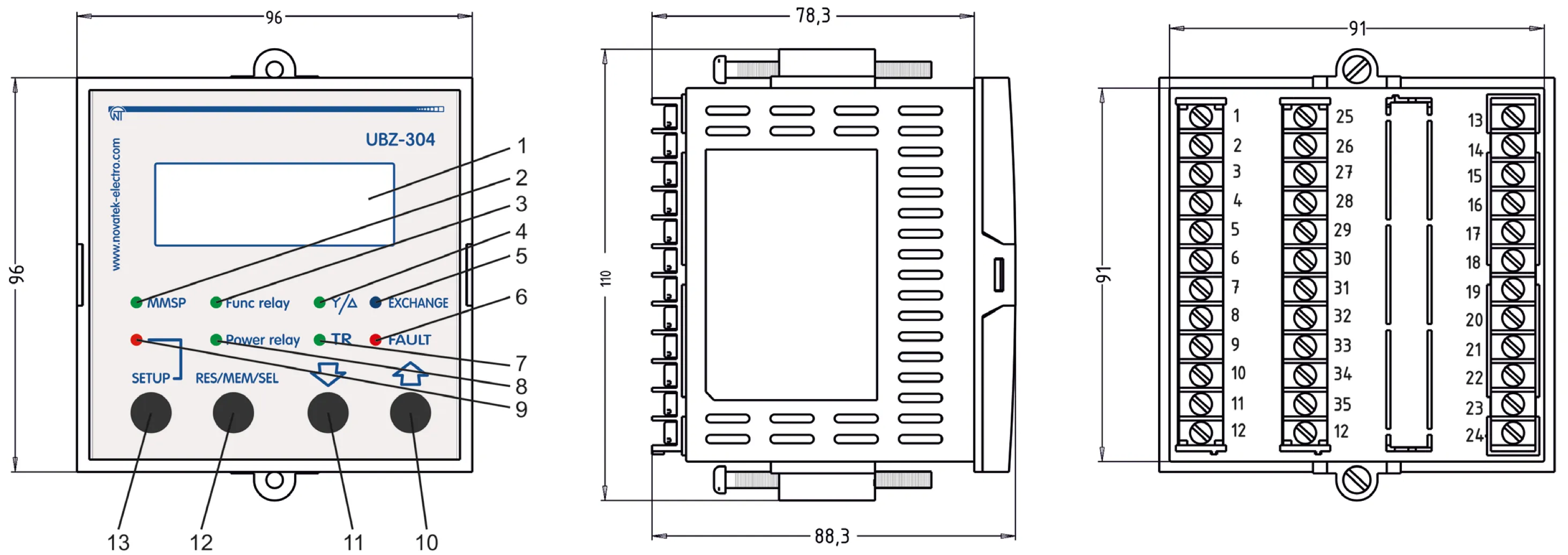
Figure 1.1 – Controls and Overall Dimensions of UBZ
- LCD
- Green LED MMSP is on when the relay is in MNS mode
- Green LED Func relay is on when functional relay is on
- Green LED Y/△ is on when UBZ functional relay operates in star-delta mode
- Blue LED EXCHANGE is on when data exchange with PC occurs
- Red LED FAULT:
- when load relay is off: it is on when UBZ is in fault conditions (it flashes if after fault ARS is expected);
- when load relay is on: it flashes when the motor is in conditions of over-current or thermal overload but relay off time has not come yet
- Green LED TR is on when UBZ functional relay operates in time-delay relay mode
- Green LED Power relay:
- it is on when load relay is on;
- it flashes if UBZ is within hysteresis band when controlling using analog inputs
- Red LED SETUP is on when UBZ is in the mode of parameters setting
- Button ↑ (UP) is scrolling of displayed parameters in the parameter view mode and scrolling of the menu in the parameters setting mode
- Button ↓ (DOWN) is scrolling of displayed parameters in the parameter view mode and scrolling of the menu in the parameters setting mode
- Button RES/MEM/SEL is the parameters recording in the setting mode, switching over the group of displayed parameters in the view mode, reset
- Button SETUP turns on the parameters setting mode
1.4 Operating Conditions
Section titled “1.4 Operating Conditions”UBZ is designed for operation in the following conditions:
- Ambient temperature: from minus 20 to +55°С
- Atmospheric pressure: from 84 to 106.7 kPa
- Relative air humidity (at temperature of +25°С): 30 … 80%
If the temperature of the device after transportation or storage is different from the temperature of the environment in which its operation is assumed, then before connecting to the mains keep the device in operation conditions for two hours (because on the device elements condensation may be available).
2. Components
Section titled “2. Components”Table 2.1 – Delivery Set
| Description | QTY |
|---|---|
| UBZ-304 | 1 |
| Differential transformer (zero sequence transformer) TP-5-45* | 1 |
| Cable for communication with PC via RS-232 (type - КС-01) | 1 |
| Temperature transmitter (types: Pt100, Ni100, Ni120)** | 1 |
| Fasteners | 2 |
| Rubber gasket | 1 |
| Operating manual | 1 |
| Packing | 1 |
* Current transformers, “Novatek-Electro” production: ТР-7-5-100, ТР-7-5-120, ТР-7-5-150 and other, is delivered upon agreement with the Customer.
** Delivered by agreement with the buyer for a separate fee.
3. Specifications
Section titled “3. Specifications”3.1 Basic Technical Specifications
Section titled “3.1 Basic Technical Specifications”Table 3.1 – General Data
| Description | Unit | Value |
|---|---|---|
| Application of the device | – | Switchgear and control-gear; induction motor protection control |
| Design (installation) type | – | DIN rail 35 mm |
| Protection rating of front panel | – | IP64 |
| Protection rating of housing | – | IP10 |
| Climatic version | – | NF 3.1 |
| Contamination level | – | II |
| Overvoltage category | – | II |
| Rated voltage of insulation | V | 450 |
| Rated impulse withstand voltage | kV | 2.5 |
| Electric shock protection class | – | II |
| Wire cross section for connection to terminals | mm² | 0.5 – 2 |
| Torque for terminal screws | N·m | 0.4 |
Table 3.2 – Technical Specifications
| Description | Value |
|---|---|
| Operating supply voltage, three-phase | 400/415 V, 50 Hz |
| Mains frequency, Hz | 48 – 62 |
| Rated current of CT, A | 5 |
| (Phase/line) voltage hysteresis, V | 10/17 |
| Heat hysteresis, in % of accumulated heat in case of shutdown | 33 |
| Determination accuracy of trip threshold for current, not more, in % of rated value | 2 |
| Determination accuracy of trip threshold for voltage, not more, V | 3 |
| Determination accuracy of out-of-phase voltage, not more, V | 3 |
| Voltage when maintaining serviceability: | |
| - phase voltage, when powered by one phase and zero wire is connected, not less, V | 180 |
| - line voltage, when powered by three phases, not more, V | 450 |
| Analog inputs: | |
| - input to connect temperature transmitter (types: Pt100, Ni100, Ni120), pcs. | 1 |
| - input to connect temperature transmitter of PTC-1000 type, pcs. | 1 |
| - three analog inputs for standard CT with 5A output (T-0.66 type or similar), pcs. | 3 |
| - input to connect differential current transformer (zero sequence transformer) pcs. | 1 |
| - input to measure current of 0-20 mA, pcs. | 1 |
| - input to measure voltage of 0–10 V, pcs. | 1 |
| Main outputs: | |
| - load relay – two groups of changeover contacts to control the electric motor starter – 8 A, 250 V at cos φ=1 | |
| - functional relay – one group of changeover contacts – 16 A, 250 V at cos φ=1 (function of the relay is set by the user) | |
| Permit according to temperature of temperature transmitters, °С | 1 |
| Power consumption (under load), VA, not more | 5.0 |
| Weight, not more, kg | 0.34 |
| Overall dimensions (Fig.1.1), H×B×L, mm | 110×96×88.3 |
| Position in space | free |
| Housing material | self-extinguishing plastic |
Table 3.3 – Characteristics of built-in relay output contacts
| Relay | Max. current at U~250V | Number of actuations ×1000 | Max. switching power | Max. continuous boosting AC/DC voltage | Max. current at Ucont=30V |
|---|---|---|---|---|---|
| Functional relay Cos φ = 0.4 | 5А | 100 | 4000 VА | 440/300 V | 5 А |
| Functional relay Cos φ = 1.0 | 16А | 100 | |||
| Load relay Cos φ = 0.4 | 2А | 100 | 2000 VА | 460 V | 3 А |
| Load relay Cos φ = 1.0 | 8А | 100 |
3.2 Measured, calculated, special and service parameters
Section titled “3.2 Measured, calculated, special and service parameters”Special and service parameters are intended only for transmission using MODBUS interface (RS-485/RS-232). Special and service parameters are given in Table 3.4.
Measured and calculated parameters the values of which are displayed on LCD display, limits of their measurements and accuracy are given in Table 3.5.
Parameter values can be transferred to PC connected to one of the UBZ interfaces (MODBUS, RS-232). Parameter addresses are indicated in Table 3.5.
Table 3.4 – Special and Service Parameters
| Measurement functions | Range | Remarks | Address |
|---|---|---|---|
| Heat balance of the motor (Read-only parameter of RS-232, RS-485 interface) | The number 1100000 corresponds to 100% of accumulated heat at which the motor is switched off when the thermal overload protection is enabled | Read-only parameter | 73, 74 |
| Index of the last fault in the fault logbook | It varies from 0 to 49, increasing by one after recording another fault in the fault logbook. When the quantity of faults will reach 50, the count of faults will begin again from scratch. | Read-only parameter | 75 |
Table 3.5 – Measured and Calculated Parameters
Currents
| Measurement functions | Range | Accuracy | Mnemonic | Address | Data transfer devices |
|---|---|---|---|---|---|
| Effective values of phase currents, A | 0.5 – 6300 | 2% | Phase i1, Phase i2, Phase i3 | 30, 31, 32 | The tenth of amperes. When working with measuring transformers with rated current over 100A, the currents (measured and calculated) in addition to the zero sequence current (ground fault) are transferred via RS-232/RS485 in amperes. |
| Effective value of positive-sequence current, A | 0.5 – 6300 | 2% | Positive si | 33 | |
| Effective value of zero-sequence current, A | 0.3 – 20 | 2% | Earth i0 | 34 | |
| Negative-sequence current (imbalance), A | 0.2 – 200 | 5% | Revers si | 35 | |
| Average current per each phase during the time specified in the parameter “Tm average i” | Average i1, Average i2, Average i3 | 36, 37, 38 | |||
| Maximum value of the average current for each phase obtained since the last download | <3 Iсt: 2%, >3 Iсt: 10% | Peak i1, Peak i2, Peak i3 | 39, 40, 41 | ||
| Motor starting current (average phase current) | <3 Iсt: 2%, >3 Iсt: 10% | Start i | 42 | ||
| Overload current (average phase current) | Overload i | 43 | |||
| Starting time, s | 0.1 – 600 | Start time | 44 |
Voltage
| Measurement functions | Range | Accuracy | Mnemonic | Address | Data transfer devices |
|---|---|---|---|---|---|
| Effective values of phase voltages (determined when connecting the neutral conductor to UBZ), V | 100 – 300 | 3V | Phase U1, Phase U2, Phase U3 | 45, 46, 47 | Volt |
| Effective values of line voltages, V | 100 – 475 | 5V | Line U1, Line U2, Line U3 | 48, 49, 50 | Volt |
| Positive-sequence voltage, V | 100 – 300 | 3V | Positive sU | 51 | |
| Negative-sequence voltage, V | 3 – 300 | 3V | Revers sU | 52 | |
| Zero-sequence voltage (vector sum of three phase voltages divided by three), V | 3 – 100 | 3V | Zero sU | 53 |
Miscellaneous
| Measurement functions | Range | Accuracy | Mnemonic | Address | Data transfer devices |
|---|---|---|---|---|---|
| Time counter of motor operation, day | 0 – 999 | Time motor | 54 | ||
| Motor insulation resistance¹, MOhm | 0 – 19.9 | 10% | Insulation | 55 | Hundreds of kOm |
| Mains frequency, Hz | 45 – 65 | 1% | Frequency | 56 | Tenths of Hertz |
| Hold time before automatic restart², s | 0 – 900 | 1 s | End of AR | 57 | Second |
| Time to overload trip³, s | 0 – 600 | 1 s | Before OvL | 58 | Second |
| Waiting time after overload trip³, s | 0 – 900 | 1 s | After OvL | 59 | Second |
| Full power⁴, kVA | 0 – 5000 | 5% | Apparent P | 60, 61 | Dozens of Watts |
| Active power⁴, kW | 0 – 5000 | 5% | Active P | 62, 63 | |
| Reactive power⁴, kVAr | 0 – 5000 | 5% | Reactive P | 64, 65 | |
| Cosine of angle between voltage and phase current L1 | 0 – 1 | 5% | Cos A | 66 | Cosine of angle between voltage and current ×1000 |
| Cosine of angle between voltage and phase current L2 | 0 – 1 | 5% | Cos B | 67 | |
| Cosine of angle between voltage and phase current L3 | 0 – 1 | 5% | Cos C | 68 | |
| Temperature of transmitter 1⁵, °C | -40 – 80 | 1°C | Temp dat 1 | 69 | 5000 – transmitter is off; 1000±10 – s.c. of transmitter; 2000±10 – transmitter breakout |
| Temperature of transmitter 2⁵, °C | -40 – 220 | 1°C | Temp dat 2 | 70 | |
| Current value at analogue input “4-20 mA”, mA | 0 – 25 | 2% | Input i | 71 | 1/100 mA |
| Voltage value at analog input “0-10 V”, V | 0 – 10 | 2% | Input U | 72 | Tenths of Volt |
| Full electric power⁶, kVA/h | >0 – 200000000 | 5% | ApE | 90, 91 | ’00 W/h |
| Active electric power⁶, kW/h | >0 – 200000000 | 5% | AcE | 92, 93 | |
| Reactive electric power⁶, kVAr/h | >0 – 200000000 | 5% | ReE | 94, 95 |
Notes:
-
If the insulation resistance of the motor is more than 20 MOm, then the value indicator displays code “>20M”. When the motor is running (energized motor) the insulation resistance is not defined and the code indicator displays ”---” (when measuring circuit of motor insulation connecting).
-
If ARS is disabled, the indicator displays “not”.
-
If the time before shutdown by thermal overload protection or waiting time before permit to start-up is not defined (more than 900 s), then the value indicator displays code “undef”. If the protection function is disabled, the indicator displays “not”.
-
If the power consumed by the load is more than 999 kW (kVA, kVAr), the values of power are displayed with MW (MVA, MVAr).
-
If the temperature value exceeds specified limits, then the indicator displays the alarm code in accordance with table 5.13. If the temperature sensor is disabled by software, then the indicator instead of temperature values displays “Off”.
-
In excess of the energy meter of the value 200 000 000, the counter is reset and the energy metering will start from zero. Recording the current values of the energy in the non-volatile memory is performed every 15 min.
3.3 Programmable Parameters
Section titled “3.3 Programmable Parameters”Programmable parameters and their variation limits are given in Table 3.6.
Table 3.6 – Programmable Parameters
Time and Transformers
Section titled “Time and Transformers”| Settings and readings | Parameter on LCD | Min. value | Max. value | Factory setting | Message on LCD, actions | Address |
|---|---|---|---|---|---|---|
| Set the current time | Real Time | Setting of current time and date | See Table 5.10 | |||
| Rated output current of used CT, A | CT out i | 1 | 5 | 5 | 151 | |
| Rated current of CT, A | CT nom i | 20 | 800 | 100 | 152 |
Basic parameters
Section titled “Basic parameters”| Settings and readings | Parameter on LCD | Min. value | Max. value | Factory setting | Message on LCD, actions | Address |
|---|---|---|---|---|---|---|
| Rated current of motor, A | Rated Inom | 0 | 630 | 0 | 0 – current is not set: UBZ will not enable the load relay | 150 |
| Time during which the average current is measured, s | Tm average i | 10 | 600 | 60 | Time during which the average current is measured (parameters: “Average i1”, “Average i2”, “Average i3” of Table 3.5). | 153 |
Over-current protection
Section titled “Over-current protection”| Settings and readings | Parameter on LCD | Min. value | Max. value | Factory setting | Message on LCD, actions | Address |
|---|---|---|---|---|---|---|
| Type of over-current protection | Type Imax | 0 | 5 | 0 | 0 – “Indep” - protection with independent time delay. Types of protection with dependent time delay: 1 – “SIT”; 2 – “VIT (LTI)”; 3 – “EIT”; 4 – “UIT”; 5 – “RI”. | 154 |
| Actuation setting for over-current protection, repetition factor | Imax coef | 0.8 | 9 | 4 | Repetition factor is set relative to rated motor current (it is used at “Type Imax” = “indep”). | 155 |
| Current protection delay tripping, s | Imax delay | 0.3 | 600 | 10 | 156 | |
| Permit for protection operation | Imax protec | 0 | 2 | 2 | 0 – “Off” – protection is off; 1 – “OnnAR” – protection is on, ARS after tripping is disable; 2 – “On AR” – protection is on, ARS is enabled. | 157 |
| Sequence of tripping relative to overheating protection | Imax<>T | 0 | 1 | 1 | 0 – “On” – tripping regardless of overheating protection; 1 – “Ind” – if there is no overheating, then over-current indicating displays but load relay is not disabled. | 158 |
Ground fault protection (for zero-sequence current – ‘I earth’)
Section titled “Ground fault protection (for zero-sequence current – ‘I earth’)”| Settings and readings | Parameter on LCD | Min. value | Max. value | Factory setting | Message on LCD, actions | Address |
|---|---|---|---|---|---|---|
| Over-current tripping setting, A | I earth tresh | 0.3 | 10 | 0.5 | If the parameter is not included in MNS mode list, then default value is: 0.5 at In≤50A; 1.0 at In>50A. | 159 |
| Tripping delay, s | I earth delay | 0.3 | 2 | 1 | 160 | |
| Permit for protection operation | I earth protec | 0 | 2 | 2 | 0 – “Off” - protection is off; 1 – “OnnAR” - protection is on, ARS after tripping is disable; 2 – “On AR” - protection is on, ARS is enabled. | 161 |
Negative-sequence current protection
Section titled “Negative-sequence current protection”| Settings and readings | Parameter on LCD | Min. value | Max. value | Factory setting | Message on LCD, actions | Address |
|---|---|---|---|---|---|---|
| Actuation setting, % | I2 rev tresh | 5 | 20 | 10 | It is set as percentage of rated current. | 162 |
| Tripping delay, s | I2 rev delay | 0.3 | 10 | 5 | 163 | |
| Permit for protection operation | I2 rev Protect | 0 | 2 | 2 | 0 – “Off” - protection is off; 1 – “OnnAR” – protection is on, ARS after tripping is disable; 2 – “On AR” - protection is on, ARS is enabled. | 164 |
Analysis of causes for negative sequence current tripping
Section titled “Analysis of causes for negative sequence current tripping”| Settings and readings | Parameter on LCD | Min. value | Max. value | Factory setting | Message on LCD, actions | Address |
|---|---|---|---|---|---|---|
| Ratio of exceeding negative-sequence current factor to negative-sequence voltage factor | A-s I2 coef | 2 | 4 | 2 | 165 | |
| Permit for analysis | A-s I2 protec | 0 | 1 | 1 | 0 – “Off” - analysis is off; 1 – “On” - analysis is on. | 166 |
Thermal overload (heat model of the motor)
Section titled “Thermal overload (heat model of the motor)”| Settings and readings | Parameter on LCD | Min. value | Max. value | Factory setting | Message on LCD, actions | Address |
|---|---|---|---|---|---|---|
| Permit for protection operation | Termal OL protec | 0 | 2 | 2 | 0 – “Off” - protection is off; 1 – “OnnAR” – protection is on, ARS after tripping is disable; 2 – “On AR” – protection is on, ARS is enabled. | 167 |
| Operating time of protection in case 2 time over-current, s | Termal delay | 10 | 120 | 60 | 168 | |
| Factor of time increasing if motor is stopped | Termal C stop | 1 | 4 | 1 | Compensation of cooling time increasing while motor is stopped. | 169 |
Minimum phase current
Section titled “Minimum phase current”| Settings and readings | Parameter on LCD | Min. value | Max. value | Factory setting | Message on LCD, actions | Address |
|---|---|---|---|---|---|---|
| Actuation setting, % | Imin tresh | 11 | 90 | 20 | Operation threshold for the minimum operating current protection, in % of installed rated one. | 170 |
| Tripping delay, s | Imin delay | 1 | 100 | 5 | 171 | |
| Permit for protection operation | Imin protec | 0 | 2 | 2 | 0 – “Off” – protection is off; 1 – “OnnAR” – protection is on, ARS after tripping is disable; 2 – “On AR” – protection is on, ARS is enabled. | 172 |
Delayed start, rotor blocking
Section titled “Delayed start, rotor blocking”| Settings and readings | Parameter on LCD | Min. value | Max. value | Factory setting | Message on LCD, actions | Address |
|---|---|---|---|---|---|---|
| Actuation setting, repetition factor | Start I Coef | 1.3 | 7 | 5 | Repetition factor is set relative to rated current | 173 |
| Delayed start tripping delay, s | Start I delay | 1 | 600 | 10 | Time of motor starting | 174 |
| Rotor blocking tripping delay, s | Block I delay | 0.3 | 300 | 1 | 175 | |
| Permit for protection operation | St/Block prot | 0 | 2 | 1 | 0 – “Off” – protection is off; 1 – “OnnAR” – protection is on, ARS after tripping is disable; 2 – “On AR” – protection is on, ARS is enabled. | 176 |
Voltage protection
Section titled “Voltage protection”| Settings and readings | Parameter on LCD | Min. value | Max. value | Factory setting | Message on LCD, actions | Address |
|---|---|---|---|---|---|---|
| Minimum line voltage, V | Umin tresh | 270 | 415 | 320 | 177 | |
| Tripping delay for minimum line voltage, s | Umin delay | 5 | 30 | 10 | 178 | |
| Permit for protection operation for minimum line voltage | Umin protec | 0 | 2 | 2 | 0 – “Off” – protection is off; 1 – “OnnAR” – protection is on, ARS after tripping is disable; 2 – “On AR” – protection is on, ARS is enabled. | 179 |
| Maximum line voltage, V | Umax tresh | 330 | 450 | 415 | 180 | |
| Tripping delay for maximum line voltage, s | Umax delay | 0.3 | 10 | 2 | 181 | |
| Permit for protection operation for maximum line voltage | Umax protec | 0 | 2 | 2 | 0 – “Off” – protection is off; 1 – “OnnAR” – protection is on, ARS after tripping is disable; 2 – “On AR” – protection is on, ARS is enabled. | 182 |
| Line voltage imbalance, V | Uimbal tresh | 15 | 120 | 35 | 183 | |
| Tripping delay for line voltage imbalance, s | Uimbal delay | 1 | 30 | 5 | 184 | |
| Permit for protection operation for line voltage imbalance | Uimbal protec | 0 | 2 | 2 | 0 – “Off” – protection is off; 1 – “OnnAR” – protection is on, ARS after tripping is disable; 2 – “On AR” – protection is on, ARS is enabled. | 185 |
| Permit for protection operation for phase sequence | Correct phase | 0 | 2 | 1 | 0 – “Off” – protection is off; 1 – “OnnAR” – protection is on, ARS after tripping is disable; 2 – “On AR” – protection is on, ARS is enabled. | 186 |
Motor phase loss with current control
Section titled “Motor phase loss with current control”| Settings and readings | Parameter on LCD | Min. value | Max. value | Factory setting | Message on LCD, actions | Address |
|---|---|---|---|---|---|---|
| Tripping delay for phase loss, s | Phase LossT | 0.3 | 10 | 0.5 | 187 | |
| Permit for protection operation | Phase Loss Prot | 0 | 2 | 1 | 0 – “Off” – protection is off; 1 – “OnnAR” – protection is on, ARS after tripping is disable; 2 – “On AR” – protection is on, ARS is enabled. | 188 |
Frequency protection
Section titled “Frequency protection”| Settings and readings | Parameter on LCD | Min. value | Max. value | Factory setting | Message on LCD, actions | Address |
|---|---|---|---|---|---|---|
| Minimum value of voltage frequency, Hz | Frequency Min | 35 | 60 | 49.7 | 189 | |
| Tripping delay for minimum voltage frequency, s | FreqMin delay | 1 | 300 | 10 | 190 | |
| Permit for protection operation for minimum voltage frequency | FreqMin prot | 0 | 2 | 0 | 0 – “Off” – protection is off; 1 – “OnnAR” – protection is on, ARS after tripping is disable; 2 – “On AR” – protection is on, ARS is enabled. | 191 |
| Maximum value of voltage frequency, Hz | Frequency Max | 50 | 65 | 51 | 192 | |
| Tripping delay for maximum voltage frequency, s | FreqMax delay | 1 | 300 | 10 | 193 | |
| Permit for protection operation for maximum voltage frequency | FreqMax prot | 0 | 2 | 0 | 0 – “Off” – protection is off; 1 – “OnnAR” – protection is on, ARS after tripping is disable; 2 – “On AR” – protection is on, ARS is enabled. | 194 |
Motor control and ARS
Section titled “Motor control and ARS”| Settings and readings | Parameter on LCD | Min. value | Max. value | Factory setting | Message on LCD, actions | Address |
|---|---|---|---|---|---|---|
| ARS time after protection operation at minimum current, s | AR time Imin | 1 | 900 | 600 | 195 | |
| ARS time, s | AR time | 1 | 900 | 5 | 196 | |
| Disabled ARS for all faults (except voltage faults) | AR | 0 | 1 | 1 | 0 – “Off” – ARS is disabled; 1 – “On” – ARS is enabled. AR parameter value covers all types of faults except voltage faults. To disable AR in case of voltage fault it is necessary to use the parameters “Umin protec”, “Umax protec”, “Uimbal protec”. | 197 |
| Permit for motor operation after UBZ energizing | Start>Power | 0 | 2 | 1 | 0 – “StOff” – motor starting manually on UBZ front panel; 1 – “St>AR” – motor starting after ARS time; 2 – “St>2s” – motor start after 2s. | 198 |
| Motor control on UBZ front panel | MotorOp UBZ | 0 | 3 | 0 | 0 – “Off” - it is disabled; 1 – “Start” – motor start is enabled; 2 – “Stop” – motor emergency shutdown is enabled; 3 – “St<>” – motor start-up and shutdown is enabled. | 199 |
| Motor remote start and shutdown via RS-232/RS485 interface | MotorOp RS-2/5 | 0 | 2 | 0 | 0 – “Off” – remote control is disabled; 1 – “OnSta” – remote control is enabled; motor start after UBZ energizing is enabled after ARS time; 2 – “OffSt” – remote control is enabled, motor start after UBZ energizing is disabled until the command for remote energizing | 200 |
Temperature control
Section titled “Temperature control”| Settings and readings | Parameter on LCD | Min. value | Max. value | Factory setting | Message on LCD, actions | Address |
|---|---|---|---|---|---|---|
| Permit for temperature control and type of temperature transmitter 1 | Temp S1 Type | 0 | 2 | 0 | 0 – “Off” – it is disabled; 1 – “R>1.7” – it is of motor built-in type (protection is enabled if the transmitter resistance is above 1.7 kOhm); 2 – “PTC” – PTC (1kOhm at 25°С) | 201 |
| Motor trip temperature | Temp S1 Off M | 0 | 100 | 80 | 202 | |
| Temperature correction of the first transmitter | Temp S1 Corr | -9 | 9 | 0 | 203 | |
| Permit for temperature control and type of temperature transmitter 2 | Temp S2 Type | 0 | 3 | 0 | 0 – “Off” – it is disabled; 1 – “Pt100” – of Pt100 type; 2 – “Ni100” – of Ni100 type; 3 – “Ni120” – of Ni120 type. | 204 |
| Motor trip temperature | Temp S2 Off M | 0 | 220 | 180 | 205 | |
| Warning temperature | Temp S2 Alarm | 0 | 220 | 170 | 206 | |
| Temperature correction of the second transmitter | Temp S2 Corr | -9 | 9 | 0 | 207 | |
| ARS after tripping | Temp AR | 0 | 1 | 1 | 0 – “Off” – ARS is disabled; 1 – “On” – ARS is enabled. | 208 |
| Temperature transmitters fault reaction | Temp Sens Fault | 0 | 1 | 0 | 0 – “AonM” – warning and continuation of operation; 1 – “AoffM” – warning and motor stop. | 209 |
Motor insulation resistance
Section titled “Motor insulation resistance”| Settings and readings | Parameter on LCD | Min. value | Max. value | Factory setting | Message on LCD, actions | Address |
|---|---|---|---|---|---|---|
| Protection for the motor minimum insulation resistance | Insulation Mr | 0 | 4 | 1 | 0 – “Off” – it is disabled; 1 – “5 AR” – motor is not enabled when insulation resistance is less than 500 kOhm, ARS is enabled; 2 – “10 AR” – motor is not enabled when insulation resistance is less than 1000 kOhm, ARS is enabled; 3 – “5 nAR” – motor is not enabled when insulation resistance is less than 500 kOhm, ARS is disabled; 4 – “10nAR” – motor is not enabled when insulation resistance is less than 1000 kOhm, ARS is disabled. | 210 |
Miscellaneous
Section titled “Miscellaneous”| Settings and readings | Parameter on LCD | Min. value | Max. value | Factory setting | Message on LCD, actions | Address |
|---|---|---|---|---|---|---|
| Activating the mode of minimum number of settings | Minimal set | 0 | 1 | 1 | 0 – “Off” – the mode is disabled; 1 – “On” – the mode is enabled. The mode change is possible only in advanced user level mode | 211 |
| Indications on UBZ display before starting the motor | Indicat <Start | 0 | 1 | 0 | 0 – “LineU” – line voltage: “Line U1”, “Line U2”, “Line U3”; 1 – “InsFr” – motor running time (“Time motor”), motor insulation resistance (“Insulation”), mains frequency (“Frequency”). | 212 |
| Parameter display mode | Indicat mode | 0 | 1 | 0 | 0 – “Conti” – the parameter value is displayed continuously; 1 – “>15s” – the parameter value is displayed for 15 s | 213 |
| Functional relay operating mode | Relay F mode | 0 | 2 | 0 | 0 – “Alarm” – relay is used as alarm relay; 1 – “Timer” – the relay is used as time relay (it is enabled after enabling the load relay after the time set parameter of “Relay F time”); 2 – “St->D” – the relay is used for motor star–delta switching (after time of “Relay F time” (address -215) the load relay is disabled, and after time of “Relay F time” (address-215) + “Delay RP RF” (address-216) the functional relay is enabled). | 214 |
| Timer value, s | Relay F time | 0 | 300 | 30 | 215 | |
| Star-delta mode. Switching time, s | Delay RP RF | 0.1 | 2 | 0.4 | The time between the load relay disabling and functional relay enabling in star-delta mode. | 216 |
| Total time of the device operation, day | Time UBZ | 0 | 999 | 0 | *When data transmitting by MODBUS/RS-232 interface the operating time is transmitted in hours. | 217 |
| Motor operating time, day | Time motor | 0 | 999 | 0 | *When data transmitting by MODBUS/RS-232 interface the operating time is transmitted in hours | 218 |
| Access code of user | Users code | 0 | 9 | 0 | 0 – keyboard is unblocked; 1-9 – user password. | 219 |
| Access code of advanced user | Password | 000 | 999 | 123 | 000 – access to advanced user level is permitted; 000-999 – advanced user password | 220 |
| Factory settings reactivating | Default Factor | 0 | 1 | 0 | 0 – “Off”; 1 – “On”. After “On” message and the settings setup mode quit, the factory settings will be reactivated (except the access code of advanced user) | 221 |
The serial interface parameters (RS-485/RS-232)
Section titled “The serial interface parameters (RS-485/RS-232)”| Settings and readings | Parameter on LCD | Min. value | Max. value | Factory setting | Message on LCD, actions | Address |
|---|---|---|---|---|---|---|
| UBZ communication address | Address UBZ | 1 | 247 | 1 | 222 | |
| Transfer rate* | Data speed | 0 | 1 | 0 | 0 – “9.6 k” – 9600 baud; 1 – “19.2k” – 19200 baud. | 223 |
| Converter reaction to loss of connection | Loss connect | 0 | 3 | 0 | 0 – “non” – continuation without warning; 1 – “Alarm” – warning and continuation of operation; 2 – “StpAR” – warning and motor stop with ARS permit after restoring the connection; 3 – “StpnA” – warning and motor stop with ARS disabled after restoring the connection. | 224 |
| Detection of response overtime, s | Overexceeding | 0 | 120 | 0 | 0 – It is disabled. | 225 |
| Permit of UBZ communication via serial link | Communication | 0 | 2 | 0 | 0 – “Off” – communication is disabled; 1 – “RS232” – communication via RS-232; 2 – “RS485” – communication via RS-485. | 226 |
| Type of communication protocol* | ASCII-RTU | 0 | 1 | 1 | 0 – “ASCII”; 1 – “RTU” – MODBUS modes. | 227 |
| Parity check* | Even parity | 0 | 1 | 0 | 0 – “Off” – parity check is disabled; 1 – “On” – parity check is enabled. | 228 |
| Number of stop bits* | Stop bit | 1 | 2 | 2 | 229 | |
| Device version | Version | 9 | The parameter value depends on software version. | 230 | ||
| Indicator illumination** | Indicator L | 0 | 2 | 1 | 0 – “Off” – illumination is off; 1 – “On15s” – illumination is on for 15 s after pressing any buttons; 2 – “On” – illumination is on continuously. | 231 |
| Clock correction, s | Correct Time | -10 | 10 | 0 | Correction of the real time clock. Compensation of time for the day. | 232 |
Control via analog input 0-20 mA
Section titled “Control via analog input 0-20 mA”| Settings and readings | Parameter on LCD | Min. value | Max. value | Factory setting | Message on LCD, actions | Address |
|---|---|---|---|---|---|---|
| Upper threshold, mA | Input I UP | 0 | 20 | 10 | 233 | |
| Lower threshold, mA | Input I DOWN | 0 | 20 | 1 | 234 | |
| Control algorithm | Input I ALG | 0 | 2 | 0 | 0 – “Off” – control is off; 1 – “OffUP” – the motor is off when the current is higher than the upper threshold and it is on when the current is lower than the lower threshold; 2 – “OnUP” – the motor is on when the current is higher than the upper threshold and it is off when the current is less than the lower threshold. | 235 |
| Entry in faults logbook | Input I log | 0 | 1 | 0 | 0 – “OffWr” – motor cutoff is considered the fault but not recorded in the fault logbook; 1 – “OnWr” – motor cutoff is considered the fault and is recorded in the fault logbook. | 236 |
Control via analog input 0-10 V
Section titled “Control via analog input 0-10 V”| Settings and readings | Parameter on LCD | Min. value | Max. value | Factory setting | Message on LCD, actions | Address |
|---|---|---|---|---|---|---|
| Upper threshold, V | Input U UP | 0 | 10 | 5 | 237 | |
| Lower threshold, V | Input U DOWN | 0 | 10 | 1 | 238 | |
| Control algorithm | Input U ALG | 0 | 2 | 0 | 0 – “Off” – control is off; 1 – “OffUP” – the motor is off when the voltage is higher than the upper threshold and it is on when the voltage is lower than the lower threshold; 2 – “OnUP” – the motor is on when the voltage is higher than the upper threshold and it is off when the voltage is less than the lower threshold. | 239 |
| Entry in faults logbook | Input U log | 0 | 1 | 0 | 0 – “OffWr” – motor cutoff is considered the fault but not recorded in the fault logbook; 1 – “OnWr” – motor cutoff is considered the fault and is recorded in the fault logbook. | 240 |
Other parameters
Section titled “Other parameters”| Settings and readings | Parameter on LCD | Min. value | Max. value | Factory setting | Message on LCD, actions | Address |
|---|---|---|---|---|---|---|
| Serviceability check of external magnetic starter (MS) | Cont Cont | 0 | 1 | 1 | 0 – “Off” – check is disabled; 1 – “On” – check is enabled. | 241 |
| Energy meters reset | Energy RESET | 0 | 1 | 0 | 0 – “Off”; 1 – “On” – reset. | 242 |
Notes:
* Parameter change will happen after turning off and repeated energizing or fulfillment of “UBZ RESTART” command
** Indicator light turns off if the line supply voltage is lower than 250 V.
3.4 Protection Functions
Section titled “3.4 Protection Functions”3.4.1 Protection Types
Section titled “3.4.1 Protection Types”UBZ performs the following protection types for electric motors:
- over-current protection in phases;
- ground fault protection (for zero-sequence current);
- for negative-sequence current;
- for exceeding negative-sequence current factor to negative-sequence voltage factor;
- for thermal overload;
- undercurrent protection in phases;
- delayed starting (rotor blocking);
- overheating of windings;
- for minimum line voltage;
- for maximum line voltage;
- for line voltage imbalance (negative sequence voltage protection);
- for improper phase sequence;
- for decreasing of mains frequency lower that setting;
- for increasing of mains frequency higher that setting;
- for minimum insulation resistance of the motor winding;
- for the motor phase loss (protection is operated when the motor current is disabled in one (two) phase).
3.4.2 Maximum phases current protection
Section titled “3.4.2 Maximum phases current protection”Maximum current protection on phase is three phase. It is enabled when one, two or three current values reach the actuation set-point.
The protection has time delay. The time delay can be definite (constant) or dependent (inverse-definite - SIT; very inverse-definite - VIT or LTI; extremely inverse-definite - EIT; ultra inverse-definite - UIT, time delay of RI type) - curves are shown in Appendix A.
Protection with definite time delay:
In case of the protection with definite time delay the motor is off when the current of one phase is more than specified for the time T (“Imax delay” parameter).
Is = “Imax coef” (tripping ratio) × “Rated Inom” (motor rated current), and T is the delay time of the protection operation (“Imax delay”).
Example: When “Imax coef” = 4.0, “Rated Inom” = 10, “Imax delay” = 10.0, the motor will switch off in 10 seconds after one of the phase currents exceeds 40 Amp.
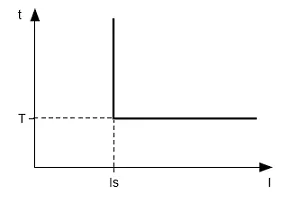
Figure 3.1 – Principle of protection with definite time delay
Protection with dependent time delay:
Protection with dependent time delay corresponds to the standards IEC 60255-3 and BS 142.
- In corresponds to the set-point “Rated Inom” (motor rated current);
- T (“Imax delay” parameter is time constant of the protection operation) corresponds to time delay of tripping for 10×In.
For very large currents the protection has a feature with definite time delay.
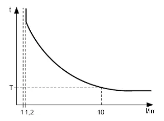
Figure 3.2 – Principle of protection with dependent time delay
Appendix A provides curves for the time constant of the protection to equal 1 second (“Imax delay” parameter). When setting the different value of the time constant, the response time of the protection is changed proportional to the time constant (for example, when “Imax delay” = 10 seconds, operating time of protection at the same ratio of currents will increase 10 times).
3.4.3 Ground fault protection
Section titled “3.4.3 Ground fault protection”- It is enabled when ground-fault current reaches the tripping threshold (“I earth tresh” parameter);
- the motor switches off if the ground-fault current is more than specified for the time T (“I earth delay” parameter).
3.4.4 Negative-sequence current protection (imbalance)
Section titled “3.4.4 Negative-sequence current protection (imbalance)”Negative-sequence current protection (imbalance) is enabled when a component of the negative sequence is more than the set-point (“I2 rev tresh” parameter) and stops the motor when time of this excess is more than specified value (“I2 rev delay” parameter).
If the analysis of tripping cause is enabled (“A-s I2 prot”=“On”), then in case of protection tripping due to exceeding of negative sequence current not because of line voltages imbalance (in this case the motor problems are assumed), ARS after tripping will not occur (regardless of the value of “I2 rev protec” parameter).
The coefficient of negative voltage (current) sequence is characteristic of unbalance of three-phase voltage (current). Approximately the coefficient of negative voltage sequence is determined by the formula:
Where:
- — RMS value of negative voltage sequence of fundamental frequency of three-phase voltage system in i-observation, V;
- — RMS value of positive voltage sequence of fundamental frequency in i-observation, V.
is calculated by the approximate formula:
where , — maximum and minimum RMS values of the three phase-to-phase voltage of the fundamental frequency in i-observation, V.
The coefficient of negative current sequence is calculated similarly.
If currents imbalance is caused not by voltage imbalance, then motor fault is determined. To determine the cause of currents imbalance it is necessary to calculate the ratio of the coefficient of negative current sequence to the coefficient of negative voltage sequence (). And if the ratio is more than the value of “A-s I2 coef” parameter, then UBZ considers that the motor has malfunction.
3.4.5 Minimum phase current protection
Section titled “3.4.5 Minimum phase current protection”- it is enabled when the currents of all three phases drops lower than the set-point (“Imin tresh” parameter) and stops the motor when this drop time is more than the specified one (“Imin delay” parameter);
- it is not active when the load current is less than 10% In (when decrease of the current is due to motor shutdown, not due to decrease of its load);
- It has its own definite time delay of ARS (“AR time Imin” parameter).
3.4.6 Delayed start and rotor blocking
Section titled “3.4.6 Delayed start and rotor blocking”The principle of delayed start protection and rotor inter-blocking is given in Figure 3.3.
3.4.6.1 Delayed start
During start-up the protection is enabled when all phase currents are more than the set-point Is (“Start I Coef” parameter) during the period of time more than the ST time delay (“Start delay I” parameter).
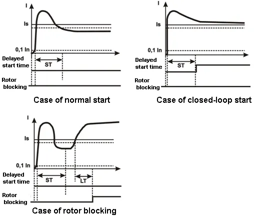
Figure 3.3 – Delayed start and rotor blocking
3.4.6.2 Rotor blocking
After motor start performing (reducing the starting current lower than 1.2 of rated one) UBZ switches to control of possible blocking of the rotor. The protection system operates when all the phase currents are more than set-points during a period of time greater than LT time delay (“Block I delay” parameter).
3.4.7 Thermal overload protection
Section titled “3.4.7 Thermal overload protection”Thermal overload protection is made on the basis of the equation solution of motor thermal balance under the following assumptions:
- before the first start the motor was cold;
- during the motor operation, heat generates that is proportional to the square of the current;
- after motor turning off it is cooled down exponentially.
For protection, you should enter the response time in case of double overload T2 (the parameter of “Thermal delay”).
Current-time characteristic with different values of T2 is given in Figure 3.4.
For the standard recommended T2 value (60 s at 2 time overload) the following current-time characteristic applies:
| I/Inom | 1.1 | 1.2 | 1.4 | 1.7 | 2 | 2.7 | 3 |
|---|---|---|---|---|---|---|---|
| T sec | 365 | 247 | 148 | 88.6 | 60 | 36.4 | 24.6 |
| I/Inom | 4 | 5 | 6 | 7 | 8 | 10 | 15 |
|---|---|---|---|---|---|---|---|
| T sec | 13.5 | 8.5 | 5.9 | 4.3 | 3.3 | 2.1 | 0.9 |
For rotating machines, cooling is more efficient during operation than during the stop of the motor, so enter the parameter “Thermal C stop” - the constant increase rate of cooling when the motor is stopped.
After the load relay disabling owing to thermal overload with ARS permitted, the relay will be enabled again after the time more than the maximum of the two values:
- time of thermal hysteresis (motor should cool down to 33% of the accumulated heat);
- time of ARS.
Choosing different ARS time periods considering thermal hysteresis, one can reduce the number of starts per time device because in the intermittent mode of operation UBZ remembers the amount of heat released during the motor start.
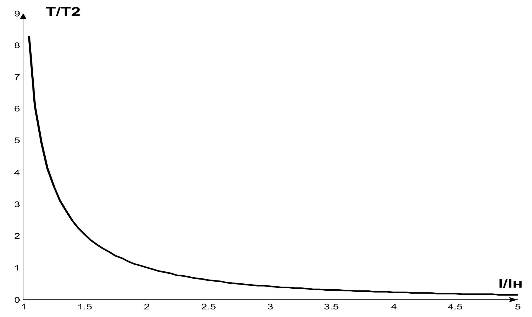
Figure 3.4 – Current-time characteristic
Where:
- I/Iн – current ratio relative to rated one;
- Т/Т2 – the actual response time relative to T2 (response time when double overload).
3.4.8 Windings overheating protection
Section titled “3.4.8 Windings overheating protection”3.4.8.1 The first input protection:
- when working with motor built-in temperature transmitters (parameter “Temp S1 Type”=“R>1.7”) protection is enabled when the transmitter resistance will be more than 1700 Ohms. Set-point “Temp S1 Off M” is not used: short-circuit and breakout of the transmitter is not controlled;
- when working with transmitters of PTC type (1kOhm at 25°C) (“Temp S1 Type” = PTC parameter), protection is enabled and stops the motor when the monitored temperature is more than the set-point (“Temp S1 Off M” parameter).
When working with PTC type transmitters, protection defines the cases of breakout and short circuit of the transmitter:
- the breakout at the temperature higher than 100°C;
- short circuit at the temperature less than minus 45°C.
3.4.8.2 The second input protection:
- it is enabled when the controlled temperature is higher than set-point;
- it has two independent set-points: the alarm set-point (“Temp S2 Alarm” parameter) and the set-point for the motor is off (“Temp S2 Off M” parameter).
Protection determines the cases of breakout and short circuit of the temperature transmitters:
- breakout at temperature of more than 220°C;
- short circuit at temperature of less than minus 45°C.
On the second input the protection is operated with temperature transmitters of Pt100 type (platinum type for 100 Ohm at 0°C) or Ni100 (Ni120) (Nickel type for 100 Ohm (120 Ohm) at 0°C) in accordance with the standards of IEC 60751 and DIN 43760.
3.4.9 Voltage protection
Section titled “3.4.9 Voltage protection”In UBZ voltage protection before enabling the load it is necessary to check the corresponding set-points and depending on their value, the load relay enabling will be permitted or disabled; when the motor is on, the voltage control is fulfilled, but the decision relative to disabling is made according to currents.
The voltage protections are the following:
- at minimum line voltage (it is enabled if at least one of the line voltages is less than the set-point (“Umin tresh” parameter) within the time specified by “Umin delay” parameter);
- at maximum line voltage (it is enabled if at least one of the line voltages is more than the set-point (“Umax tresh” parameter) within the time specified by “Umax delay” parameter);
- during line voltages imbalance (it is enabled if the difference between effective values of the line voltages is more than the set-point (“Uimbal tresh” parameter) within the time specified by “Uimbal delay” parameter).
3.4.10 Phase sequence protection
Section titled “3.4.10 Phase sequence protection”Phase sequence protection (“Correct phase” parameter) is enabled in case of improper phase sequence; it disables the motor and blocks its further operation.
3.4.11 Network power frequency drop protection
Section titled “3.4.11 Network power frequency drop protection”Network power frequency drop protection is enabled, if the network power frequency is less than the set-point (“Frequency Min” parameter) within the time specified by “FreqMin delay” parameter.
3.4.12 Network power frequency rise protection
Section titled “3.4.12 Network power frequency rise protection”Network power frequency rise protection is enabled, if the network power frequency is higher than the set-point (“Frequency Max” parameter) within the time specified by “FreqMax delay” parameter.
3.4.13 Protection for minimum resistance of motor winding insulation
Section titled “3.4.13 Protection for minimum resistance of motor winding insulation”After UBZ energizing before the output relay will be on, it is necessary to check the insulation level of stator winding relative to the housing. The level of stator winding insulation relative to housing is also checked, when the load relay is on, but the motor currents are less than 10% of rated current (in this case UBZ considers that the motor is off).
When “Insulation Mr” = “5 AR” (“5 nAR”) the load is disabled if the insulation resistance is lower than 500 kOhm ±20 kOhm, and when “Insulation Mr” = “10 AR” (“10 nAR”) if it is less than 1000 kOhm ±50 kOhm. During automatic restarting “AR”, the load will on after restoring the insulation resistance and after ARS time finishing. If “nAR”, ARS will not on.
3.4.14 Protection for the motor phase(-s) break (loss)
Section titled “3.4.14 Protection for the motor phase(-s) break (loss)”Protection for the motor phase(-s) break (loss) is enabled, if one of the motor phase current is more than 10% of the rated one (“Rated Inom” parameter), and any of the remaining phases of the motor is less than 7% of the motor rated current.
3.4.15 Serviceability check of external magnetic starter
Section titled “3.4.15 Serviceability check of external magnetic starter”UBZ detects the motor currents when the load relay is off (if the load relay and functional relay is off in star-delta mode). In this case, UBZ indicates the fault of external MS enabling the motor, until then UBZ is turned off or control of the motor currents is disabled when load relay is off (Cont Cont = 0 (“Off”) parameter).
4. UBZ Design
Section titled “4. UBZ Design”UBZ is microprocessor-based digital device that provides a high degree of reliability and accuracy. Operational power is not required. The controlled voltage is simultaneously the power supply voltage.
5. Intended Use
Section titled “5. Intended Use”5.1 Preparation for operation
Section titled “5.1 Preparation for operation”5.1.1 Preparation for connection
Section titled “5.1.1 Preparation for connection”- Unpack the device (we recommend to keep the original packing for the entire warranty period of the device operation);
- Check the device for damage after transportation; in case of such damages detection, contact the supplier or manufacturer;
- Check for components (Section 2), in case of detection of incomplete device, contact the supplier or manufacturer;
- Carefully study the Operating Manual (pay special attention to the connection diagram to power the device);
- If you have any questions regarding the installation of the device, please contact the manufacturer by telephone number indicated at the end of this Operating Manual.
5.1.2 Selection of Current Transformers (CT)
Section titled “5.1.2 Selection of Current Transformers (CT)”- Rated output current of CT should be 5A.
- Rated input current of CT (Ict) is selected based on the rated current of the motor (In), the motor starting current, start duration, the time required for ARS (taking into account the characteristics of UBZ inputs designed to connect CT (Table 5.1)).
Table 5.1 – Characteristics of UBZ-304 inputs designed to connect CT
| Current of UBZ inputs designed for measurement of CT output currents, A | Ratio of overload relative to rated current (5A) | Maximum duration of current action, s | Minimum delay before restarting, s |
|---|---|---|---|
| 0 – 12 | 2.4 | continuously | – |
| 12 – 15 | 3 | 60 | 10 |
| 16 – 20 | 4 | 30 | 15 |
| 21 – 25 | 5 | 15 | 30 |
Rated input current of CT should be within the range: In < Ict < 3×In.
It is recommended to use CT with Ict = 2×In.
5.1.3 General
Section titled “5.1.3 General”To ensure the reliability of electrical connections you should use flexible (stranded) wires with insulation for voltage of not less than 450V, the ends of which it is necessary to be striped of insulation for 5±0.5 mm and tightened with bootlaces. Recommended cable cross section for connection is not less than 1 mm².
Wires fastening should exclude mechanical damage, twisting and insulation abrasion of wires.
IT IS NOT ALLOWED TO LEAVE EXPOSED PORTIONS OF WIRE PROTRUDING BEYOND THE REMOVABLE TERMINAL BLOCK.
For reliable contact it is necessary to perform tightening of screws of removable terminal block with the force specified in Table 2.
To improve performance properties of UBZ, it is recommended to install fuses (fusible elements or their analogues) in the following circuits (listed in the order required; a hyphen is the recommended fuse value):
- UBZ power supply circuits (34, 35, 36 – L1, L2, L3) – 1 A;
- circuits for measurement of temperature, current, voltage (1 - 9) – 0.5 A;
- RS-485 (10 - 12) – 0.5 A.
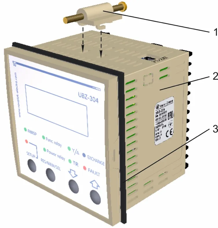
Figure 5.1 – UBZ Installation
- fastener
- UBZ
- rubber gasket
5.1.4 Device Installation
Section titled “5.1.4 Device Installation”5.1.4.1 UBZ is the device of panel design version.
The panel design should meet the following requirements:
- the hole for UBZ installation is square-shaped of 91.5×91.5 mm (+0.5mm tolerance);
- the distance between UBZ panels (top, bottom and side) and the relevant surfaces of the panel should be at least 10 mm;
- if it is assumed to have operational use of communication via RS-232, the distance between the top panel of UBZ and the corresponding surface of the panel should be at least 30 mm.
5.1.4.2 Installation procedure:
- put the rubber gasket on UBZ (item 3 in Figure 5.1);
- install UBZ into the panel hole;
- install the fasteners (item 1 in Figure 5.1) on the lower and upper UBZ panels;
- secure UBZ in the panel with tightening screws of the fastener.
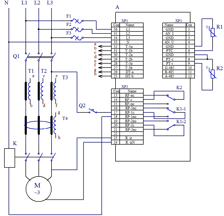
Figure 5.2 – UBZ-304 Connection Diagram
- A – UBZ
- F1-F3 – Fusible element for 1 А (or its equivalent)
- K – Magnetic starter (MS)
- R1 – Temperature transmitter (for example: PTC1000, EKS111 made by DANFOSS)
- R2 – Temperature transmitter (for example: PT100)
- Q1, Q2 – automatic breaker
- T1-T3 – Current transformer (output 5 A)
- T4 – Differential transformer
5.1.5 UBZ-304 connect
Section titled “5.1.5 UBZ-304 connect”5.1.5.1 Connect the current transformers in accordance with Figure 5.2;
5.1.5.2 Pass through a differential current transformer (zero sequence transformer) all three phase wires and connect it to UBZ;
5.1.5.3 To monitor and measure the motor insulation, connect the control terminal of the insulation 23 to one of output contacts of MS. If the motor housing is not grounded, or network with isolated neutral is used, or neutral wire is not connected to UBZ terminal, it is necessary to connect electrically the motor housing to the terminal 24 of UBZ.
5.1.5.4 Connect the motor to UBZ in accordance with Figure 5.2. When using the motor with the switching over the windings during star-delta starting-up, perform the connection in accordance with Appendix B.
5.1.5.5 To work with UBZ from personal computer as the control or supervising using the program of “UBZ-304/305 Control Panel” it is necessary:
- download the program of “UBZ-304/305 Control Panel” from the manufacturer’s web-site (https://novatek-electro.com/en/software/control-panel-of-ubz-304305.html);
- to install on the PC the program of “UBZ Control Panel”, starting the program “Setup_cplubz304(Х.Х).exe” (X.X – number of software version);
- to connect “RS232” connector on the top panel of UBZ to RS-232 connector of PC using the cable KC-01;
- to set the parameter of “Communication” = “RS232”.
5.1.5.6 In case of MODBUS usage, connect the communication lines to terminals 10 (GND), 11 (line B RS-485), 12 (line A RS-485) of UBZ. Set the parameter of “Communication” = “RS485”.
5.1.5.7 Energize UBZ-304
The enabling sequence for the load relay after energizing is determined by the values of the parameters “AR time” and “Start>Power”.
5.1.5.8 In the course of first starting in accordance with factory settings UBZ is in the mode of MNS in which it is possible to set the following parameters:
- CT rated current (parameter of “CT nom i”);
- motor rated current (parameter of “Rated Inom”).
For normal operation of UBZ it is enough to set these parameters according to used CT and the motor.
5.1.5.9 Disable power of UBZ;
5.1.5.10 Connect the magnetic starter (hereinafter referred as MS) of the motor in accordance with Figure 5.2.
5.2 UBZ Control
Section titled “5.2 UBZ Control”5.2.1 Modes of UBZ control and status
Section titled “5.2.1 Modes of UBZ control and status”UBZ has five control modes:
- Keyboard blocking
- MNS
- User level
- Advanced user level
- Remote control
All the modes of control have possibility to switch UBZ in the state:
- Viewing the measured and calculated parameters (Table 3.5)
- Viewing the faults logbook
5.2.2 Measured and calculated parameters view state
Section titled “5.2.2 Measured and calculated parameters view state”Measured and calculated parameters view state is the principal state. From all other modes UBZ returns to this mode automatically (if after 30 s, no button is pressed).
In this mode the first three lines of the indicator displays a group of three functionally close settings (when adding the values of temperature transmitters or analog inputs – a group of two parameters) (Figure 5.3).
The information displayed in the fourth line of the indicator depends on the state of UBZ.
If the load relay is enabled, then the fourth line of the display shows the current time (Figure 5.3).
If the load relay is off, then the fourth line of the indicator can display the following:
- “AR=NOT Ir=0 15:30:17” in case if the motor start is impossible as the motor rated current is not set (parameter of “Rated Inom” =0);
- “AR=NOT 15:30:17” in case if the fault occurred after which ARS is disabled;
- “AR=350 15:30:17” in case if the fault occurred and ARS is possible (ARS time account is on – 350 s left to ARS).
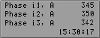
Figure 5.3 – UBZ Indicator in view mode of measured and calculated parameters (load relay is on)
The display shows:
- In line 1 – current in phase L1 – 345 А
- In line 2 – current in phase L2 – 350 А
- In line 3 – current in phase L3 – 342 А
- In line 4 – current time
In the second and third variant, information of the fourth line of the indicator is consistently changing – in addition to reports about the possibility of starting the motor; it displays the total number of faults and type of fault on the display (Figure 5.4). For example, if the information on the indicator corresponds to Figure 5.4, then in 2s the fourth line displays the fourth type of fault.
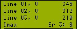
Figure 5.4 – UBZ Indicator in view mode of measured and calculated parameters (in fault conditions)
The display shows:
- In line 1 – line voltage U1 – 345 V
- In line 2 – line voltage U1 – 312 V
- In line 3 – line voltage U1 – 210 V
- In line 4 – “Imax” – type of fault (over-current protection); “Er 3:8” – the indicator displays the third fault; total number of existing types of faults is 8
5.2.3 Mode of ‘Keyboard blocking’
Section titled “5.2.3 Mode of ‘Keyboard blocking’”When the keyboard is blocked you cannot view and reinstall the programmable parameters.
When the keyboard is blocked, pressing the SETUP button leads to the appearance on the indicator the message “blocked buttons” (Figure 5.5).

Figure 5.5 – Indicator when the keyboard is blocked
To unblock the keyboard, it is necessary to press again the SETUP button. The led turns on SETUP, and the indicator displays the inscription “USERS PASSWORD” and “<0>”. With the help of UP and DOWN buttons you can dial the digit of user password from 1 to 9 and can press the button RES/MEM/SEL. If the password is correct, the keyboard is unblocked. If after unblocking the keyboard no button is pressed within 15 s and setting of blocking has not been disabled by the user, the keyboard is blocked again.
5.2.4 Mode of ‘Minimum number of settings’ (MNS)
Section titled “5.2.4 Mode of ‘Minimum number of settings’ (MNS)”Mode of MNS is designed to facilitate the work of the service personnel with UBZ.
In case of initial factory settings UBZ is in the mode of MNS.
When UBZ is operated in the mode of MNS the green led MMSP is on.
UBZ operation in MNS mode differs from UBZ operation in the mode of user level that the parameters not included in the list of MNS are set to factory defaults, and when you log in the user menu they are not visible.
Operation with parameters those are included in the list of MNS is the same as with the settings in the mode of user level.
When the mode of MNS is disabled (setting of parameter “Minimal set” is in “Off” position), the led MMSP goes out and UBZ switches to the user level. At the user level you can change all the settings (included and not included in the list of MNS), if the change is not disabled by the advanced user.
Adding of any parameter in the list of MNS and disabling of MNS mode is possible only in advanced user level.
UBZ will transfer to the MNS mode after reset to factory settings.
5.2.5 Mode of ‘User level’
Section titled “5.2.5 Mode of ‘User level’”When UBZ device is in the user-level mode, led MMSP is off.
To view and change the parameters of user level you should press the SETUP button, the led SETUP is on and the indicator displays the user menu (Figure 5.6).

Figure 5.6 – User’s Menu
Using DOWN and UP buttons select the desired parameter (in Figure 5.6, “CT nom i” parameter is selected; it is the rated current of the CT) and press the “SETUP” button (Figure 5.7).

Figure 5.7 – Screen of changing the setting in the user mode
If the fourth line of the indicator is marked by “ADV” (Figure 5.7), the change of the parameter value in the user mode is disabled and, in this case, it can only be changed in the mode of “Advanced user level”.
If the parameter is not in the list of MNS (the fourth line of the indicator has the inscription “OFF MMSP”), then to change the value of the parameter it is necessary preliminary to include it in the list of MNS.
To do this it is required the following:
- using DOWN and UP buttons select the parameter;
- press SETUP button;
- press simultaneously DOWN and UP buttons (on the display instead of the inscription “OFF MMSP” the inscription “MMSP” should remain).
The value of the parameter in the user mode can be changed if the fourth line of the indicator has only the inscription “MMSP”. To do this it is required:
- using buttons DOWN or UP select the desired parameter value;
- using the button RES/MEM/SEL, record the value of the parameter, and to go back to menu without recording, press the SETUP button.
If no button is pressed within 30 seconds, UBZ switches to the state of the viewing the measured and the calculated parameters.
To exit to menu before 30 seconds you need to press button RES/MEM/SEL.
5.2.6 Mode of “Advanced user level”
Section titled “5.2.6 Mode of “Advanced user level””Access to the advanced user level:
- Press the SETUP button for 5 seconds, release the button.
If the level is password protected, the led SETUP is on and the display shows the “PASSWORD” inscription and “000” will flash (Figure 5.8).

Figure 5.8 – Advanced user password
- Using UP and DOWN buttons sequentially, enter the three-digit password of advanced user, from 1 to 9 and separate dialing with pressing the button RES/MEM/SEL. If the password is wrong, then UBZ will return to the view state of the parameters, otherwise UBS will go to the advanced user level (Figure 5.9).
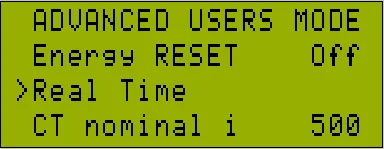
Figure 5.9 – Advanced user level
The procedure for changing the settings on the advanced user level is the same as user-level, but the parameter recording does not depend on the inscription “ADV” presence in the fourth line of the indicator.
If the parameter is not in the list of MNS (the fourth line of the indicator has the inscription “OFF MMSP”), then to change the value of the parameter it is necessary preliminary to include it in the list of MNS.
At the advanced user level, the availability of any parameter at the user level can be disabled or enabled.
To do this it is required the following:
- using DOWN and UP buttons, select the parameter (Figure 5.9);
- enter the menu where setting is changed by pressing SETUP button;
- press both buttons SETUP and DOWN.
In case of restricting access to change the parameter at the user level in the fourth line of the indicator the inscription “ADV” will display.
5.2.7 Factory settings
Section titled “5.2.7 Factory settings”Factory settings are possible in two ways.
The first method: set the parameter “Default Factor” to “On”; after exiting from the mode for setting the factory settings will be restored.
This method does not recover the following settings:
- access code of advanced user (“Password”);
- current time and date;
- clock correction (“Correct Time”);
- the device operating time (“Time UBZ”);
- operating time of the motor (“Time motor”).
The second method: when UBZ energizing, hold pressed for two seconds the buttons SETUP and RES/MEM/SEL. Factory settings are restored (advanced user password - 123).
This method does not recover the following settings:
- the device operating time (“Time UBZ”);
- operating time of the motor (“Time motor”);
- clock correction (“Correct Time”).
After you complete the installation of factory parameters, UBZ will start operation in the mode of MNS, the list of which the settings are included:
- motor rated current, “Rated Inom”
- current time setting, “Real Time”
- CT current, “CT nom i”
5.2.8 Real time setting
Section titled “5.2.8 Real time setting”To set the real time it is necessary the following:
- pressing SETUP button, enter the parameters setting mode;
- using UP and DOWN buttons, select parameter “Real Time”;
- press the button SETUP (Figure 5.10);

Figure 5.10 – View of the display when setting the time
- using UP and DOWN buttons, select the desired date and press the button RES/MEM/SEL;
- repeat step 4 to set the month, year, hour and minute.
When recording minutes (at the moment of pressing the button RES/MEM/SEL), the number of seconds will be automatically set to zero.
If you move to the next parameter without changes, instead of the button RES/MEM/SEL, press the button SETUP.
If no button is pressed for 15 seconds, UBZ will automatically switch to the parameter view mode.
5.2.9 UBZ faults reset on front panel
Section titled “5.2.9 UBZ faults reset on front panel”Fault reset is performed when the motor is off. To reset the faults on the front panel, press simultaneously the buttons SETUP and DOWN, in this case:
- faults are reset regardless of whether ARS is disabled or enabled (besides the current faults and faults by the presence of motor currents when load relay is off);
- counting of ARS is off;
- in the absence of the current troubles the motor is off.
5.2.10 Energy meters reset
Section titled “5.2.10 Energy meters reset”Reset of energy meters (total, active and reactive) is performed when setting the parameter “Energy RESET” to “On” (setting to “1” when using RS-232/RS-485 interface). After reset of energy meters, the parameter “Energy RESET” will automatically switch to “Off” (“0” – when reading the parameter via RS-232/RS-485 interface).
5.3 UBZ Operation
Section titled “5.3 UBZ Operation”In describing the operation of UBZ it is assumed that this protection is enabled and all the required sensors are connected.
5.3.1 UBZ operation before load relay on
Section titled “5.3.1 UBZ operation before load relay on”5.3.1.1 UBZ operation after energizing (first start-up)
After energizing the indicator displays the device name, the version number of software, the name of the manufacturer and the operation performed (Figure 5.11).
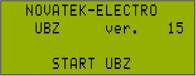
Figure 5.11 – UBZ indicator view after energizing
After 1-2 seconds the indicator will display the values of the measured parameters. What parameters will be displayed on the indicator it depends on the value of the parameter “Indicat <Start”:
- line voltages at “Indicat <Start”=“LineU”;
- the motor operating time, the insulation resistance of the motor and mains frequency at “Indicat <Start”= “InsFr”.
Before the load relay enabling UBZ checks the following:
- the level of stator winding insulation relative to the motor housing (when insulation resistance is less than 500 ± 20 kOhm at “Insulation Mr” = “5” (1000 ± 50 kOhm at “Insulation Mr” = “10”) the load is not enabled);
- the quality of the mains voltage: full phase, symmetry, the current line voltage value;
- correct phase sequence, the lack of their “coincidence”.
If any of disabling factors, the load relay is not activated, and the display of mnemonics shows the corresponding message about the fault (Table 5.13) and the led FAULT lights up.
In the absence of disabling factors, enabling the load relay is determined by the value of parameter “Start>Power” (UBZ operation after energizing):
- when “Start>Power” = “StOff”, the load relay will not be enabled. To enable the load relay in this case, you should simultaneously press UP and DOWN buttons.
- when “Start>Power” = “St>AR” the load relay will be enabled after ARS time.
- when “Start>Power” = “St>2s” the load relay will be enabled within 2 seconds after energizing.
Simultaneously with the load relay enabling the green led “Power relay” lights up.
After you activate the relay and up to the moment of the motor starting (motor start is determined by the excess of the load current of 120% level of rated current), control and taking action on voltage quality is maintained. If within no-current pause the disabling factors are appeared, the load relay is deactivated.
UBZ operation when enabled remote control of the motor via RS-232/RS-485 interface (parameter “MotorOp RS-2/5”) is considered in Section 5.4.9.
5.3.1.2 UBZ operation after shutdown owing to the fault
UBZ operation in this case is similar to the work when first starting, but enabling the load relay does not depend on the value of the parameter “Start>Power”.
If after the fault ARS is disabled (“AR”=“Off”), then with disabled motor start on the front panel (it is determined by the value of the parameter “MotorOp UBZ”) the automatic enabling the motor is impossible up to UBZ turning off. The action of the parameter “AR” value is applied to all types of faults except voltage faults. To disable ARS in case of voltage faults you should use the parameters “Umax protec”, “Umin protec”, “Uimbal protec”.
5.3.2 UBZ operation after load relay enabling and motor is on
Section titled “5.3.2 UBZ operation after load relay enabling and motor is on”UBZ provides monitoring for voltage and currents. The load relay is disabled when any protection tripping from Table 5.13 with the exception of:
- voltage protection;
- overcurrent protection with “Imax<>T” =“Ind” (in this case, the warning is there, but the load relay is not disabled).
The indicator can display phase currents of motor or group of three (two) parameters selected by the user (Table 3.5).
The group of parameters selected by the user can be displayed constantly (“Indicat mode” = “Conti”) or for 15 s, and then indication of motor currents returns (“Indicat mode” = “>15s”).
5.3.3 Functional relay operation
Section titled “5.3.3 Functional relay operation”The functions performed by the functional relay are determined by the parameter “Relay F mode”.
When “Relay F mode” = “Alarm”, the relay is used as alarm relay (LEDs Y/△ and TR do not on). The relay contacts are closed when there is any fault specified in Table 5.13.
When “Relay F mode” = “Timer”, the relay is used as time relay (LED TR is on): it turns on after the time set by the parameter “Relay F time”, after the load relay enabling.
When “Relay F mode” = “St->D”, the relay is used to switch the motor windings from star to delta (LED Y/△ is on). In this mode the load relay is activated the same way as in the mode “Relay F mode”=“Alarm”, but after the time set by parameter “Relay F time” it is disabled. After the time set by the parameter “Delay RP RF”, after the load relay is off, the functional relay is activated.
5.4 Operation of UBZ-304 together with computer
Section titled “5.4 Operation of UBZ-304 together with computer”5.4.1 Communication protocol and interface
Section titled “5.4.1 Communication protocol and interface”The communication between UBZ and computer can be via RS-232 or RS-485 interface (parameter “Communication”).
For communication MODBUS Protocol is used in RTU mode or MODBUS in ASCII mode (parameter “ASCII-RTU”).
In ASCII mode 8-bit data is the combination of two ASCII characters (Table 5.2). For example, 1-data byte: 64 Hex, in ASCII consists of two characters ‘6’ (36 Hex) and ‘4’ (34 Hex).
Table 5.2 – ASCII Character Encoding
| Character | ’0' | '1' | '2' | '3' | '4' | '5' | '6' | '7’ |
|---|---|---|---|---|---|---|---|---|
| ASCII code | 30 Hex | 31 Hex | 32 Hex | 33 Hex | 34 Hex | 35 Hex | 36 Hex | 37 Hex |
| Character | ’8' | '9' | 'A' | 'B' | 'C' | 'D' | 'E' | 'F’ |
|---|---|---|---|---|---|---|---|---|
| ASCII code | 38 Hex | 39 Hex | 41 Hex | 42 Hex | 43 Hex | 44 Hex | 45 Hex | 46 Hex |
In RTU mode 8-bit data is the combination of 4-bit hexadecimal digits. For example, 64 Hex.
During data exchange via RS-485 or RS-232 the blue LED EXCHANGE is on.
Diagram of UBZ connection to computer is shown in Figure 5.12.
Each UBZ has the individual communication address. The computer controls each UBZ recognizing them by their addresses.
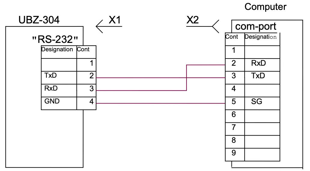
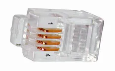
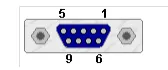
Figure 5.12 – Diagram of UBZ connection to computer
5.4.2 Communication parameters
Section titled “5.4.2 Communication parameters”- the device address: 1-247 (parameter “Address UBZ”);
- data transfer rate: 9600 baud, 19200 baud (parameter “Data speed”);
- reaction to loss of connection: the continuation of operation with no warning, the warning and continued operation, the warning and stopping the motor with ARS enabling after restoration of communication, warning and motor stop with ARS disabling (parameter “Loss connect”);
- detection of exceeded time for reply: 1s – 120s (parameter “Overexceeding”).
The format of the transmitted word is the following:
- 8 data bits in RTU mode and 7 data bits in ASCII mode;
- parity check (parameter “Even parity”): disabled (“Off”), enabled (“On”); (factory setting is “Off”);
- number of stop bits (parameter “Stop bit”): 1 or 2 (factory setting is 2).
5.4.3 Communication protocol
Section titled “5.4.3 Communication protocol”Exchange between PC and UBZ is carried by data packets. Data packet format in RTU mode is shown in Table 5.3 and in ASCII mode – in Table 5.4.
Table 5.3 – Data packet in RTU mode
| Name | Description |
|---|---|
| START | Silence interval – over 4 ms at transmission rate of 9600 baud, or more 2 ms at transmission rate of 19200 baud |
| ADR | UBZ communication address (8 bit) |
| CMD | Command code (8 bit) |
| DATA 0…DATA (n-1) | Content of data: N×8 bit data (n≤24) |
| CRC CHK low | CRC – Cyclic Redundant Check (16 bit) |
| CRC CHK high | |
| END | Silence interval – over 4 ms at transmission rate of 9600 baud, or more 2 ms at transmission rate of 19200 baud |
Table 5.4 – Data packet in ASCII mode
| Name | Description |
|---|---|
| STX | Start character ’:’ (3A Hex) |
| ADR1, ADR0 | UBZ communication address (8 bit) consisting of two ASCII characters |
| CMD1, CMD0 | Command code (8 bit) consisting of two ASCII characters |
| DATA 0…DATA (n-1) | Content of data: N×8 bit data (n≤24) consisting of two ASCII characters each |
| LRC CHK 1, LRC CHK 0 | LRC Cyclic Redundant Check: 8-bit control total consisting of two ASCII characters |
| END1 | Carriage return CR (0D Hex) |
| END0 | Line feed LF (0A Hex) |
5.4.4 Command codes
Section titled “5.4.4 Command codes”5.4.4.1 General
Section titled “5.4.4.1 General”The format of data characters depends on command codes. Examples of transmission of commands and data are given for RTU mode. For ASCII mode the command codes are not changed, but the format of the transmission data and control of data is based on the Table 5.4.
5.4.4.2 Command for reading the register group
Section titled “5.4.4.2 Command for reading the register group”Command code – 0x03, reading n-words
For example, reading of continuous 2 words from starting address 2102H in UBZ with communication address 01H in RTU mode (Table 5.5) and in ASCII mode (Table 5.6).
Table 5.5 – Example of reading register group (RTU mode)
| Command Message | Value | Response Message | Value |
|---|---|---|---|
| ADR | 0x01 | ADR | 0x01 |
| CMD | 0x03 | CMD | 0x03 |
| Start address (high) | 0x21 | Number of data in bytes | 0x04 |
| Start address (low) | 0x02 | Data at address (high) | 0x17 |
| Number of words (high) | 0x00 | Data at address (low) | 0x70 |
| Number of words (low) | 0x02 | Data at address+1 (high) | 0x00 |
| CRC CHK low | 0x6F | Data at address+1 (low) | 0x00 |
| CRC CHK high | 0xF7 | CRC CHK low | 0xFE |
| CRC CHK high | 0x5C |
Table 5.6 – Example of reading register group (ASCII mode)
| Command message | Character | Code transferred, HEX | Numbers for LRC, HEX |
|---|---|---|---|
| STX | ’:‘ | 3A | |
| ADR | ’0’, ‘1’ | 30, 31 | 01 |
| CMD | ’0’, ‘3’ | 30, 33 | 03 |
| Start address of data | ’2’, ‘1’, ‘0’, ‘2’ | 32, 31, 30, 32 | 21, 02 |
| Number of data in words | ’0’, ‘0’, ‘0’, ‘2’ | 30, 30, 30, 32 | 00, 02 |
| LRC CHK 1, LRC CHK 0 | ’D’, ‘6’ | 44, 36 | |
| END1 | CR | 0D | |
| END0 | LF | 0A |
5.4.4.3 Command of register entries
Section titled “5.4.4.3 Command of register entries”Command code – 0x06, record – one word
Data recording is possible at the addresses of programmable parameters (Table 3.6), except the parameters listed in Table 5.7.
The parameter recording is independent of set protection of the advanced user (entry by the communication line has higher priority).
When recording new value of the parameter into the cell protected by MNS, the parameter is automatically removed from this mode.
Table 5.7 – Parameters not available for writing
| Settings and readings | Displaying | Address |
|---|---|---|
| Total time of device operation, day | Time UBZ | 217 |
| Motor operating time, day | Time motor | 218 |
| Access code of user | Users code | 219 |
| Access code of advanced user | Password | 220 |
| Restoration of factory settings | Default Factor | 221 |
| Device design version | Version | 230 |
Example: recording order is 1000 (0x03E8) to register with address 0x00A0 to UBZ with communication address 01H in RTU mode is shown in Table 5.8.
Table 5.8 – Example of writing to register (RTU mode)
| Command Message | Value | Response Message | Value |
|---|---|---|---|
| ADR | 0x01 | ADR | 0x01 |
| CMD | 0x06 | CMD | 0x06 |
| Start address (high) | 0x00 | Start address (high) | 0x00 |
| Start address (low) | 0xA0 | Start address (low) | 0xA0 |
| Data (high) | 0x03 | Data (high) | 0x03 |
| Data (low) | 0xE8 | Data (low) | 0xE8 |
| CRC CHK low | 0x89 | CRC CHK low | 0x89 |
| CRC CHK high | 0x56 | CRC CHK high | 0x56 |
5.4.4.4 Command for diagnostics
Section titled “5.4.4.4 Command for diagnostics”Command code 08h – diagnostics
The 08h function provides a number of tests for checking the communication system between PC and UBZ, and UBZ serviceability control.
The function uses the sub-function field to specify the action performed (test).
Sub-function 00h – return of request data
The data transmitted in the data field of the request should be returned in the response data field.
Example of request and response for MODBUS RTU mode:
| Address | Function | Sub-function HB | Sub-function LB | Data HB | Data LB | CRC LB | CRC HB | |
|---|---|---|---|---|---|---|---|---|
| Request | 01h | 08h | 00h | 00h | A0h | 3Ch | 98h | 1Ah |
| Response | 01h | 08h | 00h | 00h | A0h | 3Ch | 98h | 1Ah |
Figure 5.13 – Example of request and response for sub-function 00h – return of request data
Sub-function 01h – restart of communication options
During fulfillment of the command UBZ performs only change in baud rate. To change totally the communication settings you should run the command “UBZ RESTART” (“RESTART”).
Example of request and response for MODBUS RTU mode:
| Address | Function | Sub-function HB | Sub-function LB | Data HB | Data LB | CRC LB | CRC HB | |
|---|---|---|---|---|---|---|---|---|
| Request | 01h | 08h | 00h | 01h | 00h | 00h | B1h | CBh |
Response is not returned.
Figure 5.14 – Example of request and response for sub-function 01h – restart of communication options
5.4.5 Control of correct transmission of data packet
Section titled “5.4.5 Control of correct transmission of data packet”5.4.5.1 Control of correct transmission of data packet in RTU mode
Section titled “5.4.5.1 Control of correct transmission of data packet in RTU mode”To check the correctness of data transmission in RTU mode the CRC Cyclic Redundant Check – the code for cyclic control is used.
The Cyclic Redundant Check (CRC16) is a cyclic verification code based on the polynomial A001h. The transmitting device forms the Cyclic Redundant Check for all bytes of the message transmitted. The receiving device similarly generates the Cyclic Redundant Check for all bytes of the message received and compares it with the Cyclic Redundant Check received from the transmitting device. In case of mismatching the generated and received Cyclic Redundant Check the error message will be generated.
The field of Cyclic Redundant Check has two bytes. CRC in the message is transferred with low byte first.
CRC is formed by the following algorithm:
- loading CRC register (16 bit) by devices (FFFFh);
- exclusive OR with the first 8 bits of the byte of the message and CRC register contents;
- shift of the result one bit to the right;
- if shifted bit = 1, exclusive OR of the contents of the register with value A001h;
- if shifted bit = 0, repeat step 3;
- repeat steps 3, 4, 5, until 8 shifts;
- exclusive OR with the following 8 bits byte of the message and CRC register contents;
- repeat steps 3 to 7 until all bytes of the message will be processed;
- the final contents of the register will contain the CRC.
Example of Program CRC code generation in the language C. The function has two arguments:
unsigned char* data– a pointer to the message bufferunsigned char length– the quantity of bytes in the message buffer
The function returns the CRC value as a type of unsigned integer.
unsigned int crc_chk(unsigned char* data, unsigned char length){ int j; unsigned int reg_crc = 0xFFFF; while(length--) { reg_crc ^= *data++; for(j = 0; j < 8; j++) { if(reg_crc & 0x01) reg_crc = (reg_crc >> 1) ^ 0xA001; // LSB(b0)=1 else reg_crc = reg_crc >> 1; } } return reg_crc;}5.4.5.2 Control of correct transmission of data packet in ASCII mode
Section titled “5.4.5.2 Control of correct transmission of data packet in ASCII mode”To check the correctness of data transfer in ASCII mode LRC Redundant Check – longitudinal redundancy check is used. LRC is 8-bit number transmitted as two ASCII characters. The LRC is formed by inverse transformation of all ASCII characters in eight-bit binary numbers, the addition of these numbers without accounting for the transfer, and the calculation of additional code of the received number. At the receiver, the LRC is calculated again and compared with the received LRC. In the calculation of LRC the colon, CR and LF are discarded.
An example of the LRC calculation for the command for reading of continuous 2 words from starting address 2102H in UBZ with communication address 01H is shown in Table 5.6.
5.4.6 Register addresses
Section titled “5.4.6 Register addresses”The register addresses of measured and calculated parameters of UBZ are given in Table 3.5.
The register addresses of programmable parameters are given in Table 3.6.
The register addresses of special and service parameters and their purpose are given in Table 3.4.
The register address of the status and purpose bit data in Table 5.9.
The register addresses of the alarm log are given in Table 5.9.
The register addresses of time settings are given in Table 5.10.
The register address of commands is 903 (Table 5.12).
Table 5.9 – Register addresses for UBZ state and fault logbook
| Description | Address | Service | Description | Remark |
|---|---|---|---|---|
| Register of UBZ state | 900 | Bit 0 | 0 – No fault; 1 – fault (code of fault in register 241) | |
| Bit 1 | 0 – load relay is disabled; 1 – load relay is enabled | |||
| Bit 2 | 0 – functional relay is disabled; 1 – functional relay is enabled | |||
| Bit 3 | 0 – restart is disabled; 1 – ARS is waited | |||
| Bit 5-4 | Mode of functional relay: 00 – alarm relay; 01 – time relay; 10 – star/delta | |||
| Bit 6 | 0 – MNS mode is disabled; 1 – MNS mode is enabled | |||
| Bit 7 | 0 – clock battery is normal; 1 – the clock battery should be replaced | |||
| Bit 8 | 0 – normal operation; 1 – UBZ is in area of hysteresis (analog inputs) | |||
| Register of fault 1 | 901 | Bit service as per Table 5.13 | 0 – no fault; 1 – fault | |
| Register of fault 2 | 902 | Bit service as per Table 5.13 | ||
| Fault logbook | ||||
| Fault code 1 | 1000 | Fault code as per Table 5.13 | ||
| Parameter value 1 | 1001 | Parameter value as per Table 5.13 | ||
| Fault time 1 | 1002 | Low byte – seconds, high byte – minutes | ||
| 1003 | Low byte – hours, high byte – day of month | |||
| 1004 | Low byte – month, high byte – (year minus 2000) | |||
| Fault code N | 1000+(N-1)×5 | Fault code as per Table 5.13 | ||
| Parameter value N | 1000+(N-1)×5+1 | Parameter value as per Table 5.13 | ||
| Fault time N | 1000+(N-1)×5+2 | Low byte – seconds, high byte – minutes | ||
| 1000+(N-1)×5+3 | Low byte – hours, high byte – day of month | |||
| 1000+(N-1)×5+4 | Low byte – month, high byte – (year minus 2000) |
5.4.7 Time parameter registers
Section titled “5.4.7 Time parameter registers”The parameters are transmitted in binary decimal code. For example, the code 0x14 in the register of minutes means 14 minutes.
Registers of time settings allow reading and recording of data.
Register addresses for time settings are shown in Table 5.10.
Table 5.10 – Time parameter register addresses
| Parameter | Address | Remark |
|---|---|---|
| Seconds | 80 | |
| Minutes | 81 | |
| Hours | 82 | |
| Day | 83 | |
| Month | 84 | |
| Year | 85 | Last two digits of the current century are recorded (read) in the register |
5.4.8 Communication errors handling
Section titled “5.4.8 Communication errors handling”In case of erroneous situation when making the frame (parity error, frame error, checksum error) UBZ returns no reply.
In the event of an error in the format or value of data transferred (unsupported function code, etc.) UBZ accepts the request frame and builds a response with a symptom and error code. The error indicator is the high bit set to one in the function field. For the error code there is separate field in the response. Response example is given in Figure 5.15. Error codes are listed in Table 5.11.
Request – Function 30h is not maintained:
| Address | Function | Data | CRC LB | CRC HB |
|---|---|---|---|---|
| 01h | 30h | XXh | XXh |
Response:
| Address | Function | Error code | CRC LB | CRC HB |
|---|---|---|---|---|
| 01h | B0h | 01h | 94h | 00h |
Figure 5.15 – Example of the response after error occurs
Table 5.11 – Error codes
| Error code | Name | Description |
|---|---|---|
| 01h | ILLEGAL FUNCTION | Received the function code cannot be processed by UBZ |
| 02h | ILLEGAL DATA ADDRESS | The data address specified in the request is not available to this slave |
| 03h | ILLEGAL DATA VALUE | The value contained in the request data field is disabled value for UBZ |
| 04h | SLAVE DEVICE FAILURE | While UBZ attempted to perform the requested action, unrecoverable error occurred |
| 05h | ACKNOWLEDGE | UBZ accepted the request and is processing it, but this takes much time. This response prevents master from generating timeout errors |
| 06h | SLAVE DEVICE BUSY | UBZ is busy of processing a command. The master should repeat the message later when the slave is freed |
| 07h | NEGATIVE ACKNOWLEDGE | UBZ cannot perform the program function received in request |
5.4.9 Remote control of the motor using RS-232/RS-485 interface
Section titled “5.4.9 Remote control of the motor using RS-232/RS-485 interface”UBZ operation in remote control mode is determined by parameter “MotorOp RS-2/5”:
When “MotorOp RS-2/5” equal to “Off” (0) – remote control of the motor is disabled.
With activated remote control (parameter “MotorOp RS-2/5”=“OnSta”(1) or “OffSt” (2)), motor start on the front panel is disabled regardless of the value of the parameters “MotorOpUBZ” and “Start>power”.
When “MotorOp RS-2/5” = “OnSta” – after energizing UBZ operates in the same way as when the remote control is disabled (normal device operation), but it is enabled to record to the command register R_COMMAND. Automatic motor start is possible only after ARS time.
When “MotorOp RS-2/5” = “OffSta” – UBZ will start the motor only after the receipt of the respective command via RS-232/RS-485 interface.
The value R_COMMAND is taken into account by UBZ operation algorithm when “MotorOp RS-2/5” =“OnSta” and “MotorOp RS-2/5” = “OffSt”. If “MotorOp RS-2/5” = “Off” and the user sets “MotorOp RS-2/5” “OnSta” or “MotorOp RS-2/5” = “OffSt”, then in R_COMMAND zero (0) will be recorded.
The list of possible register setup of commands is shown in Table 5.12.
When “MotorOp RS-2/5” = “OnSta”, then after energizing in the command register 1 is recorded (normal device operation).
When “MotorOp RS-2/5” = “OffSt”, then after energizing in the command register 0 is recorded (motor is disabled prior to entering the command to enable).
In case of emergency shutdown of the motor by simultaneously pressing DOWN, UP (when “MotorOp UBZ” = 2 (“Stop”) or “MotorOp UBZ” = 3 (“St<>”), 0 will be reset in the command register.
Table 5.12 – Values of command register (Address = 903)
| Command register R_COMMAND | Action fulfilled |
|---|---|
| 0 | Turn off the motor. If the motor is turned off, before receiving a command from the remote control to turn on the motor will not turn on. If the motor is on, the motor will be off. |
| 1 | Normal operation of the device. If the motor has been disabled by the command of the remote control or by simultaneous pressing DOWN, UP when “MotorOp UBZ” = 3 (“St<>”) or when fault occurs, after which ARS is possible, then enabling the motor when 1 record to R_COMMAND will happen after ARS time from the moment the motor is turned off. |
| 2 | The early motor switching on. Record 2 turns on the motor before the ARS time finishes. After the motor enabling R_COMMAND = 1. |
| 55 (37 Hex) | Command “FAULT RESET” (Section 5.4.10) |
| 88 (58 Hex) | Command “UBZ RESTART” (“RESTART”) (Section 5.4.11) |
5.4.10 Command “FAULT RESET”
Section titled “5.4.10 Command “FAULT RESET””Command “FAULT RESET” is fulfilled after recording the command code 55 in the command register (Table 5.12) via RS-232/RS-485 interface.
When the command is fulfilled:
- all faults are reset (whether ARS is disabled or enabled);
- ARS count ends;
- if there is no current fault, the motor is enabled.
5.4.11 Command “UBZ RESTART” (“RESTART”)
Section titled “5.4.11 Command “UBZ RESTART” (“RESTART”)”Command “UBZ RESTART” is used for entering into effect of the changed parameters of communication.
Command “UBZ RESTART” is fulfilled after record of command code 88 in the command register (Table 5.12) via RS-232/RS-485 interface. After receiving Command “UBZ RESTART”, UBZ does not return confirmation of received command.
5.4.12 UBZ factory settings using MODBUS interface
Section titled “5.4.12 UBZ factory settings using MODBUS interface”To do this, you need to set the parameter “Default Factor” = 1. In this case the operation parameters of the serial interface will not change (reset of interface settings to factory settings is not performed). The execution time of reset to the factory setting is up to 5 seconds. After the operation finished the parameter “Default Factor” = 0.
5.5 Emergency Conditions System
Section titled “5.5 Emergency Conditions System”In case of emergency state of UBZ:
- in the fourth line of the indicator the alarm message displays (Figure 5.16) (fault code corresponds to Table 5.13);
- red LED “FAULT” is on (with constant light if ARS is disabled and with flashing, if ARS is expected);
- the load relay is disabled;
- functional relay is activated (when “Relay F Mode” = “Alarm”).
Figure 5.16 – UBZ Indicator in mode of view for measured and calculated parameters (if there is a fault)
If UBZ defines several different types of faults at the same time, the codes of faults and parameter values are displayed sequentially, one by one (on the indicator the number of displayed fault is changed).
If ARS is enabled, then in the fourth line of the indicator alternately the codes of faults and the time in seconds remaining until ARS are shown (Figure 5.17) (if the waiting time for thermal overload of the motor is more than the ARS time, then the waiting time is displayed). If ARS is disabled, the state of ARS in the fourth line is not displayed.
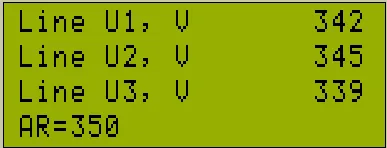
Figure 5.17 – Indicator when displaying the time remaining until ARS
Table 5.13 – Fault codes
| Fault description | Fault mnemonics | Parameter value | Param. addr. | Fault code | Register address |
|---|---|---|---|---|---|
| Maximum phase current | I max | Maximum phase current | 300 | 0 | 901:0 |
| Thermal overload | Thermal over | 301 | 1 | 901:1 | |
| Ground fault (zero sequence current) | Iearth | Zero sequence current | 302 | 2 | 901:2 |
| Excess ratio of negative sequence current to negative sequence voltage | Coef I/U | Coefficient of negative sequence current ×100 | 303 | 3 | 901:3 |
| Negative sequence current | I2 rev | Negative sequence current | 304 | 4 | 901:4 |
| Minimum phase current | I min | 305 | 5 | 901:5 | |
| Delayed start | Long Start | Current | 306 | 6 | 901:6 |
| Rotor blocking | Block Rot | Current | 307 | 7 | 901:7 |
| Upon reaching the temperature threshold of the first transmitter | Temp1 | Temperature in degrees | 308 | 8 | 901:8 |
| Upon reaching the temperature threshold of the second transmitter | Temp2 | Temperature in degrees | 309 | 9 | 901:9 |
| Phase sequence | Phase Sequen | 310 | 10 | 901:10 | |
| External MS (the presence of currents when load relay is disabled) | Contactor | Current | 311 | 11 | 901:11 |
| At minimum line voltage | U min | Voltage | 312 | 12 | 901:12 |
| At maximum line voltage | U max | Voltage | 313 | 13 | 901:13 |
| At phase imbalance | Uimbal | Imbalance | 314 | 14 | 901:14 |
| Minimum insulation resistance of motor winding | Insul Res | Insulation resistance | 315 | 15 | 901:15 |
| Mains minimum frequency | F min | Frequency | 316 | 16 | 902:0 |
| Mains maximum frequency | F max | Frequency | 317 | 17 | 902:1 |
| Fault of remote control channel | Remote Cont | 18 | 902:2 | ||
| Motor emergency shutdown without possibility for restart | Stop nAR | 19 | 902:3 | ||
| Motor emergency shutdown with possibility to restart by simultaneously pressing the buttons UP and DOWN | Stop Motor | 20 | 902:4 | ||
| s.c. of temperature transmitter 1 | Short TempS1 | 21 | 902:5 | ||
| Breakout of temperature transmitter 1 | Break TempS1 | 22 | 902:6 | ||
| s.c. of temperature transmitter 2 | Short TempS2 | 23 | 902:7 | ||
| Breakout of temperature transmitter 2 | Break TempS2 | 24 | 902:8 | ||
| Loss of phase | Break Phase | 25 | 902:9 | ||
| EEPROM destruction | Error EEPROM | 26 | 902:10 | ||
| At analog input “0-20 mA” | Input I | 327 | 27 | 902:11 | |
| At analog input “0-10 V” | Input U | 328 | 28 | 902:12 | |
| Improper calibration | Error CALIB | 29 | 902:13 |
Notes:
-
Occurrence of fault as “EEPROM Error” – the destruction of EEPROM indicates that the data of the programmed parameters (Table 3.6) is damaged. To continue the operation, it is necessary to turn off UBZ and restore the factory settings (5.2.7 – second method).
-
Occurrence of fault as “Error CALIB” – UBZ improper calibration means that the calibration coefficients of the measured data are damaged. The continued operation of UBZ is impossible. Re-calibration of the device is required to be done at the manufacturer factory.
5.6 Emergency Conditions Logbook
Section titled “5.6 Emergency Conditions Logbook”When disabling the load relay in the event of fault, UBZ records in its memory the code of the fault, the value of the parameter on which the fault occurred and time of occurrence.
Number of simultaneously stored fault codes is 50. In case of subsequent faults occur, the fault information is recorded in place of the oldest fault.
To view the log, it is necessary to press button RES/MEM/SEL.
Red LED SETUP will on in flashing mode, and UBZ indicators will display the latest fault (Figure 5.18).
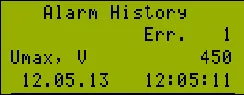
Figure 5.18 – Display in the view mode of the fault logbook
- Line 1 – indication of mode (alarm logbook)
- Line 2 – number of the fault (1 – means the most recent fault)
- Line 3 – mnemonic of the fault as per Table 5.13 and the parameter value at the moment of the fault occurrence
- Line 4 – time and date of the fault
View the fault logbook by pressing the UP or DOWN button.
To exit the view log mode, press the button RES/MEM/SEL or exit will be automatically in 30 seconds after the last pressing of any button.
5.7 Motor control on UBZ front panel
Section titled “5.7 Motor control on UBZ front panel”Depending on the value of the parameter “MotorOp UBZ”, you can control the load relay of UBZ by simultaneously pressing the UP and DOWN buttons:
- “Off” - no reaction;
- “Start” (motor start is enabled) - the load relay will enabled if ARS time has not finished;
- “Stop” (motor emergency shutdown) - the load relay will disabled with the issuance of fault code “Stop nAR”). The restart of the motor is possible only after de-energizing and re-energizing of UBZ device;
- “St<>” (motor start and shutdown is permitted) - the load relay is disabled with issuance of code “Stop Motor”. To enable it, press again UP and DOWN buttons.
5.8 Motor control using analog inputs
Section titled “5.8 Motor control using analog inputs”The motor control algorithms by the analog inputs “0-20 mA” and “0-10 V” are shown in Table 3.6.
After the motor stopping according to emergency level the countdown for ARS will only start after going out the parameter value of the emergency zone.
If after the motor switching off by the alarm level the parameter value is between the levels on and off for the motor, then:
- green LED “Power relay” blinks;
- red LED “FAULT” is off;
- the fault code is displayed on LCD.
6. Maintenance
Section titled “6. Maintenance”6.1 Safety precautions
Section titled “6.1 Safety precautions”Maintenance of the device should be performed by persons admitted to the operation and have the appropriate permission. The recommended frequency of maintenance is every six months.
6.2 Maintenance Procedure
Section titled “6.2 Maintenance Procedure”- check the wires connection reliability, if necessary – clamp with force as specified in Table 3.1;
- check visually the housing integrity;
- if necessary, wipe with cloth the front panel and the device housing.
It is not allowed to clean the device with abrasive materials or organic compounds (alcohol, gasoline, solvents, etc.).
7. Transportation and Storage
Section titled “7. Transportation and Storage”UBZ-304 in the original package of the Manufacturer should be stored indoors with temperature from minus 45 to +60°C and relative humidity of not more than 80% in the absence of vapors harmfully acting on the packaging and materials of the device.
8. Service Life, Shelf Life and Manufacturer Warranty
Section titled “8. Service Life, Shelf Life and Manufacturer Warranty”8.1 The device service life is 10 years. Upon expiration of the service life you should contact the Manufacturer.
8.2 Shelf life is 3 years.
8.3 Warranty period of the device operation is 5 years from the date of sale.
During the warranty period the Manufacturer is responsible for free repair of the device, if the Consumer has complied with the requirements of this Operating Manual.
8.4 Warranty service is performed at the place of purchase or by the Manufacturer of the device.
8.5 Post-warranty service is performed by the Manufacturer at current rates.
8.6 Before sending for repair, the device should be packed in the original or other packaging excluding mechanical damage.
For all questions, please contact the Manufacturer:
“Novatek-Electro” Ltd.
Website: www.novatek-electro.com
Address: 59, Mykhailo Boltenko (Admiral Lazarev) str., Odesa, Ukraine, 65007
Tel: +38 (067) 565 37 68; +38 (050) 359 39 11; +38 (063) 301 30 40