Appendix A: RS-485 Communication Interface
Цей контент ще не доступний вашою мовою.
1 General Information
Section titled “1 General Information”The communication interface is employed to connect the TR-101 device to RS-485 network. The device utilization within RS-485 network allows for the following functions:
- collecting data of measured temperatures within SCADA system;
- setting device parameters with use of configuration software;
- remote control of the channels output relays.
RS-485 as an interface standard has found extensive industrial application; it provides for establishing networks with node count of up to 247 and data transfer at distance of up to 1200 m. With use of duplicators, the number of nodes and the transmission distance can be increased.
All network devices are connected in a serial bus (Figure A1). To maintain the reliable operation of transmitters/receivers and to eliminate interference impact, the communication line ends must be equipped with a terminating resistor of impedance Rсогл = 120 Ohm that is connected immediately to the device terminals (see Figure A1).
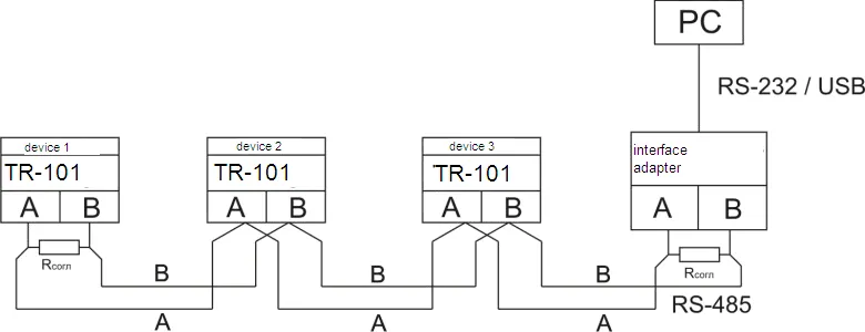
Figure A1 – RS-485 Network Connection Diagram
2 Remote Control for Power Relays
Section titled “2 Remote Control for Power Relays”By installation the value rSA = 2 (Table 7.1) device will be switched to the mode of remote management power relay. Control registers are shown in Table A2.
If the channel working with two level action and labeled to control register value 0 or 1 is possible to switch on or switch off prorated power relay.
If the channel working with PID regulation and labeled to control register value 0 or 100 is possible to manage capacity plug into correspondent relay (pos. 3.2.6.6 of manual).
If the mode “Remote management of power relay” is switched on TR-101 continuous working in usual mode.
Exception is the fact that management of power relay is passed to operator.
3 Data Exchange Adjustment Through Interface RS-485
Section titled “3 Data Exchange Adjustment Through Interface RS-485”Data exchange adjustment is realized by parameters:
| Parameter | Mnemonic | Description |
|---|---|---|
| Switching | rSA | Set switching on (switching off) RS-485 and the mode of remote management |
| Identifier | rSn | Device base address (1…247) |
| Bit rate | rSS | Rate of exchange data online (2400, 4800, 9600 bit/s) |
| Timing | rSL | Time delay of the packet answer 0-99.9 ms |
Device TR-101 has following fixed exchange parameters not shown at the indicator:
- Quantity Stop-bit: 2
- Length of a data word: 8
- Parity check: not
4 Data Exchange Through Interface RS-485
Section titled “4 Data Exchange Through Interface RS-485”4.1 Connection Setup
Section titled “4.1 Connection Setup”Working through interface RS-485 it should be done relevant connection (p. 1 of Appendix A) and set the value of net parameters (p. 3 of Appendix A).
4.2 Network Master
Section titled “4.2 Network Master”For organization data exchange online through interface RS-485 necessary have net Master. The main function of this device is to activate data exchange between sender and recipient. TR-101 may work at Slave mode by ModBus RTU protocol.
4.3 ModBus Protocol
Section titled “4.3 ModBus Protocol”ModBus is the open network protocol that was developed by company Modicon. Protocol description available at website www.modbus.org.
Register addresses of program parameters are shown in Table 7.1 of the manual.
Check list of supported functions (Modbus) is shown in Table A1.
Additional registers and their functions are shown in Table A2.
Supported Modbus Functions
Section titled “Supported Modbus Functions”Table A1 – Supported Modbus Functions
| Function (hex) | Sub-function | Description | Note |
|---|---|---|---|
| 0x03 | — | Receiving value of one or several registers | max. 125 |
| 0x06 | — | Recording one value to the register | — |
| 0x08 | 0x00 | Return query data | Diagnostics |
| 0x08 | 0x01 | Communication options restart | Diagnostics |
| 0x08 | 0x04 | Setting up “listen only” mode | Diagnostics |
Additional Registers
Section titled “Additional Registers”Table A2 – Additional Modbus Registers
Device Identification
Section titled “Device Identification”| Address (dec) | Name | Description | Note |
|---|---|---|---|
| 0 | Device ID (MSB) | TR-101 – 0x0002 | ID |
| 1 | Device ID (LSB) | Firmware version - v53 | Version |
Status Register (Address 2)
Section titled “Status Register (Address 2)”| Bit | Description |
|---|---|
| bit 0 | 0 – no emergency; 1 – Emergency (emergency code in register) |
| bit 1 | 0 – relay of channel 1 is switched off; 1 – relay of channel 1 is switched on |
| bit 2 | 0 – relay of channel 2 is switched off; 1 – relay of channel 2 is switched on |
| bit 3 | 0 – relay of channel 3 is switched off; 1 – relay of channel 3 is switched on |
| bit 4 | 0 – relay of channel 4 is switched off; 1 – relay of channel 4 is switched on |
| bit 5 – bit 15 | reserved |
Emergency Register (Address 3)
Section titled “Emergency Register (Address 3)”| Bit | Description | Display |
|---|---|---|
| bit 0 | 0 – Not emergency; 1 – EEPROM rejection | EEP |
| bit 1 | 0 – Not emergency; 1 – parameter mistake | ErP |
| bit 2 | 0 – Not emergency; 1 – sensor 1 short circuit | FCC |
| bit 3 | 0 – Not emergency; 1 – sensor 2 short circuit | FCC |
| bit 4 | 0 – Not emergency; 1 – sensor 3 short circuit | FCC |
| bit 5 | 0 – Not emergency; 1 – sensor 4 short circuit | FCC |
| bit 6 | 0 – Not emergency; 1 – sensor 1 disconnection | FOC |
| bit 7 | 0 – Not emergency; 1 – sensor 2 disconnection | FOC |
| bit 8 | 0 – Not emergency; 1 – sensor 3 disconnection | FOC |
| bit 9 | 0 – Not emergency; 1 – sensor 4 disconnection | FOC |
| bit 10 – bit 15 | reserved |
Temperature Registers
Section titled “Temperature Registers”| Address (dec) | Name |
|---|---|
| 4 | Sensor temperature 1 |
| 5 | Sensor temperature 2 |
| 6 | Sensor temperature 3 |
| 7 | Sensor temperature 4 |
Relay Control Registers
Section titled “Relay Control Registers”| Address (dec) | Name | When ch = 1 (Two-position) | When ch = 2 (PID) |
|---|---|---|---|
| 8 | Register of relay control 1 | 0 – relay OFF; 1 – relay ON | 0 – capacity 0%; 100 – capacity 100% |
| 9 | Register of relay control 2 | 0 – relay OFF; 1 – relay ON | 0 – capacity 0%; 100 – capacity 100% |
| 10 | Register of relay control 3 | 0 – relay OFF; 1 – relay ON | 0 – capacity 0%; 100 – capacity 100% |
| 11 | Register of relay control 4 | 0 – relay OFF; 1 – relay ON | 0 – capacity 0%; 100 – capacity 100% |
Reserved Registers
Section titled “Reserved Registers”| Address (dec) | Description |
|---|---|
| 12-20 | Registers from 12 to 20 are reserved (equal to zero always) |