EM-486 Operating Manual
Цей контент ще не доступний вашою мовою.
The EM-486 is a MODBUS RTU/ASCII (RS-485) protocol converter manufactured by NOVATEK-ELECTRO LTD.
During operation and maintenance, the regulatory document requirements must be met, namely: Regulations for Operation of Consumer Electrical Installations; Safety Rules for Operation of Consumer Electrical Installations; Occupational Safety when in Operation of Electrical Installations.
Installation, adjustment and maintenance of the device must be performed by qualified personnel having studied this Operating Manual.
In compliance with the requirements of this Operating Manual and regulations the device is safe for use.
This Operating Manual is intended to familiarize you with the device, the requirements for safety, operation and maintenance procedures of the MODBUS RTU/ASCII (RS-485) protocol converter EM-486 (hereinafter referred to as EM-486, device).
The device meets the requirements: EN 60947-1; EN 60947-6-2; EN 55011; EN 61000-4-2.
Harmful substances in amounts exceeding maximum permissible concentrations are not available.
Versions of this device are listed in Appendix A - Versions and Modifications.
Terms and Abbreviations
Section titled “Terms and Abbreviations”- 10Base-T – Ethernet standard for twisted pair communication with the speed of 10Mbit/s
- 100Base-T – Ethernet standard for twisted pair communication with the speed of 100Mbit/s
- 8P8C/RJ45 – unified socket for 10Base-T/100Base-T network connections
- ASCII – table of standard codes for information interchange
- Client – device which is addressing the other devices (server) with a request to perform certain functions
- Display – OLED graphical indicator
- DHCP – Protocol that allows network nodes automatically obtaining the parameters of TCP/IP (IP address)
- Ethernet – standard for packet network communication and transmitting data between units (e.g., PCs)
- FTP – FTP protocol of a file transfer according to the standard TCP/IP
- GPRS – technology of packet transmission of data on mobile communication
- GSM – standard of digital mobile communication
- HTTP – protocol for transferring Web-pages and other data over “client-server” technology
- Indicator – LED element
- Internet – global routing system of units for storing and transferring data
- IP (protocol) – routable protocol for transferring data over Ethernet. Part of TCP/IP and used for Internet
- IP (address) – node address which is unique within a single network, operating over the IP protocol
- IPv4 – four bytes IP-address
- MAC (address) – address used for device authentication during Ethernet transmissions. Usually unique although qualified personnel can change it under certain circumstances
- MAC-48 – six bytes MAC-address
- MODBUS – standard and protocol for packet communication over the “client-server” technology for industrial electronic units
- MODBUS RTU – communication protocol of the unit for byte wise transfer of the package
- MODBUS ASCII – communication protocol of the unit for the transfer of package in the form of ASCII-symbols
- MODBUS TCP – protocol for transferring MODBUS packages under the TCP/IP standard
- NTP – Protocol for clock synchronization at the network nodes with variable delays of transmission
- Package – block of data to be transmitted between devices
- RS-485/EIA-485 – network standard for communicating units over the twisted pair
- Server – unit which performs specific functions at the request of other units
- SMS – standard and technology of transmitting the brief messages via mobile communication
- TCP/IP – standard and a set of protocols for transferring data along the networks with delivery verification
- Twisted pair – pair of insulated conductors inside the cable, which are twisted together in order to reduce the distortion of the transmitted signal
- WEB – system for accessing documents on the server, used in the Internet
- WEB-page – document, file, resource, which is available on the Web-server
- WEB-browser – WEB-server client for accessing the WEB-pages, which is primarily using the HTTP protocol
1 Purpose
Section titled “1 Purpose”1.1 Purpose of the Device
Section titled “1.1 Purpose of the Device”EM-486 provides data collection from connected devices (analog sensors and MODBUS devices), data transfer to the server, access to data (via MODBUS TCP protocol or SMS text messages), event tracking and response (relay control, SMS sending - notifications, writing values to MODBUS devices, saving read values to the log).
EM-486 has:
- Flexible options of connection (via wire or wireless communication, automatic method selection of communicating with a server, automatic or manual selection of GSM provider and communication parameters, resetting of MAC-address and other Ethernet settings)
- Access protection (passwords for configuration or for connection to the MODBUS network, connection only to a specified server with automatic authorization, SMS control password)
- Different modes of data interchange via RS-485 (RTU or ASCII, with checking of parity for even-odds or without checking, wide range of transmitting rate, adjustable delay)
- Programming the collection of data, events, and action for events (see Appendix C - Task Files)
- Programmable outputs for reaction at events and alarms
- Programmable inputs for analog sensors
- Programmable impulse meters for every sensor
- Power output for sensors
- Reserve power supply input
- Service functions (real time clock, firmware updating option)
1.2 Overall and Setting Dimensions
Section titled “1.2 Overall and Setting Dimensions”
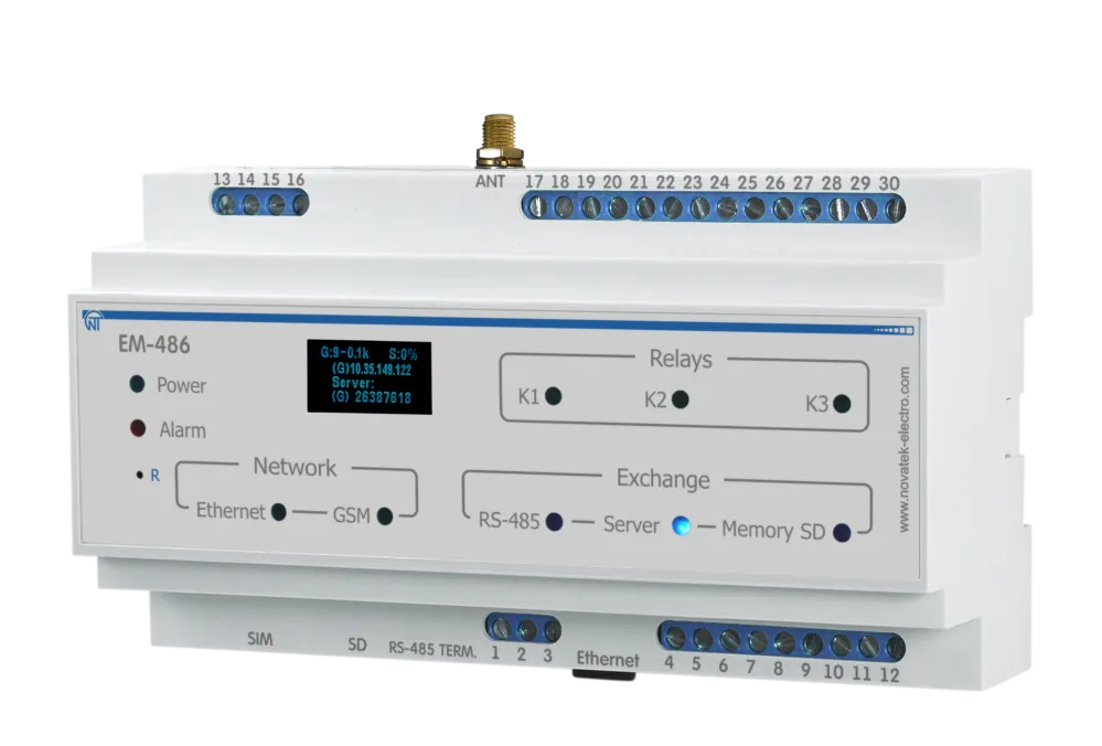
Figure 1.1 – Overall dimensions of the device
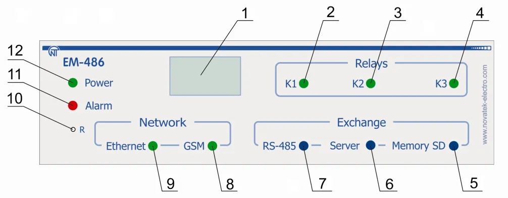
Figure 1.2 – Front panel of EM-486
- Graphic display OLED is designed for indicating the state of the device, connections, communication interface loading and showing the alarm messages.
- Indicator «K1» is lit on when relay K1 is activated.
- Indicator «K2» is lit on when relay K2 is activated.
- Indicator «K3» is lit on when relay K3 is activated.
- Indicator «Memory SD» is lit on when there is a memory card in a special slot, is blinking while transmitting the data to the SD-card.
- Indicator «Server» is lit on when there is a connection with a server for data accumulating, is blinking while data exchange with a server.
- Indicator «RS-485» is lit on when waiting a respond from a device in MODBUS network; is blinking while data exchange via MODBUS network.
- Indicator «GSM» is blinking every 3 seconds when there is a connection via GSM network, is blinking 3 times per second while data exchange via GPRS.
- Indicator «Ethernet» is lit on when there is a connection via Ethernet network; it is blinking while data exchange via network.
- Reset button «R» (is located under the casing and is available for pressing with a help of thin non-conductive object) is designed to restart the device or make factory reset.
- Alarm indicator «Alarm» warns about a recording of the fault when analyzing of the received data.
- LED Indicator «Power» is lit on when power voltage present.
1.3 Operating Conditions
Section titled “1.3 Operating Conditions”EM-486 is designed for operation in the following conditions:
- Ambient temperature: from minus 35 to +55°С
- Atmospheric pressure: from 84 to 106.7 kPa
- Relative air humidity (at temperature of +25°С) 30 … 80%
If the temperature of the device after transportation or storage is different from the temperature of the environment in which its operation is assumed, then before connecting to the mains keep the device in operation conditions for two hours (because on the device elements condensation may be available).
2 Complete Supply Set
Section titled “2 Complete Supply Set”| Item | Quantity |
|---|---|
| EM-486 | 1 pcs. |
| Cable for Ethernet connection | 1 pcs. |
| GSM antenna (SMA M connector, 50 Ω)* | 1 pcs. |
| MicroSD card (2 Gb) | 1 pcs. |
| Operating Manual | 1 pcs. |
| Shipping box | 1 pcs. |
* other types of antennas are delivered in coordination with the buyer
3 Technical Specifications
Section titled “3 Technical Specifications”| Parameter | Value |
|---|---|
| Operating supply voltage, VAC | 230/240 |
| Supply line frequency, Hz | 45 – 65 |
| Data Exchange Interface over the Ethernet network | 10Base-T / 100Base-T |
| Supported Ethernet protocols | UDP, ARP, TCP |
| Data Exchange Interface over wireless network | GSM (850/900/1800/1900) |
| Supported standards of wireless network | SMS, GPRS |
| Integrated servers | MODBUS TCP, HTTP |
| Maximum number of connections over the MODBUS TCP protocol | 4 |
| Data Exchange Interface over the MODBUS network | RS-485 |
| Supported protocols of MODBUS network | MODBUS RTU, MODBUS ASCII |
| Maximal output voltage of driver RS-485, V | 3.3 |
| Short circuit output voltage of driver RS-485 (maximal), mA | 250 |
| Resistance of inbuilt terminator, Ω | 70 – 1000 or deactivated |
| The recommended number of connected devices in MODBUS network: | |
| - at input voltage of receivers on bus RS-485 not more than 0.125 mA | ≤ 256 |
| - at input voltage of receivers on bus RS-485 not more than 1 mA | ≤ 32 |
| Readiness time at power switching on, sec | ≤ 15* |
| Precision measurements of voltage, mV | ≤ 100 |
| Precision measurements of current, µA | ≤ 200 |
| Precision measurements of temperature, °C | ≤ 2 |
| Rated voltage direct current back supply, V | 12 |
| Voltage supply at which operability is maintained: | |
| - alternative current, V | 90 – 265 |
| - direct current, V | 127 – 375 |
| Back supply voltage at which operability is maintained, V | 9 – 16 |
| Power consumption (under pressure), W | ≤ 12 |
| The maximum switched current of output pins, A | 16 |
| Universal inputs | 4 |
| Types of the connected gauges: | gauge with voltage output to 10 V; gauge with current output to 20 mA; «dry contact»; NTC temperature gauge |
| The maximum voltage on the universal input, V | 12 |
| The maximum current through the universal input, mА | 24 |
| The voltage of sensors power output, V | 12 |
| The maximum current of sensors power output, А | 0.1 |
| Programmable relay outputs with switching contacts, pcs. | 3 |
| Commutation service life of output contacts: | |
| - electrical service life under load 16 A (cos φ = 1.0), times | ≥ 50,000 |
| - mechanical service life, times | ≥ 10,000,000 |
| Device purpose | Communication equipment |
| Nominal operation condition | Continuous |
| The protection level | IP 20 |
| Climatic version | NF 3.1 |
| Permissible pollution density | II |
| Overvoltage category | II |
| Protection class against electrical shock | II |
| Rated insulation voltage, V | 450 |
| Rated impulse withstand voltage, kV | 2.5 |
| Cross section of wires of connection terminals, mm² | 0.5 – 3 |
| Maximal tightening torque of terminals external screws, N·m | 0.4 |
| Weight, kg | ≤ 0.750 |
| Overall dimensions, H×B×L, mm | 157 × 99 × 56 |
| Standard 35 mm DIN rail mounting | |
| Housing material | Self-extinguishing plastic |
* Connections on the Ethernet networks/Internet can take more time
The device remains operational capability in any position in space.
4 Design
Section titled “4 Design”EM-486 provides control for MODBUS in RS-485 network via Ethernet interfaces or GPRS, or via the SMS. The device also allows to read data from devices by MODBUS or from connected sensors.
The processor supports connection to the accumulating data cloud server via Ethernet network with a help of microchip of physical interface of Ethernet (or via GPRS with a help of inbuilt GSM-modem, if connection via Ethernet is not available). In addition, EM-486 can be connected via MODBUS TCP Protocol to exchange data with MODBUS devices, or with the device. The controller receives and processes SMS with a password and command read/write for MODBUS devices.
When inserting a memory card, the device reads the internal memory for operational logic – program for data collection and tracking of events. The program runs in the background mode. The collected data can be saved to a memory card in tabular or binary files.
The device stores in the built-in memory network settings, input and output parameters, security parameters, and action logic.
5 The Intended Use
Section titled “5 The Intended Use”5.1 Preparation for Operation
Section titled “5.1 Preparation for Operation”5.1.1 Preparation for Connection
Section titled “5.1.1 Preparation for Connection”- Unpack and check the device for damage after transportation; in case of such damages detection, contact the supplier or manufacturer;
- Carefully study the Operating Manual (pay special attention to the connection diagram to power the device);
- If you have any questions regarding the installation of the device, please contact the manufacturer by telephone number indicated at the end of this Operating Manual.
5.1.2 General Instructions
Section titled “5.1.2 General Instructions”To ensure the reliability of electrical connections you should use flexible (stranded) wires with insulation for voltage of not less than 450 V, the ends of which it is necessary to be stripped of insulation for 5±0.5 mm and tightened with bootlaces. Recommended cable cross section for connection is not less 1 mm².
EM-486 connection to RS-485 bus is made by cable of twisted pair type Cat.1 or higher category. It is recommended to use the shielded cable, in this case it should be grounded (in accordance with «ANSI/TIA/EIA-485-A-1998» recommendations).

Figure 5.1 – The Device connection diagram
- F1 – fuse (fuse element), for current of 0.25 А
- F2 – fuse (fuse element), for current of 2.5 А
- F3 – fuse (fuse element), for current of 0.25 А
- Contact “A” is designed for transferring non-inverted signal
- Contact “B” is used for the inverted signal
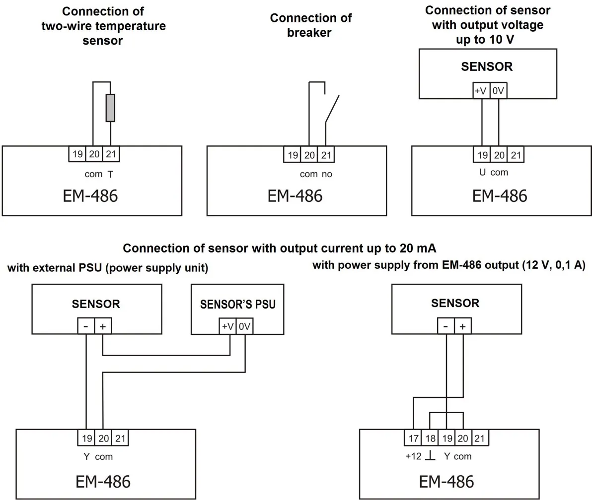
Figure 5.2 – Sensors connection diagram
In case of connection to Ethernet it is necessary to use a cable in a set, or the “twisted pair cable” cable of the Cat.5e category with the 8P8C (RJ-45) tip. Wires fastening should exclude mechanical damage, twisting and insulation abrasion of wires.
For reliable contact it is necessary to perform tightening of screws of removable terminal block with the force specified in Table 3.1.
When reducing the tightening torque, the junction point is heated, terminal block may be melted and wire can burn. If you increase the tightening torque, it is possible to have thread failure of terminal block screws or the compression of the connected wires.
To improve operational properties of the device it is recommended to install the F1-F3 fuse (fuse element), or the equivalent in power supply circuit for EM-486 (see Fig 5.1).
5.1.3 EM-486 Switching On
Section titled “5.1.3 EM-486 Switching On”-
The device is switched according to the diagram, see Fig 5.1.
-
Switch the cable connection with MODBUS network (twisted pair cable of Cat.1 or higher) to the “RS-485” socket and MODBUS network (or directly to the device with RS-485 interface).
- If EM-486 is connected to the middle of bus RS-485, or if the bus has external terminals at the ends – set the over switches «RS-485 Term.», located next to slot «RS-485», in position OFF.
- If EM-486 is connected at one of the ends of bus RS-485, without a terminal – set the over switches «RS-485 Term», located next to the slot «RS-485», in accordance with wave resistance of bus cable, using the Table 5.1.
Table 5.1 – Resistance of integrated terminator of bus RS-485
| № | Resistance, Ω | Switch Position | № | Resistance, Ω | Switch Position |
|---|---|---|---|---|---|
| 1 | Deactivated | ▄ ▄ ▄ ▄ ▄ | 13 | 132 | ▀ ▄ ▄ ▀ ▄ |
| 2 | 1000 | ▄ ▄ ▄ ▄ ▀ | 14 | 120* | ▀ ▀ ▄ ▄ ▄ |
| 3 | 390 | ▄ ▄ ▄ ▀ ▄ | 15 | 118 | ▄ ▀ ▀ ▀ ▄ |
| 4 | 300 | ▄ ▀ ▄ ▄ ▄ | 16 | 117 | ▀ ▄ ▄ ▀ ▀ |
| 5 | 280 | ▄ ▄ ▄ ▀ ▀ | 17 | 107 | ▀ ▀ ▄ ▄ ▀ |
| 6 | 230 | ▄ ▀ ▄ ▄ ▀ | 18 | 106 | ▄ ▀ ▀ ▀ ▀ |
| 7 | 200 | ▀ ▄ ▄ ▄ ▄ | 19 | 99 | ▀ ▄ ▀ ▀ ▄ |
| 8 | 195 | ▄ ▄ ▀ ▀ ▄ | 20 | 92 | ▀ ▀ ▀ ▄ ▄ |
| 9 | 170 | ▄ ▀ ▀ ▄ ▄ | 21 | 90 | ▀ ▄ ▀ ▀ ▀ |
| 10 | 167 | ▀ ▄ ▄ ▄ ▀ | 22 | 84 | ▀ ▀ ▀ ▄ ▀ |
| 11 | 163 | ▄ ▄ ▀ ▀ ▀ | 23 | 74 | ▀ ▀ ▀ ▀ ▄ |
| 12 | 145 | ▄ ▀ ▄ ▀ ▀ | 24 | 69 | ▀ ▀ ▀ ▀ ▀ |
* – is recommended for cable Cat. 3
-
If EM-486 should be connected to Internet via wire line, to local network or directly to PC – connect the Ethernet communication cable to the slot «Ethernet» and to Ethernet network. The details of connection depending on the type of wire line are resulted in Appendix B - Connections.
-
In case of sensors connection to EM-486 universal inputs «IN». The ways of connection of different types are provided in figure 5.2.
-
In case of controlled elements connection to the outputs of programmable relays of the device «K».
-
To connect a power supply to the socket “230 V”. If necessary, to connect a source of back supply to the power connector “12 V”.
-
If EM-486 should be connected to Internet via wireless connection – insert SIM-card of mobile communication operator in SIM slot; connect the antenna to the slot “ANT” (terminal SMA F).
5.2 Use of the EM-486
Section titled “5.2 Use of the EM-486”5.2.1 General Information
Section titled “5.2.1 General Information”After power supply is provided to the device, all indicators light up, except for «Ethernet» and «GSM», and the device performs the initialization. After this for 2 seconds the indicators, except for indicator of power, light down, and the device proceeds to start the interface of networks connection. At that the display shows general information about the device.
EM-486© 2023 Novatek-Electro FW - Version 43Figure 5.3 – Showing the general information about the device on the display
The start up can take up to 15 seconds, depending on the settings and quality of connection.
Afterwards the device proceeds with performing the user set program of inquiry for sensors and MODBUS devices.
The device provides and supports the connection to Ethernet/GSM networks.
- When the indicator Ethernet lights up means that connection to a network is executed successfully. The blinking indicator Ethernet means data transmitting in the network.
- If the indicator GSM is blinking one time every three seconds that means the connection to the GSM network is successfully made. If “GSM” LED blinks three times per second, it means enabling the data transmission via GPRS.
The display shows the load of the I/O interfaces, the GSM signal strength and the IP address used:
E: 5.2к S: 15%(E) 10.0.0.1G: 7-0.3к S: 15%(G) 87.1.1.1Figure 5.4 – Showing the state of connections on the display
«E: 5.2к»- rate of transmitting via Ethernet 5.2 kB/s«G: 7-0.3к»- the level of GSM signal is 70%, rate of transmitting via GSM GPRS is 0.3 kB/s«S: 15%»- Loading of RS-485 is 15%«(E): 10.0.0.1»- connection to the local network with the address 10.0.0.1«(G): 87.1.1.1»- wireless Internet access with the address 87.1.1.1
5.2.2 Modes of Operation
Section titled “5.2.2 Modes of Operation”5.2.2.1 Connection to Server
Section titled “5.2.2.1 Connection to Server”EM-486 provides and supports connection to the server specified in the device settings. The light up indicator Server means that the connection to server was successfully made. The blinking indicator Server means that there is a data exchange with the server. The data interchange with server is made via one of two protocols: modified MODBUS TCP and MODBUS TCP for reverse connection.
5.2.2.2 Monitoring of Sensors and Devices Connected via RS-485
Section titled “5.2.2.2 Monitoring of Sensors and Devices Connected via RS-485”Controller inquires the registers of MODBUS devices, which are connected via RS-485 on requests from the server. EM-486 measures the reading of connected sensors. The taken readings can be resulted in appropriate scale (according the type of sensor and the settings of the device). The resulted values are shown on the display in the appropriate view:
1: - - - 3: 25C2: - - - 4: 0.02 АFigure 5.5 – Showing the state of inputs on the display (sensors 1 and 2 are disconnected, a sensor of temperature 3 – 25°C, a sensor of current 4 – 0.02 А)
The server requests can contain MODBUS EM-486 registers for reading sensor readings, load relay status, current time, etc.
5.2.2.3 Access to MODBUS Network via MODBUS TCP Interface
Section titled “5.2.2.3 Access to MODBUS Network via MODBUS TCP Interface”EM-486 performs the function of MODBUS gateway and waits for network connection via MODBUS TCP protocol to port 502. The MODBUS TCP connection port can be changed by the user. Connection to PC can be made by any programs – MODBUS TCP clients. The client version for Windows software is available for download on the manufacturer’s web-site (http://novatek-electro.com/en/software.html).
At inquiry for client connection to MODBUS TCP port, the device checks a list of available connections. If all connections are already engaged, the connection is cancelled otherwise the device adds it into its internal list of service clients (not more than specified number of clients).
At connection with a client the device waits for MODBUS-inquiry from the client. In RS-485 slave mode, RS-485 queries are also received from the MODBUS master.
After receiving the inquiry from the client, the device analyses the inquiry and, depending on code of inquired function and actual rights of the client, processes and blocks it. At blocking the inquiry EM-486 can generate and send to the client the specified by the user code of MODBUS exception (by default – code 1). The client’s authority level is defined by the entered passwords.
If the inquiry is addressed to EM-486, the device does not re-direct it, but processes it and send the reply to the client. In RS-485 master mode, the inquiries to the other devices are re-directed in MODBUS network, and the reply is waited from the device in MODBUS network – at that event the indicator RS-485 lights on. If the data is received or if the time is out the indicator RS-485 lights down.
In redirection mode to a remote server, if communication with remote MODBUS TCP server is set in Ethernet network or GSM, the queries to other devices are also sent to this server, and a response is expected from it.
If the query could not be redirected (for example, in the RS-485 slave mode, if the connection to the remote MODBUS TCP server was terminated), the EM-486 can generate and send the MODBUS user-defined exclusion code to the client (default code is 10).
If there is no reply, EM-486 can generate and send to the client the specified by the user code of MODBUS exception (by default – code 11).
If there is a reply received on inquiry, EM-486 sends it to the client who had sent this inquiry.
5.2.2.4 Access to MODBUS Network via SMS
Section titled “5.2.2.4 Access to MODBUS Network via SMS”If there is GSM-connection established, EM-486 receives incoming SMS. All incoming SMS begins with a password. If the password does not match the one specified in settings, SMS is not operated and the reply SMS is not being sent back.
After password through a gap is followed command. The command consists of:
- access symbol (“R” for reading by MODBUS functions with codes from 1 to 4, “W” for writing by MODBUS functions with codes 5 – 6)
- address (identification) of the device in MODBUS network
- resource symbol (“H” for the most frequently used MODBUS registers for storing values, “I” for input registers, “D” for discrete inputs, “C” for flags)
- addresses of resource (register)
For the writing function additionally after the space there is the value for locating by address.
Examples:
- SMS message
«abc r1h100»will cause sending the request for reading the register 100 of device 1 (in case when the password for reading via SMS is specified as “abc” in the settings) - SMS message
«stanc12 w2h174 5000»is for writing the value 5000 in register 174 of device 2 (in case when the password for writing via SMS is specified as “stanc12” in the settings)
If the command format is correct, the device generates a MODBUS query, which is further processed in the same way as queries from the other users (see 5.2.2.3).
For the correct response to the query, EM-486 forms the reply SMS. SMS begins with a command prior received from the user. After the command and space there should be the value of register specified in the command (both at reading and writing). The presence of register value in SMS is as confirmation of successful fulfillment of command. For example, SMS «r1h100 2200» means that the value 2200 of register 100 by command for reading from the device 1 has been read.
If the response to the query is MODBUS exception code, EM-486 forms SMS with a reply about exception. SMS begins with a command previously received from the user. After command and space there should be a warning about exception. The warning consists of a line «EXC.» and a number of exceptions. After the warning and space there can be the text description of exception with this number. For example, the message «r3h873 EXC.2 ILLEGAL DATA ADDRESS» means that for the device 3, a register with address 873 is not executable for reading (or is not available).
Table 5.2 – The standard MODBUS exception codes
| Code | Exception | Description |
|---|---|---|
| 1 | Illegal function | The received code cannot be processed |
| 2 | Illegal data address | The data address specified in the inquiry is not available |
| 3 | Illegal data value | The value in the inquiry is not acceptable |
| 4 | Device failure | Non-recoverable failure happened when addressee tried to execute the inquired action |
| 5 | Acknowledge | The addressee has received the inquiry and is processing it but this action takes a lot of time |
| 6 | Device busy | The addressee is processing the command. The client can resend the message later |
| 8 | Memory parity error | The parity error was detected when addressee was trying to read the extended memory |
| 10 | Gateway paths not available | The gateway cannot redirect the inquiry because there is no path (connection) to the addressee |
| 11 | Target device failed to respond to gateway | The gateway has not received a reply on redirected inquiry because the addressee had not replied on time |
5.2.2.5 Data Collection and Event Tracking
Section titled “5.2.2.5 Data Collection and Event Tracking”When the operational logic program is loaded into the internal memory, the device with the specified interval, reads the specified registers (of connected devices or EM-486), and then performs the specified transformations and the evaluation of the received data. The results can be: writing the read values to the log on the memory card, sending SMS, turning on/off of the relay, the entry in the specified register (of connected device or EM-486).
The program downloading to the internal memory is performed from the memory card. The procedure for preparing and loading the program into the device is described in Appendix C - Task Files.
5.2.2.6 Programmable Relays
Section titled “5.2.2.6 Programmable Relays”The relay outputs can switch between two states: normal and active. By default, in the normal state the relay is off, in the active state it is on, and when power is applied all relays remain in the normal (off) state. The normal state of individual relays can be inverted in the settings, such relays will be on when the power is applied. The state of the inverted relay is indicated by a special indication: in the normal state the relay indicator flashes briefly once per second, in the active state - briefly goes out once per second.
Relays can be operated by commands in two modes:
- Automatically, relays are switched by commands in the action logic program
- Manually, relays are switched by commands via MODBUS TCP
When powered up, the relays remain in automatic control mode until the first manual command to this relay via MODBUS TCP. After that, the relays remain in manual mode until the MODBUS TCP command to return to automatic mode, or until the device is restarted.
5.3 Settings
Section titled “5.3 Settings”5.3.1 General Information
Section titled “5.3.1 General Information”The connection settings of EM-486 is made via HTTP protocol or via MODBUS TCP protocol and serves for specifying the main parameters needed for the device operation: types of connected sensors, exchange parameters via RS-485, parameters of address in Ethernet network (if Ethernet is used) and server address to which EM-486 is connected automatically.
The adjustable parameters are described in Appendix D - Registers. The parameters remain saved after the power cut off.
The device setting can be made by two methods:
- Via WEB-interface, as provided in item 5.3.3
- Via MODBUS-interface as described in item 5.3.4
Safety remove of the memory card, restarting device or reset of settings to factory values is executed by means of the R button available through a hole on a front panel. The button is pressed with a thin non-conductive object.
The reset of the device to factory settings:
- Press and hold the reset button R for not less than 8 seconds
- After 2 seconds of holding the indicator Alarm will light on
- After 8 seconds of holding the device will restart, the indicators will blink one time
- Then release the button R
To restart the device with saving of the user’s settings:
- Press and hold the reset button R during time from 2 to 8 seconds
- When the indicator Alarm lights on, release the button R
To display information about connections or safely remove of the memory card:
- Press and release the reset button “R”, the display shows information about connections, the indicator “Memory SD” will go out
- Remove the memory card if necessary
5.3.2 Parameters of EM-486
Section titled “5.3.2 Parameters of EM-486”The format of parameters presentation in MODBUS registers is described in the Appendix D - Registers.
5.3.3 Configuring EM-486 through WEB Interface
Section titled “5.3.3 Configuring EM-486 through WEB Interface”WEB-browser is used for setting via WEB-interface.
- Write the device IP-address in your browser (to display address on the display of the device see section 5.3.1) and proceed to the specified address.
-
Select “Parameters” for setup of parameters. Password request shall appear before granting access to setup mode (factory setting 11111).
-
Enter password and press Enter. If the password is correct, you shall be granted access to the setup mode. You will see the settings page. If the password is incorrect, the password request shall be displayed once again.
-
Settings on the settings page are grouped by types and are divided into tabs. Non-configurable settings and measurements are available in the tab “State”. Settings on other tabs are listed in Appendix D - Registers.
-
Click Save after making changes to the settings. This will check all the changed parameters. If no errors is detected, new parameters will be stored in the memory (new settings will take effect after the following application of settings or restart of the device). In case of any errors detected upon clicking the Save button, none of the parameters is saved, while the names of erroneous parameters are highlighted in red.
-
To apply the settings without restarting the device, you should click “Apply” at the bottom of the page. The entered settings will be checked. If the values of the parameters have not errors, the parameters will be stored in the memory of EM-486 and will come into force. Only MODBUS parameters, inputs, outputs and user-defined parameters can be applied without restarting.
-
To set the clock on the tab “Time”, press “Set” button.
-
Click “Restore defaults” to restore the default value of parameters.
-
Click “Reset” to stop all connections and interrupt all receive/transmit operations, with the following restart of the device. In case of any changes to the parameters, either introduced or stored in the memory, these changes shall be implemented.
- Clicking the “Leave” button will close the setup mode and a password request appears once again.
5.3.4 Configuring EM-486 through MODBUS Interface
Section titled “5.3.4 Configuring EM-486 through MODBUS Interface”Setting via MODBUS-interface shall be provided if the device is connected over the MODBUS-client, which is supporting the MODBUS TCP protocol. The connection is established using its IP-address (for display of the address on the device display see the item 5.3.1) with the indication of MODBUS-identifier (factory setting - 111).
Write the password string into the password input register (see Appendix D - Registers) before setting parameters. Factory set password – is 11111, i.e. write 49 - ASCII-code for one to record the factory set password to registers 100 – 104 (see Appendix B - Connections). If the password is correct, the mode register takes the value of 1 – setup mode.
The instruction registers, as well as registers for the collection of MODBUS customizable parameters are available for writing in the setup mode. When the required value is written to the registers of customizable parameters, write 2 (instruction for “Saving”) in the instruction register. The accuracy of values for the stored parameters can be checked by comparing the collections of customizable parameters and saved parameters. If collections are the same, new values and settings shall be accepted and saved.
To apply the settings without restarting the device you should write into the parameter of the control command the value “4” – command “Save and apply”. Only MODBUS, inputs, outputs and user parameters can be applied without restarting the device. The correctness of the saved parameter values can be checked by comparing the sets of configurable parameters and current settings. If the sets match, then the new settings are accepted and saved.
To cancel the changes in the parameters before saving them, you should write “9” value to control command parameter - the “Cancel” command. In this case, the configurable parameters take the values stored.
To reset the saved parameters to factory settings, write 444 (instruction for “Restoring to factory”) in the instruction register.
Can be restart the device for the saved settings to take effect. To restart via MODBUS interface, write 1 (instruction for “Restarting”) in the instruction register.
To exit the setup mode, write 0 instead of any character in password input register. This will clear all the password input registers and instruction register (turn the values to 0).
6 Maintenance
Section titled “6 Maintenance”Maintenance of the device should be performed by persons admitted to the operation and have the appropriate permission.
The recommended frequency of maintenance is every six months.
Maintenance Procedure:
- Check the wires connection reliability, if necessary – clamp with force as specified in Table 3.1
- Check visually the housing integrity
- If necessary, wipe with cloth the front panel and the device housing
7 Service Life and Warranty
Section titled “7 Service Life and Warranty”- Service life – 10 years. Contact manufacturer upon the expiry of the service life.
- Guaranteed storage life – 3 years.
- Warranty period of the device operation is 5 years from the date of sale.
During the warranty period the Manufacturer is responsible for free repair of the device, if the Consumer has complied with the requirements of this Operating Manual.
Warranty service is performed at the place of purchase or by the Manufacturer of the device.
Post-warranty service is performed by the Manufacturer at current rates.
Before sending for repair, the device should be packed in the original or other packaging excluding mechanical damage.
8 Transportation and Storage
Section titled “8 Transportation and Storage”EM-486 in the shipping box should be stored indoors at a temperature of -45 to +60°C and relative humidity of no more than 80% with no vapors available in the air, capable of producing harmful effect on the shipping box and device materials.
Please, when returning the device or sending it for warranty or post warranty repair, in reclamation data line in passport, explain in details the reason of returning.
Contact Information
Section titled “Contact Information”Please contact the manufacturer should you have any questions.
“Novatek-Electro” Ltd.
- Website: www.novatek-electro.com
- Address: 59, Mykhailo Boltenko (Admiral Lazarev) str., Odesa, Ukraine, 65007
- Tel: +38 (067) 565 37 68; +38 (050) 359 39 11; +38 (063) 301 30 40