UBZ-302M Operating Manual
Цей контент ще не доступний вашою мовою.
«NOVATEK-ELECTRO» Ltd
Intelligent industrial electronics
ELECTRIC MOTORS UNIVERSAL PROTECTION DEVICE
Section titled “ELECTRIC MOTORS UNIVERSAL PROTECTION DEVICE”UBZ-302M
Section titled “UBZ-302M”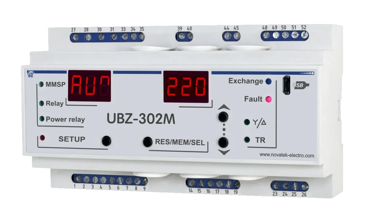
Operating MANUAL
Quality control system on the development and production complies with requirements ISO 9001:2015
Dear customer,
Company NOVATEK-ELECTRO LTD. thanks you for purchasing our devices.
You will be able to use properly the device after carefully studying the Operating Manual.
Keep the Operating Manual throughout the service life of the device.
UKRAINE, Odesa — www.novatek-electro.com
1 Description and Design
Section titled “1 Description and Design”1.1 Purpose
Section titled “1.1 Purpose”1.1.1 General Information
Section titled “1.1.1 General Information”UBZ-302M Electric Motor Universal Protection Device (UBZ-302M) is designed for continuous monitoring of the circuit voltage parameters, the RMS values of phase/line currents of three-phase electric equipment, and the electric motor insulation resistance values.
UBZ-302M is a functional analog of UBZ-302. But in UBZ-302M, the USB interface is used for communication with PC instead of RS-232.
UBZ-302M is designed for protection of asynchronous induction motors ranging from 2.5 kW to 30 kW that use integrated current transformers, including in circuits with insulated neutral.
UBZ-302M provides for electric motor protection in case of:
- poor quality supply voltage (unacceptable voltage surges, phase loss, incorrect phase sequence and phase coincidence, phase/line voltage imbalance);
- mechanical overloads (symmetrical phase/line current overload);
- exceeding the negative sequence current threshold;
- phase current imbalance without overload, induced by the insulation fault inside the motor and/or the lead cable (the current imbalance factor is compared to the voltage imbalance factor using negative sequence);
- loss of motor torque (“dry stroke” for pumps) – protection based on the minimal starting and/or operating current;
- delayed motor start or rotor locking;
- abnormally low insulation level between the fixed coil and frame (testing before motor startup);
- ground fault of the stator coil during operation - protection against ground leakage current;
- motor thermal overload;
- coil overheating (measuring the coil temperature with integrated temperature sensors, or the body temperature with external temperature sensors).
For each protection type, automatic reclosing (ARC) can be enabled or disabled.
The device provides for electric equipment protection by means of controlling a magnetic starter (contactor) coil.
The device detects the presence of load currents when the load relay is open (when the load relay is open and the functional relay is in the star-delta mode). In this case the Unit initiates the alarm of external Magnetic Starter (further in text as MS), which starts the engine, until the unit or the control of engine currents are switched off while the load relay is deactivated.
UBZ-302M provides for electric motor control through the following interfaces:
- two analogue inputs – “0-20 mA” and “0-10 V”;
- remote control channels (USB and RS-485 interfaces);
- buttons on the front panel of the UBZ-302M.
Communication:
- control and parameter transfer via the RS-485 interface using the MODBUS protocol;
- control and parameter transfer via the USB interface.
To use UBZ-302M with a PC, you can use the “UBZ-302 Control Panel” software, available from the website of NOVATEК-ELECTRO www.novatek-electro.com, there is software in division.
The UBZ-302M Control Panel software is designed for monitoring the status of UBZ-302M devices and retrieving data from them via the USB or RS-485 interface. The application allows saving (loading) various UBZ-302M settings, collecting data and saving it for further analysis. Saved data can be viewed on a diagram for parameter comparison.
The software’s graphic user interface allows viewing the current status of various UBZ-302M parameters in real-time. The flexible interface design allows any degree of customization.
1.1.2 Changes in the UBZ-302M Specifications and Operation Depending on the Software Version
Section titled “1.1.2 Changes in the UBZ-302M Specifications and Operation Depending on the Software Version”There are no changes in the program version 22.
1.1.3 Limitations of UBZ-302M Application and Correct Choice of Parameters
Section titled “1.1.3 Limitations of UBZ-302M Application and Correct Choice of Parameters”When using internal current transformers, UBZ-302M cannot be used to protect motors with wattage over 30 kW.
When measuring motor currents of 63 A to 300 A, the measurement error does not exceed 5%, while at currents over 320 A, the current transformer core becomes saturated, and the measurement error increases rapidly. Regardless of the actual current value, the current measured by UBZ-302M will not exceed 400 A. Setting up certain programmable parameters (maximum current protection, delayed start and rotor locking, thermal overload) without regard to the saturation of current transformers will make protection tripping impossible.
For example, at ind=50 (rated current), i⁼P=0 (independent delay current protection), i⁼5=9 (overcurrent protection tripping ratio), the overcurrent protection should trip at 450 А. Due to the transformer saturation, the measured value of current will not exceed 380-400 A, even in case of a short circuit in the coil and currents of over 1000 A, and, therefore, UBZ-302M will not de-energize the motor. In this case (ind=50), the user should set the overcurrent tripping ratio at a value not exceeding 6.
The rated current of external standard current transformers must be equal or higher than the rated current of the motor.
1.1.4 List of Abbreviations
Section titled “1.1.4 List of Abbreviations”- ARC – automatic reclosing of the output contacts (autoreclosing).
- MS – magnetic starter.
- PC – personal computer.
- CT – current transformer.
- MMSP – mode with minimal number of setting parameters.
- Itt – rated current of CT (specified when external CT are used. For example, if CT is type Т-0.66 300/5, then Itt is 300 A).
- In – rated motor current. Usually, the current value shown on the motor plate, but a different current value may be set subject to specific operating conditions.
1.2 Technical Specifications
Section titled “1.2 Technical Specifications”1.2.1 Main Technical Specifications
Section titled “1.2.1 Main Technical Specifications”An overview is provided in Table 1.1.
The main technical specifications are provided in Table 1.2.
The parameters of the integrated relay output terminals are shown in Table 1.3.
Table 1.1 - General Information
| Item | Value |
|---|---|
| Purpose of device | Control and distribution equipment. Asynchronous motor protection control |
| Assembly (mounting) type | mounted on standard 35 mm DIN bar |
| Protection degree: - device | IP 40 |
| Protection degree: - terminal block | IP 20 |
| Climate zone category | NF 3.1 (moderate, indoors) |
| Operating temperature range, °С | from -35 to +55 |
| Storage temperature, °С | from -50 to +60 |
| Pollution degree | III |
| Overvoltage category | III |
| Diameter of adapters on terminals, mm² | 0.5-2 |
| Maximum torque of terminal screws, N*m | 0.4 |
Table 1.2 – Main Technical Specifications
| Parameter | Value |
|---|---|
| Rated supply voltage: three-phase | 400/415 V |
| Mains frequency, Hz | 48 - 62 |
| Rated currents range (when using integrated current transformers), A | 5-63 |
| Voltage hysteresis, (phase/line), V | 10/17 |
| Thermal hysteresis, % of accumulated heat at shutdown | 33 |
| Current tripping threshold detection accuracy, % of rated current, ≤ | 2 |
| Voltage tripping threshold detection accuracy, V, at least | 3 |
| Voltage based phase imbalance detection accuracy, V, at least | 3 |
| Minimum operational voltage: single-phase voltage power supply, with connected neutral wire, V, at least | 180 |
| Minimum operational voltage: three-phase power supply voltage, V, no more than | 450 |
| Temperature sensor resolution, °С | 1 |
| Power consumption (under load), VA, no more than | 5.0 |
| Weight, kg, no more than | 0.5 |
Main outputs:
- load relay – two groups of changeover contacts for motor starter control – 8 A, 250 V at cos φ=1;
- functional relay – one group of changeover contacts - 16 A, 250 V at cos φ=1 (relay function assigned by the user)
Analog inputs:
- two analog inputs for temperature sensors (type Pt100, Ni100, Ni120)
- analog input for sensor with 0-10 V output
- analog input for sensor with 4 mA (0mA) – 20 mA output
- three analog inputs for standard CT with 5 A output (type T-0.66 or similar)
- input for differential current transformer (zero sequence transformer)
Dimensions: nine S type modules. Mounting – on a standard 35 mm DIN bar. The device retains its operability in any position in space.
Table 1.3 – Characteristics of output terminals of integrated relays
| Relay | Operation mode | Max. current at U~250 V | N of tripping x 1000 | Max. commutated power | Max. additional alternating voltage | Max. current at Uconst=30 V (N of tripping) |
|---|---|---|---|---|---|---|
| functional relay | cos φ = 0.4 | 5 A | 100 | 4000 VA | 440/300 V | 3 A |
| functional relay | cos φ = 1.0 | 16 A | 100 | 4000 VA | 440/300 V | 3 A |
| load relay | cos φ = 0.4 | 2 A | 100 | 1000 VA | 460 V | 3 A (50000) |
| load relay | сos φ = 1.0 | 8 A | 100 | 1000 VA | 460 V | 3 A (50000) |
UBZ-302M complies with requirements: EN 60947-1; EN 60947-6-2; EN 55011; EN 61000-4-2
Hazardous substances in excess of maximum allowable concentration – absent.
1.2.2 Measured and Calculated Parameters
Section titled “1.2.2 Measured and Calculated Parameters”Measured and calculated parameters output to the display unit.
Measured and displayed parameters, their effective range limits and tolerances are shown in Table 1.4 of Appendix C: Modbus Communication.
1.2.3 Programmable Parameters
Section titled “1.2.3 Programmable Parameters”Programmable parameters and their variability ranges are shown in Table 1.5 of Appendix C: Modbus Communication.
1.2.4 UBZ-302M controls and dimensions
Section titled “1.2.4 UBZ-302M controls and dimensions”UBZ-302M controls and dimensions are shown in Figure 1.1.
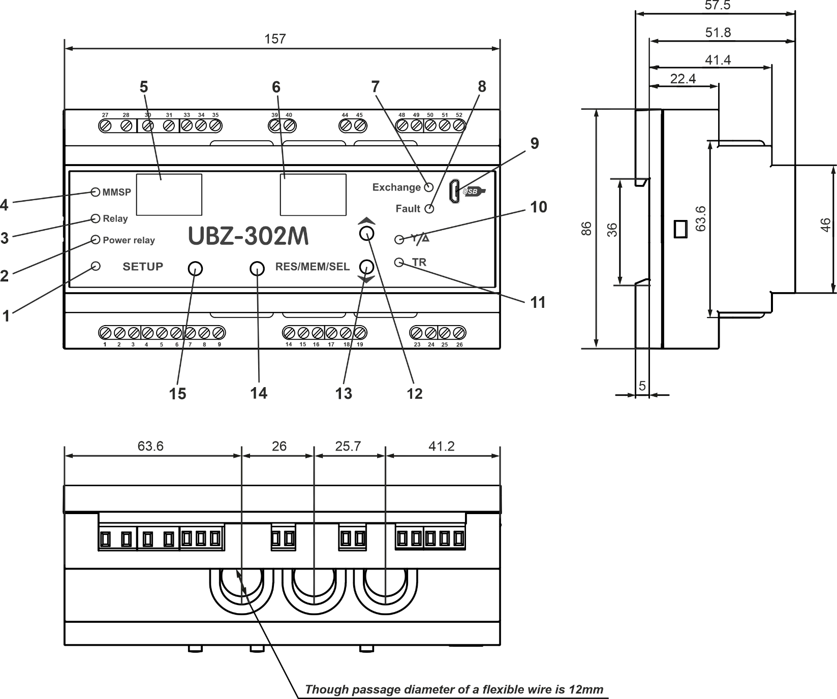
Figure 1.1 – UBZ-302M dimensions
Controls description:
- SETUP - red LED, lit when UBZ-302M in the parameter setting mode;
- Power relay – green LED, lit when the load relay is closed;
- Functional relay – green LED, lit when the functional relay is closed;
- MMSP – green LED – lit when the UBZ-302M is working in the MMSP mode;
- Three-digit parameter mnemonic indicator:
- point in the lowest digit is lit when the UBZ-302M is in the engineer setting mode;
- point in the middle digit is lit when the setting parameter value is protected with the engineer password;
- point in the highest digit is lit when the setting parameter is not included in the MMSP list;
- Three-digit parameter value indicator;
- EXCHANGE – blue LED – lit during data exchange with PC;
- FAULT – red LED:
- when load relay is open, the LED is lit when UBZ-302M is in a state of fault (blinking if ARC is allowed after fault);
- when load relay is closed, the LED blinks when the motor is in a state of overcurrent or temperature overload, but the load relay opening time has not come yet;
- USB outlet for connecting the UBZ-302M to PC via USB;
- Y/∆ – green LED – lit when the UBZ-302M functional relay is in the star-triangle mode (p. 2.4.3);
- TR – green LED – lit when the UBZ-302M functional relay is in the time relay mode;
- Button UP – scroll through displayed parameters in parameter read mode, and scroll through the menu in parameter setting mode;
- Button DOWN - scroll through indicated parameters in parameter read mode, and scroll through the menu in parameter setting mode;
- RES/MEM/SEL – write parameters in setting mode, switch between groups of displayed parameters in parameter read mode, reset;
- Button SETUP – enter parameter setting mode.
1.2.5 Protection Functions
Section titled “1.2.5 Protection Functions”1.2.5.1 Protection Types
Section titled “1.2.5.1 Protection Types”UBZ-302M provides the following types of electric motor protection:
- overcurrent phase protection;
- ground fault protection (zero sequence current);
- negative sequence current protection;
- excess value of current negative sequence ratio divided by voltage negative sequence ratio protection;
- thermal overload protection;
- undercurrent phase protection;
- delayed start (rotor blocking) protection;
- coil overheating protection;
- overvoltage line protection;
- undervoltage line protection;
- line voltage imbalance (voltage negative sequence) protection;
- phase sequence protection;
- motor insulation minimum resistance protection;
- control of external MS working order.
1.2.5.2 Overcurrent Protection
Section titled “1.2.5.2 Overcurrent Protection”Overcurrent phase protection is of three-phase type. It is activated when one, two, or three current values reach the tripping threshold.
The maximum phase current protection is of three-phase type. It is engaged when one, two, or three current values reach the tripping threshold.
The protection has a time delay setting. The delay can be independent (constant), or dependent (SIT - reverse dependent; VIT or LTI – very reverse dependent; EIT - extremely reverse dependent; UIT – ultra reverse dependent; RI – delay type). The tripping curves are provided in Appendix A.
When independent time delay protection is activated, the motor is de-energized if the current in one of the phases exceeds the threshold value within the T value of time (parameter “i⁼t”).

Figure 1.2 – Operation principle of the independent time delay protection
Is = “i⁼5” (tripping ratio) × “ind” (motor rated current), and T – protection tripping delay time
Example: When i⁼5 = 4.0, ind = 10, and i⁼t = 10.0, the motor will be de-energized 10 seconds after one of the phase currents exceeds 40A.
Dependent time delay protection operates according to the IEC 60255-3 and BS 142 standards.
Appendix A contains diagrams for the protection tripping constant equal to 1 second (the “i⁼t” parameter). When a different value of the time constant is set, the protection tripping time changes proportionally to the time constant (for example, at “i⁼t”=10 seconds, the tripping time will increase 10-fold, if the ratio of the currents is the same).

Figure 1.3 – Operation principle of the dependent time delay protection
In corresponds to the “ind” setting (motor rated current);
T (“i⁼t” – protection tripping time) – corresponds to the protection delay time for 10 In.
For very high current values, protection has an independent time delay feature.
1.2.5.3 Ground Fault Protection
Section titled “1.2.5.3 Ground Fault Protection”- activated when the ground fault current reaches the tripping threshold (the “
i_5” parameter); - the motor is de-energized if the ground fault current exceeds the tripping threshold within the time value of T (the “
i_t” parameter).
1.2.5.4 Negative Sequence Current (phase imbalance) Protection
Section titled “1.2.5.4 Negative Sequence Current (phase imbalance) Protection”Negative Sequence Current (phase imbalance) Protection is activated when the negative sequence component exceeds the threshold setting (the “io5” parameter), the motor is de-energized when this value is exceeded during a time exceeding the specified set value (the “iot” parameter).
If the tripping cause analysis is on (iOr=1), and negative sequence current protection is activated for reasons other than line voltage imbalance (in this case, the cause is likely a malfunction in the motor), automatic reclosing will not occur after tripping (irrespective of the value of “ior”).
The voltage (current) negative sequence factor is a characteristic of the three-phase voltage (current) asymmetry. The approximate value of the voltage negative sequence factor can be calculated using the formula:
K₂Uᵢ = U₂₍₁₎ᵢ / U₁₍₁₎ᵢ
where U₂₍₁₎ᵢ is the negative sequence voltage RMS value of the three-phase voltage system base frequency, at the i-th instance of observation, V; U₁₍₁₎ᵢ is the base frequency positive sequence voltage RMS value at the i-th instance of observation, V.
U₂₍₁₎ᵢ is calculated using the approximation formula: U₂₍₁₎ᵢ = 0.62 × (Uнб₍₁₎ᵢ – Uнм₍₁₎ᵢ)
where Uнб₍₁₎ᵢ and Uнм₍₁₎ᵢ are the highest and lowest RMS values of the three phase-to-phase base frequency voltages in the i-th instance of observation, V.
K₂Iᵢ, the current negative sequence factor is calculated similarly.
If the current imbalance has not been caused by a voltage imbalance, the motor malfunction must be determined. To determine the cause of imbalance, calculate the value of the current negative sequence ratio divided by the voltage negative sequence ratio (K₂Iᵢ / K₂Uᵢ). If this value rate exceeds the “iO5” parameter value, the motor is malfunctioning.
1.2.5.5 Undercurrent Phase Protection
Section titled “1.2.5.5 Undercurrent Phase Protection”- activated when all three phase current values fall below the threshold (the “
i₌5” parameter); the motor is de-energized when the values remain under the threshold during a time exceeding the set value (the “i₌t” parameter); - inactive when the load current is under 10%×In (when the decrease in the current value is caused by the de-energizing of the motor, and not by the decreased load);
- has an independent ARC delay setting (the “
Atn” parameter).
1.2.5.6 Delayed Start and Rotor Blocking
Section titled “1.2.5.6 Delayed Start and Rotor Blocking”The operation principle of delayed start and rotor blocking protection is shown in Figure 1.4.
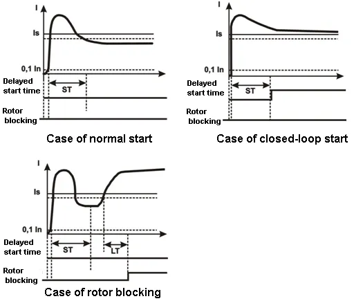
Figure 1.4 – Delayed start and rotor blocking
Delayed start:
During the motor start, protection is activated when the values of all phase currents exceed the Is threshold setting (the “PP5” parameter) during a time longer than the ST time delay value (the “PPt” parameter).
Rotor blocking:
After the motor start is complete (the starting current is less than 120% of the rated current), UBZ-302M switches to monitoring of possible rotor blocking. Protection is activated when the values of all phase currents exceed the threshold setting during a time longer than the LT time delay value (the “Pbt” parameter).
1.2.5.7 Thermal Overload Protection
Section titled “1.2.5.7 Thermal Overload Protection”Thermal overload protection is designed based on the electromotor thermal balance equation, with the following assumptions:
- the motor is cold before the first start;
- during operation, the motor releases heat, in the amount proportional to the current value squared;
- after the motor is stopped, it cools down exponentially.
To enable protection, set up the double overload tripping time Т2 (the “dtt” parameter).
Figure 1.5 shows the current-to-time curve for different T2 values.
The current-time dependence for the standard recommended T2 value (60 sec for double overload) is shown in Table 1.6.
Table 1.6
| I/Inom | 1.1 | 1.2 | 1.4 | 1.7 | 2 | 2.7 | 3 |
|---|---|---|---|---|---|---|---|
| Т, sec | 365 | 247 | 148 | 88.6 | 60 | 36.4 | 24.6 |
| I/Inom | 4 | 5 | 6 | 7 | 8 | 10 | 15 |
|---|---|---|---|---|---|---|---|
| Т, sec | 13.5 | 8.5 | 5.9 | 4.3 | 3.3 | 2.1 | 0.9 |
For rotary machines, cooling is more effective during operation than during the motor stall, which is why the dtP parameter is introduced – the cooling constant increase during motor stall.
After the load relay is open due to thermal overload, with automatic reclosing allowed, the relay will re-close after the bigger of the time values:
- duration of heat hysteresis (the motor should lose 33% of the accumulated heat);
- ARC time.
Through selection of suitable ARC times with regard to thermal hysteresis, the number of starts per time unit can be limited, because the device records the amount of heat released at the motor start when working in the intermittent cycle.
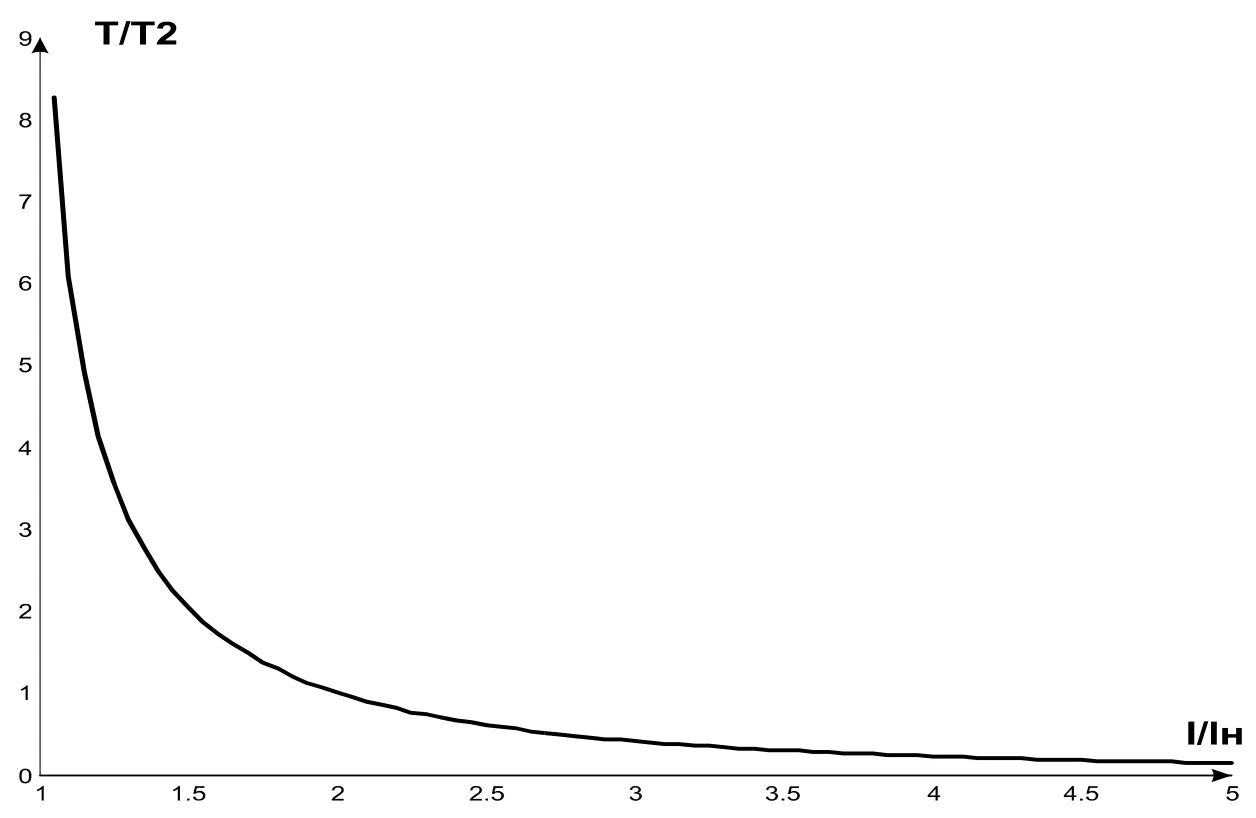
Figure 1.5 – Current-time curve
I/Iн – current value divided by rated current; Т/Т2 – actual tripping time divided by T2 (double load tripping time).
1.2.5.8 Coil Overheating Protection
Section titled “1.2.5.8 Coil Overheating Protection”Depending on the threshold settings selected, protection can use the first input with the following temperature sensors:
-
Integrated temperature sensors (
C1r=1). In this case, theC1Ssetting is not involved, and neither short circuit nor sensor breakout is monitored. Protection is activated when the sensor resistance exceeds 1700 Ohm. -
PTC type sensors (1 kOhm at 25 ºС) (this sensor should not be used to measure temperatures over 100 ºС).
At the second input, protection uses temperature sensors type Pt100 (platinum, 100 Ohm at 0 ºС) or Ni100 (Ni120) (nickel, 100 Ohm (120 Ohm) at 0 ºС) corresponding to IEC 60751 and DIN 43760 standards.
Protection at the second input:
- is activated when the monitored temperature exceeds the threshold setting;
- has two independent threshold setting: the alarm setting and the de-energize setting.
Protection detects the breakout and short circuit of temperature sensors:
- breakout at temperature over 220 °C;
- short circuit at temperature below minus 45 °C.
1.2.5.9 Voltage Protection
Section titled “1.2.5.9 Voltage Protection”In the scope of voltage protection, before the motor is energized, UBZ-302M checks whether the voltage parameters correspond to the user’s settings and, depending on the results, allows or forbids to energize the load. After the load is energized, UBZ-302M continues monitoring the voltage parameters, but any de-energizing decisions are made based on current values.
Voltage protection includes:
- undervoltage line protection (activated when at least one line voltage value remains below the threshold setting (the “
U₌5” parameter) during the time value in “U₌t”); - overvoltage line protection (activated when at least one line voltage value remains above the threshold setting (the “
U⁼5” parameter) during the time value in “U⁼t”); - line voltage imbalance protection (activated when the difference between the RMS line voltage values exceeds the threshold setting (the “
Uⁿ5” parameter) during the time value in “Uⁿt”).
1.2.5.10 Phase Sequence Protection
Section titled “1.2.5.10 Phase Sequence Protection”Phase Sequence Protection is activated when the phase sequence order is broken; the motor is de-energized, and its subsequent operation blocked.
1.2.5.11 Motor Coil Insulation Minimal Resistance
Section titled “1.2.5.11 Motor Coil Insulation Minimal Resistance”After the device receives voltage, but before the output relay closes, UBZ-302M checks the level of stator coil insulation relative to the body. This value is also checked when the load relay is closed, but the motor currents are less than 10% of the rated current (in this case, the motor is considered to be off).
At rid=5 (15), the load is not energized if the coil insulation is below 500 ± 20 kOhm; at rid=10 (20), if the coil insulation is below 1000 ± 50 kOhm. At rid=5 and rid=10, the load will be energized after the coil insulation is restored and the ARC time delay has passed. At rid=15 and rid=20, no ARC takes place.
1.2.5.12 Phase Loss Protection
Section titled “1.2.5.12 Phase Loss Protection”Phase Loss Protection is activated if the current at one of the motor’s phases exceeds 10% of the rated current (“ind”), while in any of the other phases, the current is under 7% of the rated current.
1.2.5.13 Control of external MS working order
Section titled “1.2.5.13 Control of external MS working order”UBZ-302M defines the engine currents presence at deactivated load relay (while load relay is deactivated and functional relay in mode star-delta). In this case the Unit initiates the alarm of external MS which starts the engine until the Unit is switched off or engine currents control is switched off while the load relay is deactivated (parameter CCi=0).
1.3 Packaging Contents
Section titled “1.3 Packaging Contents”The list of contents supplied is provided in Table 1.7.
Table 1.7 - Device Contents
| Description | Quantity |
|---|---|
| Unit UBZ-302М | 1 |
| Differential transformer (zero-sequence current transformer) | 1 |
| Cable for connection with PC via USB* (type: USB type A – microUSB) | 1 |
| Temperature sensor (types Pt100, Ni100 and Ni120)* | 1 |
| Operating manual | 1 |
| Packaging | 1 |
*Supplied on agreement with the consumer
1.4 Features and Operation
Section titled “1.4 Features and Operation”UBZ-302M is a microprocessor-based digital device that provides a high degree of reliability and accuracy. It requires no additional power supply, as the voltage it monitors is also used to power it.
UBZ-302M has three integrated CTs, through which the power phase cables are led.
2 Intended Usage
Section titled “2 Intended Usage”2.1 Safety
Section titled “2.1 Safety”Do not operate the unit under conditions of high humidity.
NEVER ATTEMPT TO OPERATE THE UNIT WITH THE MECHANICAL DAMAGE OF THE HOUSING.
DO NOT LET WATER INTO THE UNIT.
Do not use the unit in corrosive environments with the air containing acids, alkalis, oils, etc.
The unit is not intended for operation under vibrations or shocks.
If the temperature of the device after transportation or storage differs from the ambient temperature at which it is supposed to be operated, then before connecting to the mains keep the device under the operating conditions within two hours (because of condensation may be on the device elements).
This unit is safe for use in case of compliance with operating rules.
2.2 Device Controls
Section titled “2.2 Device Controls”2.2.1 UBZ-302M has five control modes:
Section titled “2.2.1 UBZ-302M has five control modes:”- keypad lock;
- mode with minimal number of setting parameters (MMSP);
- user level;
- engineer level;
- remote control.
All work modes allow:
- viewing the measures and displayed parameters (table 1.4). To scroll through parameters, use DOWN and UP buttons;
- viewing the fault log (p.2.4.6).
2.2.2 When the keypad is locked, viewing and editing programmable parameters is not possible.
Section titled “2.2.2 When the keypad is locked, viewing and editing programmable parameters is not possible.”When the keypad is locked, pressing the SETUP buttons will display the “LOC” message. To unlock the keypad, press SETUP again. The SETUP LED will be lit, and the indicator will show a flashing “0”. Use the UP and DOWN buttons, enter the user password (consisting of numbers 1 to 9) and press the RES/MEM/SEL button. If the password is correct, the keypad will be unlocked. If no button is pressed within 15 seconds of unblocking the keyboard, and the lock setting is not changed by the user, the keypad will be locked again.
2.2.3 When the keypad is unlocked, it is possible to:
Section titled “2.2.3 When the keypad is unlocked, it is possible to:”- work in MMSP mode;
- view and edit user-level parameters;
- view engineer-level parameters.
2.2.3.1 The MMSP mode is meant to simplify the use of UBZ-302M for service personnel.
To switch the UBZ-302M into the MMSP mode, set the value of 5in=1 or reset to factory settings (p.2.2.4). When UBZ-302M works in this mode, the green MMSP LED is on.
In the MMSP mode, the following parameters are sufficient for the normal operation of UBZ-302M:
- CT type (integrated or external);
- rated CT current (if using external CT);
- rated (operating) motor current.
The difference between MMSP mode and user mode is that the parameters not included in the MMSP list are set to default factory settings.
Parameters not included in the list in this mode are not viewed and not edited. Operations with the parameters included in the MMSP list is the same as in the user-level mode.
Adding parameters to the MMSP list and deactivating the MMSP list is only possible at the engineer level.
When the MMSP mode is deactivated (setting value of 5in=0), the MMSP LED switches off. In the user mode, the entire parameter list is viewed. To edit a parameter:
- use the DOWN and UP buttons to select the parameter to be added;
- press the DOWN and UP buttons simultaneously (the point in the higher digit of the mnemonic indicator should disappear).
2.2.3.2 Editing and Viewing User-Level Parameters
To view and edit user-level parameters, press SETUP – the SETUP LED will be illuminated. Scroll through the parameters using the DOWN and UP buttons; press SETUP to enter parameter editing mode (the parameter value will start flashing); edit the parameter value using the DOWN and UP buttons; press RES/MEM/SEL to save the parameter value, SETUP to return to the menu without saving, and RES/MEM/SEL to leave the menu. If no button is pressed during 30 seconds, UBZ-302M returns to the initial state.
2.2.3.3 Editing and Viewing Engineer-Level Parameters
Entering engineer mode
Press the SETUP button and keep pressed for 5 seconds. If engineer mode is password-protected, the indicator will display the “PAS” message. The SETUP LED will be illuminated, and the parameter value indicator will flash “000”. Use UP and DOWN to enter the engineer’s password (three digits from 1 to 9), pressing RES/MEM/SEL after each digit. If the password is wrong, the “PAS” message will be displayed, flashing in the higher digit; 15 seconds later, UBZ-302M will return to the initial state. If the password is correct, the first engineer menu parameter will be displayed.
To scroll through the parameters, use DOWN and UP; press SETUP to enter parameter editing mode (the parameter value will start flashing); edit the parameter value using the DOWN and UP buttons; press RES/MEM/SEL to save the parameter value, SETUP to return to the menu without saving, and RES/MEM/SEL to leave the menu. If no button is pressed during 30 seconds, UBZ-302M returns to the initial state.
When UBZ-302M is used in engineer mode, the decimal point is displayed in the lower digit of the mnemonic indicator.
At the engineer level, access to any user-level parameter can be granted or denied by pressing SETUP and DOWN simultaneously. Denied access is indicated by the decimal point displayed in the middle digit of the mnemonic indicator.
At the engineer level, any parameter can be added to the MMSP parameter list. To do that:
- use DOWN and UP to select the parameter to be added;
- press DOWN and UP simultaneously (the decimal point in the higher digit of the mnemonic indicator should disappear).
To remove a parameter from the MMSP parameter list:
- use DOWN and UP to select the parameter to be removed;
- press DOWN and UP simultaneously.
If the parameter is excluded from the MMSP list, the decimal point will be displayed in the higher digit of the mnemonic indicator.
2.2.4 Reset to Factory Settings
Section titled “2.2.4 Reset to Factory Settings”There are two ways of resetting UBZ-302M to default factory settings.
Method one. Set the value of PPP=1. After leaving the parameter setting mode, all factory settings will be reset (except for the engineer password).
Method two. When UBZ-302M is being powered on, press the buttons SETUP and RES/MEM/SEL and keep them pressed for two seconds. All factory settings will be reset, including the engineer password (engineer password set to 123).
After resetting to the default factory parameters, UBZ-302M will work in the MMSP mode, with the following list of parameters:
- CT type (external or integrated),
tPt; - rated CT current (for external CT),
tnt; - rated motor current,
ind.
2.2.5 UBZ-302M Alarms Reset on the front panel
Section titled “2.2.5 UBZ-302M Alarms Reset on the front panel”The Alarms Reset is to be carried out while the engine is switched off. For carrying out the Alarms Reset on the front panel it is necessary to press simultaneously the buttons RESET and DOWN, thereat:
- the alarms are being reset no matter whether the ARC is disabled or enabled (except for the current alarms on engine currents availability at the load relay being deactivated
CCi); - counting of ARC ends;
- if there are no new alarms, the engine starts.
2.3 Preparing UBZ-302M for Operation
Section titled “2.3 Preparing UBZ-302M for Operation”To ensure the reliability of electrical connections the flexible (stranded) wires with insulation for voltage of at least 450 V should be used, the ends of which it is necessary to be striped of insulation for 5±0.5 mm and tightened with bootlaces. It is recommended to use the wire with cross-section of at least 1 mm². Wires fastening should exclude mechanical damage, twisting and abrasion of the wire insulation.
IT IS NOT ALLOWED TO LEAVE EXPOSED PORTIONS OF WIRE PROTRUDING BEYOND THE TERMINAL BLOCK.
For a reliable contact, tighten the terminal screws with the force indicated in Table 1.1.
When reducing the tightening torque, the junction point is heated, the terminal block may be melted and wire can burn. If you increase the tightening torque, it is possible to have thread failure of the terminal block screws or the compression of the connected wire.
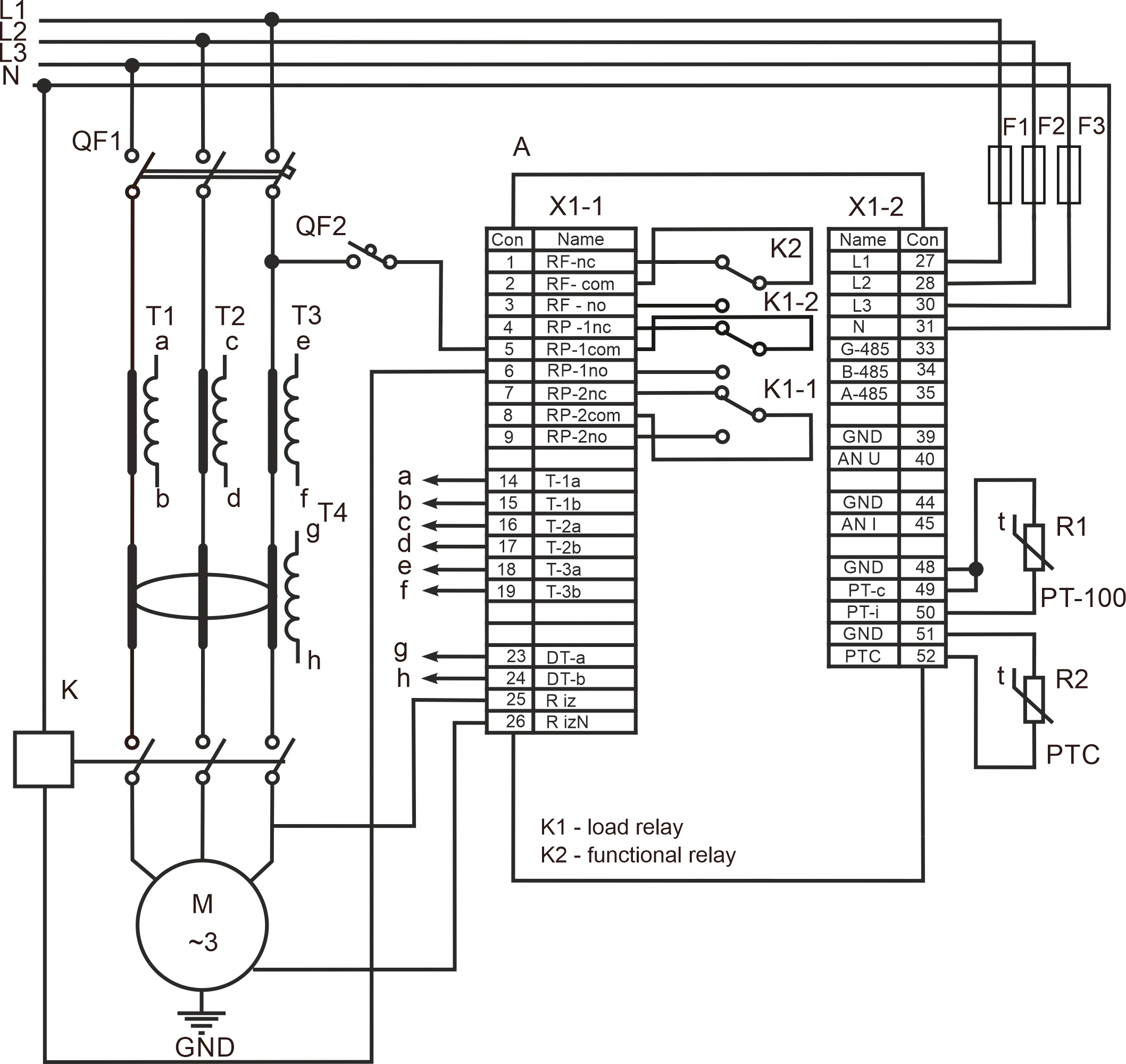
Figure 2.1 – UBZ-302M wiring chart
| Symbol | Description |
|---|---|
| А | UBZ-302M |
| QF1, QF2 | Circuit breaker |
| F1-F3 | fuses |
| R1, R2 | thermistor |
| K | electromagnetic starter |
| T1-T3 | current transformers |
| М | induction motor |
| T4 | differential transformer |
2.3.1 For electric motors of 2.5 kW to 30 kW capacity, integrated current transformers can be used. The wires to the motor should be led through the openings in the UBZ-302M housing (each phase wire through a separate opening).
For motors of other capacity, connect current transformers with 5 A rated output current, as shown in Figure 2.1.
2.3.2 Conduct all three phase wires through the differential current transformer (zero sequence transformer) and connect it to the UBZ-302M.
2.3.3 To monitor and measure the motor insulation, connect the insulation monitoring terminal 25 to one of the MS (magnetic starter) outputs. If the motor housing is not grounded, a circuit with isolated neutral is in use, or no neutral wire is connected to the UBZ-302M terminal – connect the motor housing to terminal 26 electrically.
If use a circuit with isolated neutral and the motor housing connect to compensating circuit of potentials that connect the motor housing to terminal 31 (“N”) UBZ-302M electrically.
2.3.4 Connect UBZ-302M to the electric circuit as shown in Figure 2.1. If using a motor with star-delta coil switching, connect as described in Appendix B.
2.3.5 If using the RS-485 interface, connect the communication lines to the UBZ-302M terminals 33 (GND), 34 (RS-485 B line), 35 (RS-485 A line). Set the value of “rPP=2”.
2.3.6 Power UBZ-302M on.
The procedure for the load relay closing is determined by the values of APd and dUd (p. 2.4.1.).
2.3.7 Set the necessary parameter values in the menu.
2.3.8 To operate UBZ-302M via a personal computer using the “UBZ-302M Control Panel” software install the “UBZ-302M Control Panel” software on the PC by running setup_cplubz302(Standart)(x.x).exe, where x.x. is the software version.
NOTE:
- The file setup_cplubz302(Standart)(x.x).exe can be downloaded from the website of NOVATEK-ELECTRO (http://novatek-electro.com/en/software.html).
- User-developed software can also be used to operate UBZ-302M.
2.3.9 For the device to work with a PC via the USB interface, you must:
- connect your PC to the Internet,
- upload a file to your PC “USB-serial-Novatek.rar” from the website of “NOVATEK-ELECTRO”,
- unpack the archive and install the driver on the PC by running the “setup.exe”,
- connect the “USB” connector on the device panel to the USB connector of PC using the “USB type A - microUSB” cable,
- select in the “COM port” “Communication settings” section (“Settings” menu of the “UBZ-302 Control Panel” program) the appeared number of additional COM-port and make sure that the other communication settings correspond to the UBZ-302M communication settings, and
- set the “
rPP=1” parameter in UBZ-302M.
2.3.10 Power UBZ-302M off.
2.3.11 Connect the magnetic starter (MS) as shown in Figure 2.1.
NOTE: when the load relay is on, contacts 5-6 and 8-9 are closed, when it is off, the contacts 4-5 and 7-8 are closed.
2.4 Intended Usage
Section titled “2.4 Intended Usage”2.4.1 UBZ-302M Operation Before Load Relay Activation
Section titled “2.4.1 UBZ-302M Operation Before Load Relay Activation”2.4.1.1 UBZ-302M Operation After Power On (First Use)
After the device is powered on, the mnemonic indicator displays “vEr” for 1-2 seconds. Then, before activating the load relay, UBZ-302M checks:
- the level of stator coil insulation relative to the body (if the insulation resistance is under 500 ± 20 kOhm at
rid=5 (1,000 ± 50 kOhm atrid=10), the load is not energized); - quality of voltage: phase completion, symmetry, RMS line voltage value;
- correct phase order, lack of phase coincidence.
In case any prohibiting factor is present, the load relay is not activated, the mnemonic indicator displays the appropriate fault code, and the FAULT LED is illuminated.
Depending on the value of 5iP, the indicator displays:
- linear voltage Uab at
5iP=0; - insulation resistance (
rid) at5iP=1; - ARC countdown in seconds (
Att) at5iP=2.
If no forbidding factors are present, activation of the load relay is determined by the value of APd (UBZ-302M operation after power-on).
- At
APd=0, the load relay will not be activated. At this setting, press UP and DOWN simultaneously to activate the load relay. - At
APd=1, the load relay will be activated after ARC delay time. - At
APd=2, the load relay will be activated 2 seconds after power-on.
At the same time as the load relay is activated, the green LOAD LED is illuminated. After the relay activation and before the motor start (the motor start is determined as the load current exceeding 120% of rated current), the voltage quality continues to be monitored, with appropriate decision-making. If any forbidding factors arose during the dead time, the load relay will be deactivated.
Describes UBZ-302M operation when remote motor control is allowed via the USB/RS-485 (dUd=1, dUd=2) interface.
2.4.1.2 UBZ-302M Operation After De-Energizing After Fault.
In this case, UBZ-302M operates as during first power-on, but activation of the load relay does not depend on the value of APd.
If ACR after fault is not allowed (Arr=0), the motor cannot be energized before UBZ-302M is powered off. The value of Arr applies to all types of faults, except voltage faults. To forbid ARC after voltage faults, use the parameters U⁼r, U₌r, Uⁿr.
2.4.2 UBZ-302M Operation After Load Relay Activation and Motor Energizing
Section titled “2.4.2 UBZ-302M Operation After Load Relay Activation and Motor Energizing”(currents of over 10% of the motor rated current)
UBZ-302M carries out voltage and current control. The load relay is deactivated when any protection type mentioned in Table 2.8 is tripped, except:
- voltage protection;
- overcurrent protection at
i⁼n=1 (in this case, overcurrent is indicated, but the load relay is not deactivated).
The indicator can display the motor phase A current or the value of the user-selected parameter. The value of the user-selected parameter can be displayed constantly (5iC=0) or during 15 seconds, after which the indicator resumes displaying the motor phase A current (5iC=1).
2.4.3 Functional Relay Operation
Section titled “2.4.3 Functional Relay Operation”The functions carried out by the functional relay are determined by the value of rr5.
At rr5=0, the relay is used as a signaling relay (the (Y/∆) and TR LEDs are not illuminated). The relay contacts are closed in case of any of the faults listed in Table 2.8.
At rr5=1, the relay is used as a time relay (the Y/∆ and TR LEDs are illuminated). The relay is activated after a time specified in “rrt”, after the load relay is activated.
At rr5=2, the relay is used to switch the motor coils from star to triangle (the Y/∆ LED is illuminated). In this mode, the load relay is activated the same as at rr5=0, but after the time specified in “rrt”, it is deactivated. Then, after a time specified in “Ftt” passes after the deactivation of the load relay, the functional relay is activated.
2.4.4 Using the USB/RS-485 Interface with the MODBUS Protocol, RTU Mode
Section titled “2.4.4 Using the USB/RS-485 Interface with the MODBUS Protocol, RTU Mode”UBZ-302M allows exchanging data with an external device using the serial interface. During data exchange via RS-485 or USB, the blue EXCHANGE LED is illuminated.
2.4.4.1 Communication Parameters:
- device address: 1-247 (parameter
rSA); - data transfer rate: 9,600 baud, 19,200 baud (parameter
rSS); - reaction to loss of link: warning with continued operation; warning with motor stopping; continued operation with no warning (parameter
rSP); - timeout detection: 1 –120 seconds (parameter
rSO); - word format – 8 bit, no parity check, two stop bits.
2.4.4.2 UBZ-302M Operation via PC
A PC is connected to the UBZ-302M via a serial interface. Each UBZ-302M has a unique communication address that is used by the PC to distinguish between different UBZ-302Ms. UBZ-302M can work in Modbus networks using the RTU mode.
2.4.4.3 Communication Protocol
The exchange between PC and UBZ-302M uses MODBUS protocol. The data formats, parameters addresses, command codes, and register maps are given in Appendix C: Modbus Communication.
2.4.5 Fault Status System
Section titled “2.4.5 Fault Status System”In case of a fault status:
- the mnemonic indicator displays a fault code as per Table 2.8;
- the value indicator displays the value of the parameter to which the fault is related (if the fault status has no numerical value, the indicator displays ”---”);
- the red FAULT LED is illuminated (steady glow if no ARC is allowed, or blinding if ARC is expected);
- the load relay opens;
- the functional relay closes (at
rr5=0).
If UBZ-302M detects several types of faults simultaneously, fault codes and their parameter values are displayed sequentially.
If ARC is allowed, the indicator displays fault codes and the time to ARC (if the time delay for thermal overload exceeds the ARC delay time, the former is displayed).
Table 2.8 - Fault Codes
| Fault name | Fault mnemonic | Parameter value | Param value register address | Fault code | N bit register address |
|---|---|---|---|---|---|
| phase overcurrent | Ai⁼ | maximum phase voltage | 300 | 0 | 241:0 |
| thermal overload | Adt | — | 301 | 1 | 241:1 |
| ground fault (zero sequence current) | Ai_ | zero sequence current | 302 | 2 | 241:2 |
| exceeded value of negative sequence current ratio divided by negative sequence voltage ratio | AiO | negative sequence current ratio × 100 | 303 | 3 | 241:3 |
| negative sequence current | Aio | negative sequence current | 304 | 4 | 241:4 |
| phase undercurrent | Ai₌ | — | 305 | 5 | 241:5 |
| delayed start | APP | current | 306 | 6 | 241:6 |
| rotor blocking | APb | current | 307 | 7 | 241:7 |
| temperature threshold at sensor 1 | At1 | temperature, degrees | 308 | 8 | 241:8 |
| temperature threshold at sensor 2 | At2 | temperature, degrees | 309 | 9 | 241:9 |
| phase sequence | AUЧ | — | 310 | 10 | 241:10 |
| External MS (by presence of currents with a load relay being disabled) | ACo | current | 311 | 11 | 241:11 |
| line undervoltage | AU₌ | voltage | 312 | 12 | 241:12 |
| line overvoltage | AU⁼ | voltage | 313 | 13 | 241:13 |
| phase imbalance | AUⁿ | imbalance | 314 | 14 | 241:14 |
| motor coil insulation resistance | Ari | insulation resistance | 315 | 15 | 241:15 |
| remote control channel fault | AdU | — | — | 16 | 242:0 |
| emergency motor stop without ARC | EAd | — | — | 17 | 242:1 |
| emergency motor stop with ARC, by simultaneous pressing of UP and DOWN | EOd | — | — | 18 | 242:2 |
| short circuit of temperature sensor 1 | ES1 | — | — | 19 | 242:3 |
| breakout of temperature sensor 1 | EO1 | — | — | 20 | 242:4 |
| short circuit of temperature sensor 2 | ES2 | — | — | 21 | 242:5 |
| breakout of temperature sensor 2 | EO2 | — | — | 22 | 242:6 |
| phase loss | EiU | — | — | 23 | 242:7 |
| EEPROM destruction | EEP | — | — | 24 | 242:8 |
| 0-20 mА analog input | AAi | — | 325 | 25 | 242:9 |
| 0-10 V analog input | AAU | — | 326 | 26 | 242:10 |
2.4.6 Fault Status Log
Section titled “2.4.6 Fault Status Log”When the load relay is deactivated in case of a fault, the UBZ-302M stores the fault code, the value of the parameter that caused the fault, and the time of the fault (the time passed between the UBZ-302M power on and the fault).
The maximum number of fault codes stored simultaneously is five. After subsequent faults, information about the fault overwrites the oldest entry.
To view the log, press RES/MEM/SEL.
The SETUP LED will be illuminated (flashing), and the UBZ-302M indicators will display the first row from Table 2.9. To scroll through the log, use UP and DOWN.
Table 2.9 - Fault log display
| Displayed on mnemonic indicator | Displayed on value indicator |
|---|---|
| ”Adi” | number of log entry (1 is the newest) |
| XXX – fault mnemonic according to Table 2.8 | YYY – parameter value as per Table 2.8 (if no parameter value, indicator displays ”---“) |
| XXX – hours since fault | YY – minutes since fault |
To leave the log, press RES/MEM/SEL. Otherwise, the log will be closed automatically, 30 seconds after any button was pressed.
Information about the fault is displayed on the UBZ-302M indicators in the format shown in Table 2.9.
When UBZ-302M is powered on, 5000000 is written into the registers used to store fault time. In this case, the mnemonic indicator and the value indicator display ”---” and ”–”, respectively.
2.4.7 Controlling the Motor Using the UBZ-302M Front Panel
Section titled “2.4.7 Controlling the Motor Using the UBZ-302M Front Panel”Depending on the value of ACd, the UBZ-302M load relay can be controlled using the buttons UP and DOWN (unless the keypad is locked):
ACd=0 – no reaction;ACd=1 (motor start allowed) – the load relay will close unless the ARC time has expired;ACd=2 (emergency motor stop) – the load relay will open, with fault code “EAd”. Motor restart is only possible after powering the UBZ-302M off and on again;ACd=3 (motor start and stop permitted) – the load relay opens, with fault code “EOd”. To energize, press the buttons UP and DOWN.
2.4.8 Controlling the Motor Using the Analog Inputs
Section titled “2.4.8 Controlling the Motor Using the Analog Inputs”Algorithms for controlling the motor using the analog inputs 0-20 mA and 0-10 V are provided in Table 1.5.
After motor de-energizing through a fault value, ARC countdown will only start after the parameter value leaves the fault range.
If, after motor de-energizing through a fault value, the value remains between the motor energizing and de-energizing levels (the FAULT indicator is not illuminated, but the mnemonic indicator displays the fault code), early motor start is possible, using the front panel buttons or remote control.
3 Technical Maintenance
Section titled “3 Technical Maintenance”3.1 Safety Precautions
Section titled “3.1 Safety Precautions”Do not use abrasives or organic compounds for cleaning (spirit, gasoline, solvents, etc.).
Installation, adjustment and maintenance of the unit should only be provided by the qualified personnel, having reviewed this Operating manual.
3.2 Technical Maintenance Procedure
Section titled “3.2 Technical Maintenance Procedure”Technical maintenance is recommended to make every 6 months.
Technical maintenance entails a visual examination, including checking that the wires are properly connected to the UBZ-302M terminals, and the housing is free of cracks and chips.
4 Transportation and Storage
Section titled “4 Transportation and Storage”UBZ-302M in the manufacturer’s package should be carefully stored in dry places with ambient temperature from -50 to +60 °C and relative air humidity not more than 80%. Air should not contain any chemically aggressive vapors. When transporting customer should provide suitable packing that would protect the UBZ-302M from any mechanical damages, serious drops and vibrations that may affect the device integrity.
5 Life Cycle and Manufacturer Warranty
Section titled “5 Life Cycle and Manufacturer Warranty”5.1 Device life cycle – 10 years. When expired, contact manufacturer.
5.2 Storage term – 3 years.
5.3 Warranty period of device maintenance is 5 years from sale day.
During maintenance warranty period (if device failure occurs) manufacturer repairs device for free.
5.4 Warranty service is performed on purchasing place or by manufacturer.
5.5 Post warranty service of device is performed by manufacturer on acting tariffs.
5.6 Before device is sent for repair, it shall be packed into original or other packing preventing mechanical damage.
With questions and comments, please contact manufacturer at the following address:
“Novatek-Electro” Ltd.
59, Mykhailo Boltenko (Admiral Lazarev) str., Odesa, Ukraine, 65007
Tel: +38 (067) 565 37 68; +38 (050) 359 39 11; +38 (063) 301 30 40
Appendices
Section titled “Appendices”- Appendix A: Time Delay Curves — Current protections with different time-dependent delay
- Appendix B: Star-Delta Mode — UBZ-302M operation by the motor in the star/delta switching mode
- Appendix C: Modbus Communication — Communication protocol and register map for MODBUS