Novatek-Electro TR-101 Documentation
https://www.overvis.com/docs/uk/tr-101/
2026-07-30
| |
|---|
Novatek-Electro TR-101
TR-101 — це цифрове температурне реле виробництва NOVATEK-ELECTRO LTD. Призначене для вимірювання та регулювання температури з використанням до чотирьох датчиків. Ключові особливостіSection titled “Ключові особливості”
ДокументаціяSection titled “Документація”
Технічна довідкаSection titled “Технічна довідка”Додаткові ресурсиSection titled “Додаткові ресурси”
ПідтримкаSection titled “Підтримка”
|
| | |||||||||||||||||||||||||||||||||||||||||||||||||||||||||||||||||||||||||||||||||||||||||||||||||||||||||||||||||||||||||||||||||||||||||||||||||||||||||||||||||||||||||||||||||||||||||||||||||||||||||||||||||||||||||||||||||||||||||||||||||||||||||||||||||||||||||||||||||||||||||||||||||||||||||||||||||||||||||||||||||||||||||||||||||||||||||||||||||||||||||||||||||||||||||||||||||||||||||||||||||||||||||||||||||||||||||||||||||||||||||||||||||||||||||||||||||||||||||||||||||||||||||||||||||||||||||||||||||||||||||||||||||||||||||||||||||||||||||||||||||||||||||||||||||||||||||||||||||||||||||||||||||||||||||||||||||||||
|---|---|---|---|---|---|---|---|---|---|---|---|---|---|---|---|---|---|---|---|---|---|---|---|---|---|---|---|---|---|---|---|---|---|---|---|---|---|---|---|---|---|---|---|---|---|---|---|---|---|---|---|---|---|---|---|---|---|---|---|---|---|---|---|---|---|---|---|---|---|---|---|---|---|---|---|---|---|---|---|---|---|---|---|---|---|---|---|---|---|---|---|---|---|---|---|---|---|---|---|---|---|---|---|---|---|---|---|---|---|---|---|---|---|---|---|---|---|---|---|---|---|---|---|---|---|---|---|---|---|---|---|---|---|---|---|---|---|---|---|---|---|---|---|---|---|---|---|---|---|---|---|---|---|---|---|---|---|---|---|---|---|---|---|---|---|---|---|---|---|---|---|---|---|---|---|---|---|---|---|---|---|---|---|---|---|---|---|---|---|---|---|---|---|---|---|---|---|---|---|---|---|---|---|---|---|---|---|---|---|---|---|---|---|---|---|---|---|---|---|---|---|---|---|---|---|---|---|---|---|---|---|---|---|---|---|---|---|---|---|---|---|---|---|---|---|---|---|---|---|---|---|---|---|---|---|---|---|---|---|---|---|---|---|---|---|---|---|---|---|---|---|---|---|---|---|---|---|---|---|---|---|---|---|---|---|---|---|---|---|---|---|---|---|---|---|---|---|---|---|---|---|---|---|---|---|---|---|---|---|---|---|---|---|---|---|---|---|---|---|---|---|---|---|---|---|---|---|---|---|---|---|---|---|---|---|---|---|---|---|---|---|---|---|---|---|---|---|---|---|---|---|---|---|---|---|---|---|---|---|---|---|---|---|---|---|---|---|---|---|---|---|---|---|---|---|---|---|---|---|---|---|---|---|---|---|---|---|---|---|---|---|---|---|---|---|---|---|---|---|---|---|---|---|---|---|---|---|---|---|---|---|---|---|---|---|---|---|---|---|---|---|---|---|---|---|---|---|---|---|---|---|---|---|---|---|---|---|---|---|---|---|---|---|---|---|---|---|---|---|---|---|---|---|---|---|---|---|---|---|---|---|---|---|---|---|---|---|---|---|---|---|---|---|---|---|---|---|---|---|---|---|---|---|---|---|---|---|---|---|---|---|---|---|---|---|---|---|---|---|---|---|---|---|---|---|---|---|---|---|---|---|---|---|---|---|---|---|---|---|---|---|---|---|---|---|---|---|---|---|---|---|---|---|---|---|---|---|---|---|---|---|---|---|---|---|---|---|---|---|---|---|---|---|---|---|---|---|---|---|---|---|---|---|---|---|---|---|---|---|---|---|---|---|---|---|---|---|---|---|---|---|---|---|---|---|---|---|---|---|---|---|---|---|---|---|---|---|---|---|---|---|---|---|---|---|---|---|---|---|---|---|---|---|---|---|---|---|---|---|---|---|---|---|---|---|---|---|---|---|
TR-101 Operating Manual
NOVATEK-ELECTRO LTD Intelligent Industrial Electronics DIGITAL TEMPERATURE RELAY TR-101 OPERATING MANUAL Quality control system on the development and production complies with requirements ISO 9001:2015 Dear customer, Company NOVATEK-ELECTRO LTD. thanks you for purchasing our devices. You will be able to use properly the device after carefully studying the Operating Manual. Keep the Operating Manual throughout the service life of the device. UKRAINE, Odesa — www.novatek-electro.com This unit is safe for use in case of compliance with operating rules. This manual is provided in order to introduce the operating personnel with structure, operating principle, design, mode of operation and maintenance of TR-101 digital temperature relay (further referred to as “device”, “TR-101” or “TR-101 unit”). TR-101 complies with requirements:
No harmful substances in excess of the maximum permissible concentration is available. 1 ApplicationSection titled “1 Application”TR-101 is designed for measuring and controlling a device temperature by means of four sensors connected according to a two- or three-wire diagram, with subsequent temperature display. The device can find various applications in industrial sector, in municipal utilities service, and agriculture. The device allows for performing the following functions:
TR-101 has a flexible power supply and can use any voltage from 24 to 260 V, regardless of polarity. Supported Temperature SensorsSection titled “Supported Temperature Sensors”TR-101 can use the following types of temperature sensors: Table 1 – Supported Temperature Sensors
2 Technical Specifications and Operating ConditionsSection titled “2 Technical Specifications and Operating Conditions”2.1 Basic Technical ParametersSection titled “2.1 Basic Technical Parameters”Table 2 – Basic Technical Parameters
Output Contacts SpecificationSection titled “Output Contacts Specification”
2.2 Operating ConditionsSection titled “2.2 Operating Conditions”The device is designed for operating in the following environment:
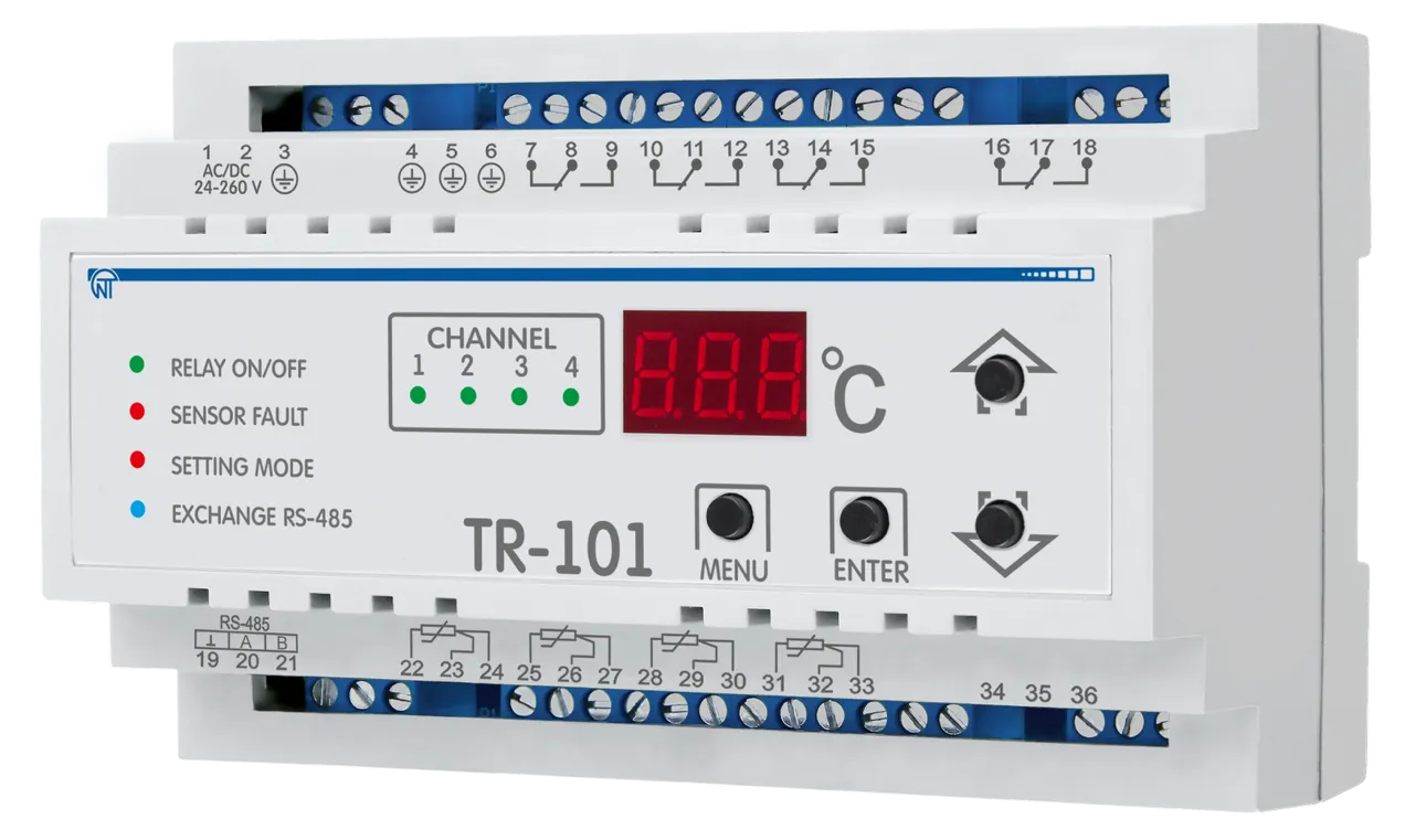
3 Equipment Design and OperationSection titled “3 Equipment Design and Operation”3.1 TR-101 Device EquipmentSection titled “3.1 TR-101 Device Equipment”Display SymbolsSection titled “Display Symbols”Trace of symbols at numeric display to letters of Roman alphabet is shown in Figure 3.
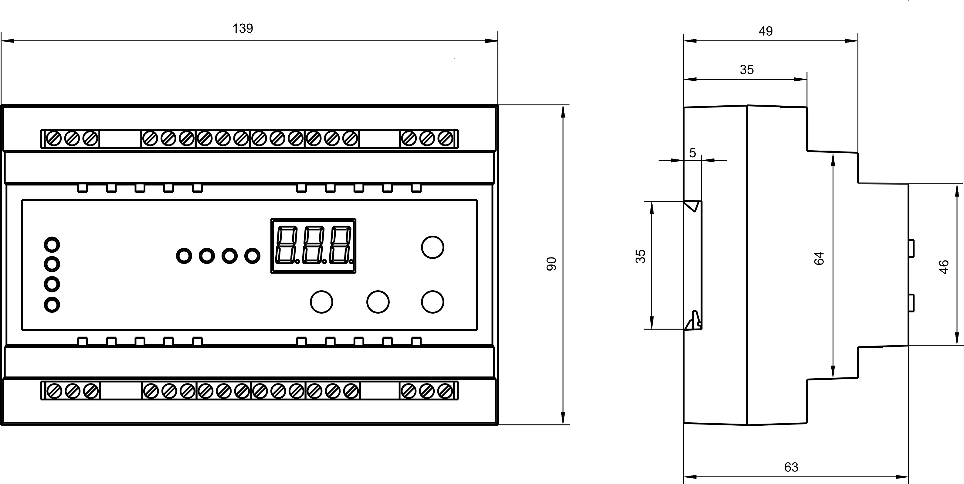
Figure 3 – Trace of symbols at numeric display to letters of Roman alphabet 3.1.1 DesignSection titled “3.1.1 Design”The device is manufactured in plastic casing (9 S-type modules) to be mounted onto standard DIN rail. The casing outline with overall and mounting dimensions is presented in Figure 3.1.
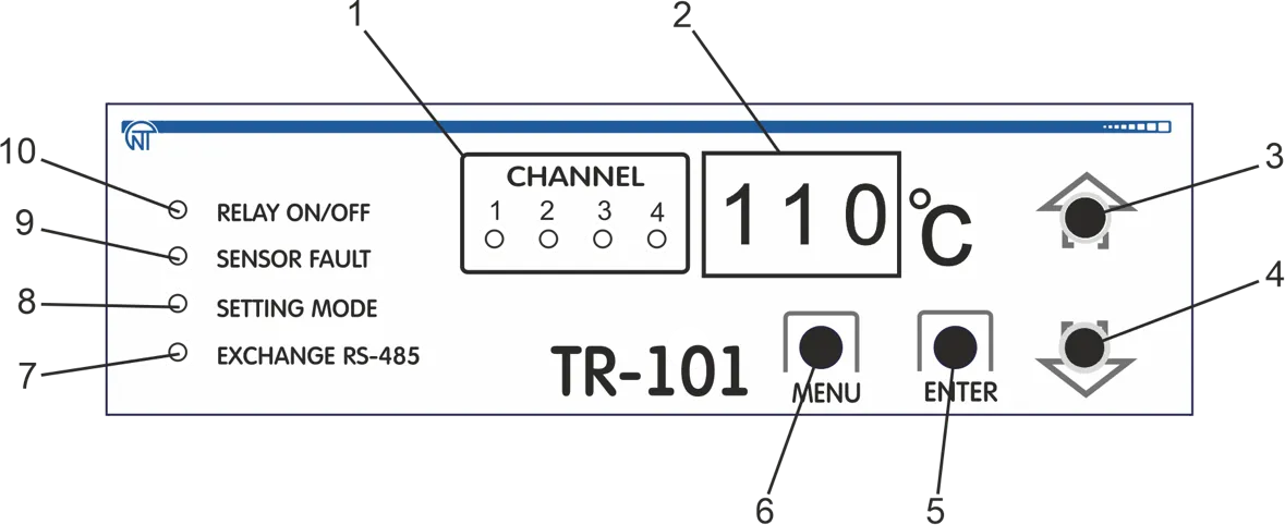
Figure 3.1 – TR-101 dimensions 3.1.2 Display and ControlSection titled “3.1.2 Display and Control”Figure 3.2 presents the TR-101 front panel Exterior.
Front Panel Elements:
Figure 3.2 – TR-101 Front Panel In the menu mode, indicators (1, 7) display the corresponding parameter (on/off): Device control:
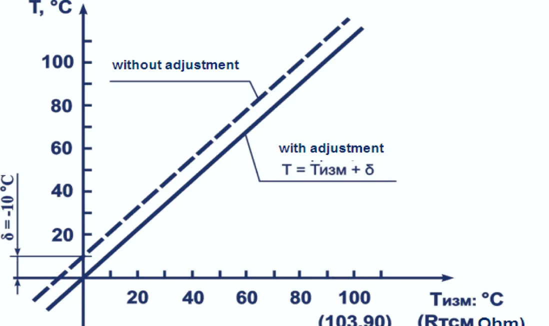
3.2 Operating Principle and Input Signal ProcessingSection titled “3.2 Operating Principle and Input Signal Processing”3.2.1 Operating PrincipleSection titled “3.2.1 Operating Principle”In course of its operation, TR-101 performs input sensors scanning, then, based on the data obtained, calculates the current temperature value and outputs it on the digital display and sends control signals to the corresponding channel relay. 3.2.2 Input Signal ProcessingSection titled “3.2.2 Input Signal Processing”The signal that is received from sensor is transformed into a temperature digital value. In order to eliminate the initial input signal processing error, as well as errors that are produced by the connection wiring, the device measured value can be adjusted. TR-101 provides for two adjustment types, which allow performing a gain shift or sloping by a specified degree for each channel independently. 3.2.3 Measurements AdjustmentSection titled “3.2.3 Measurements Adjustment”3.2.3.1 Characteristic Shift To provide for the error compensation ΔR = (R0 - R0.TC) produced by the input wiring resistance RTC, each measured temperature value (Tmeas) is added with a user specified value δ. Figure 3.3 shows an example of a characteristics shift for Pt100 sensor. Programmable parameters:
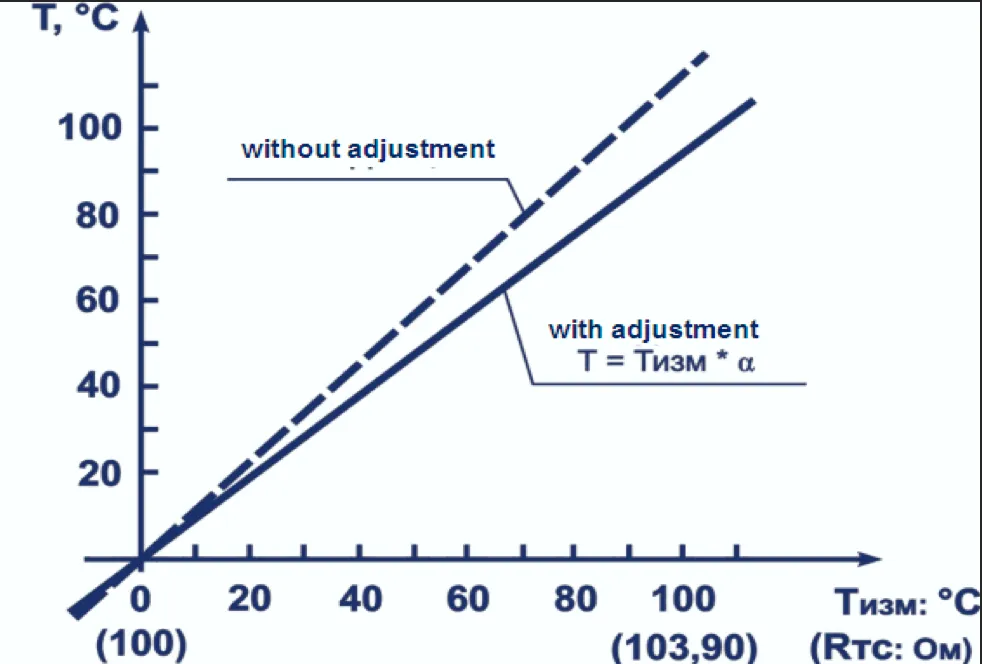
Figure 3.3 – Characteristic shift example for Pt100 sensor 3.2.3.2 Characteristic Slope To provide for sensor error compensation upon W100 value deviation from the rated value, each Tmeas parameter measured value is multiplied by the user set adjustment parameter α. The ratio boundaries are set within 0.50 to 2.00 limits. Figure 3.4 shows an example of the characteristic slant variation for Pt100 sensor. Programmable parameters:
Figure 3.4 – Characteristic slope example for Pt100 sensor 3.2.4 Digital FilterSection titled “3.2.4 Digital Filter”To provide for the input signal properties improvement the device employs digital filters that allow reducing the random interference effect on the temperature measurement. Programmable parameters:
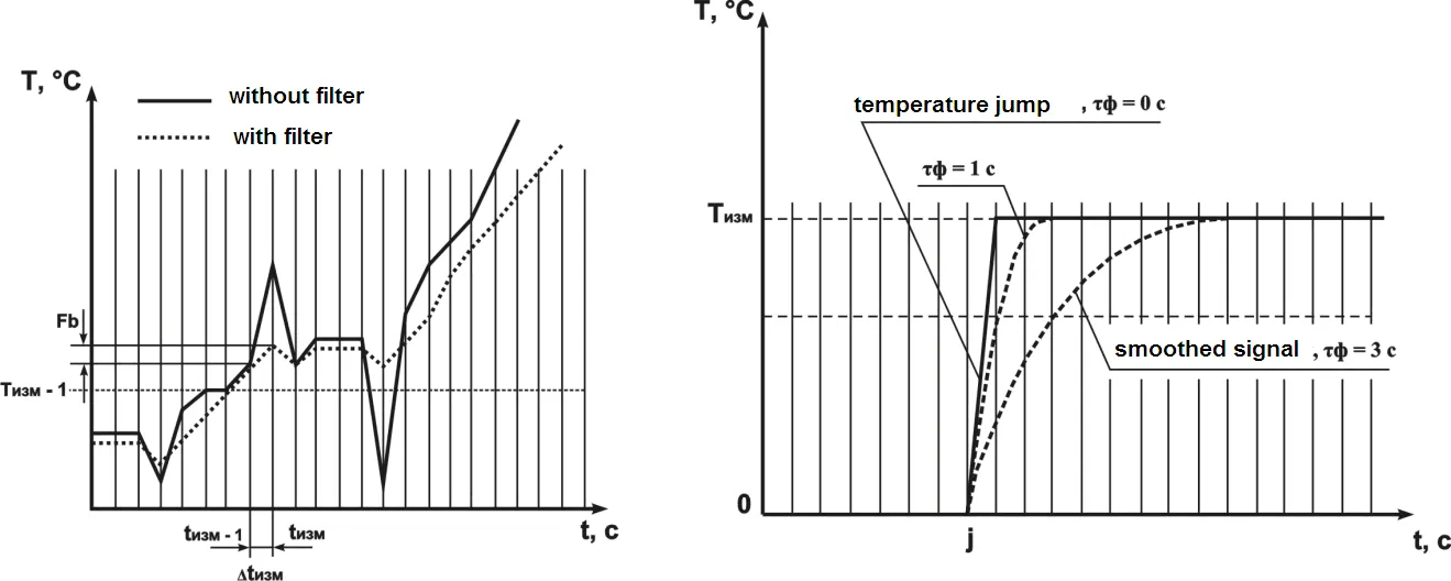
The filters are set for each input independently. 3.2.4.1 Digital Filter Band The digital filter band allows protecting the measurement route from single interference and is set in °C. If the measured value Tmeas is different from the previous Tmeas–1 by the value larger than the Smaller band width of the filter leads to slowing down the device reaction to temperature change. That is why in case of low interference level or during operation with discontinuous temperatures it is recommended to increase the parameter value or switch off the filter band action by setting the When working under strong interference, in order to eliminate its impact onto the device operation, it is necessary to reduce the parameter value. 3.2.4.2 Digital Filter Time Constant The digital filter eliminates the noise signal components by smoothing it exponentially. The main characteristic of the exponential filter is τf – the digital filter time constant, Reducing τf will lead to a faster device reaction onto discontinuous temperature variations, but also will reduce its protection against interference. Increasing τf value increases the device response rate, while noise is significantly suppressed.
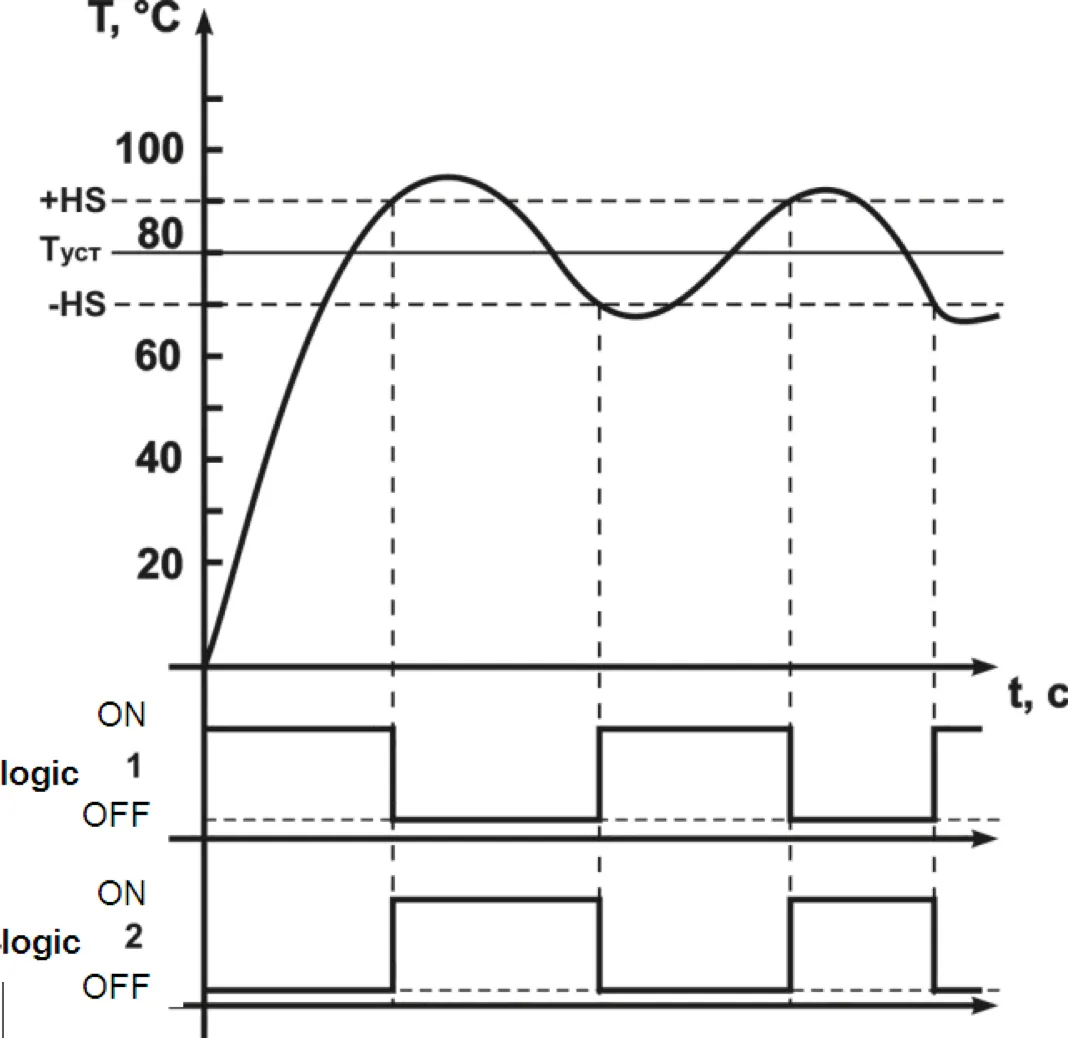
Figure 3.5 – Filter band characteristic Figure 3.6 – Filter time constant characteristic 3.2.5 Two-Position Regulator (Two-Position Control)Section titled “3.2.5 Two-Position Regulator (Two-Position Control)”In the two-position control mode the device works according to one of the two logic types: Logic №1 (Heater) – used to control a heater operation (tubular electric heaters, for instance), or to produce warning that the current temperature value (Tcurr) is less than the setting value (Tset).
This effects the two-position control by Tset setting with the HS hysteresis. Logic №2 (Cooler) – used to control a cooler operation (a fan, for instance), or a warning of exceeding Tset setting value.
Figure 3.7 – Diagram of output relay function based on the logic type Programmable parameters:
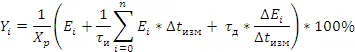
3.2.6 PID-Controller (Proportional-Plus-Integral-Plus-Derivative Control)Section titled “3.2.6 PID-Controller (Proportional-Plus-Integral-Plus-Derivative Control)”3.2.6.1 PID Control General PrinciplesSection titled “3.2.6.1 PID Control General Principles”On the control relay the “controlling” signal Yi is generated; its action is directed at reducing the Ei deviation.
Where:
To provide for the efficient PID controller operation it is important that proper values of Xp, τd and τi ratios for the given controlled object be set. Programmable parameters:
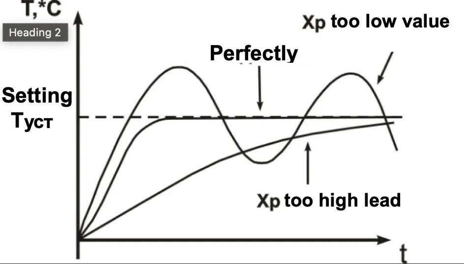
3.2.6.2 Proportional RegulatorSection titled “3.2.6.2 Proportional Regulator”Proportional regulator is the main where the task of temperature is directly proportional to error. Using only proportional regulator leads to error. The low values of proportional regulator lead to lack of stability and vibration in system but too high lead to low operation.
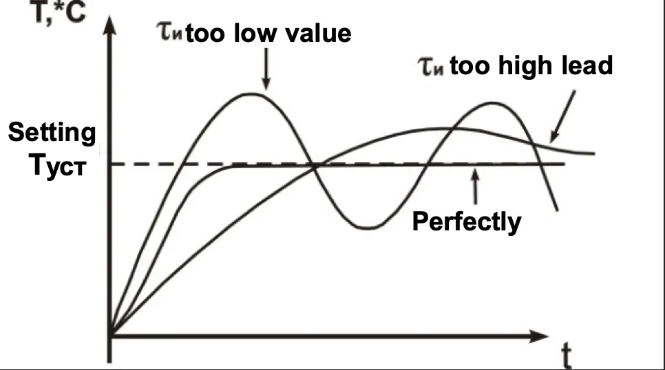
Figure 3.8 – Working diagram of proportional regulator 3.2.6.3 Integral RegulatorSection titled “3.2.6.3 Integral Regulator”It’s used for compensation of errors. The temperature will grow to the moment compensation of errors (or diminish by negative error). The minor constituents of integral element influence the regulator job much. If the value fixed very high it means the system doesn’t recognize it and will work with overshoot.
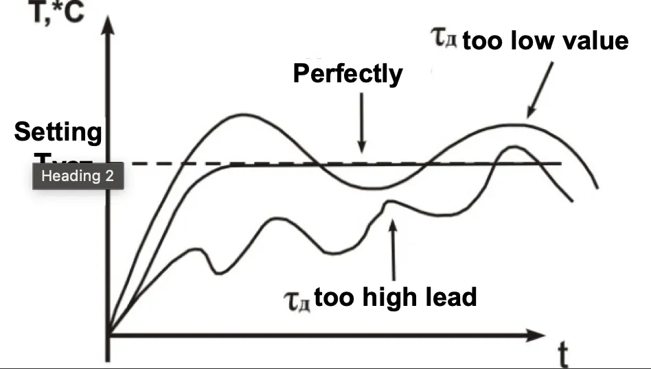
Figure 3.9 – Working diagram of integral regulator 3.2.6.4 Differential RegulatorSection titled “3.2.6.4 Differential Regulator”It’s used for increasing system performance rating the error change. The regulator speeding leads to increasing overshoot and as a result is lack of stability the system. Most cases derivative term is fixed neutral or low value to avoid this lack of stability.
Figure 3.10 – Working diagram of differential regulator 3.2.6.5 Methods of PID ControllingSection titled “3.2.6.5 Methods of PID Controlling”During the controlling, one of the control methods is selected: “Heater” or “Cooler”.
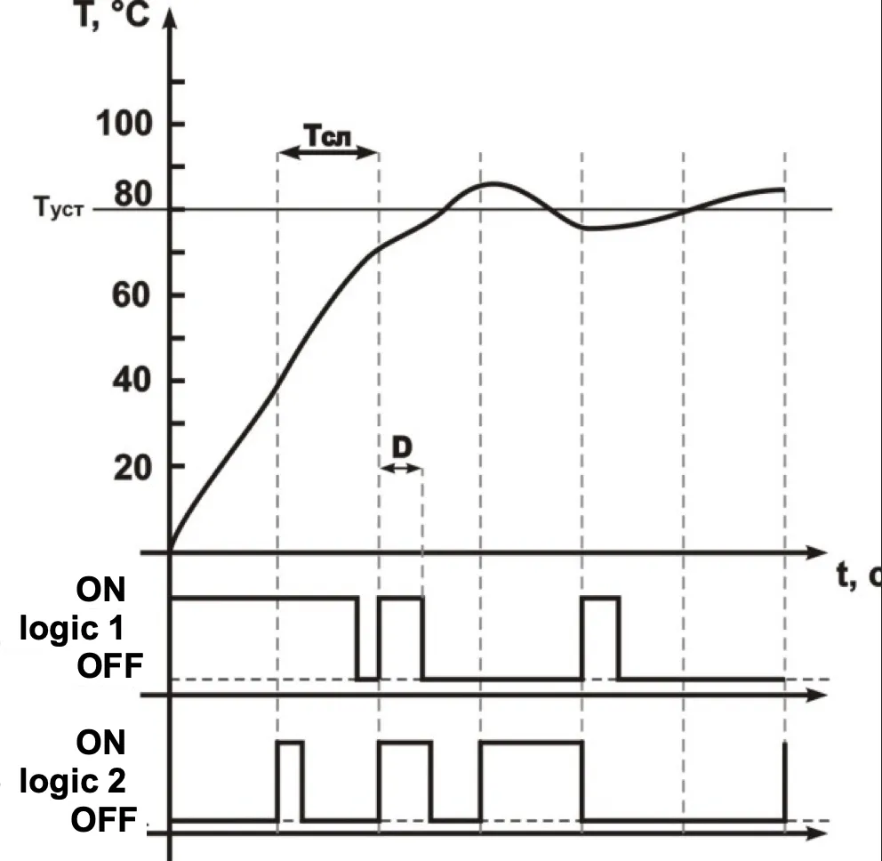
Programmable parameters: 3.2.6.6 Action in PID-Regulator Mode with Output Key Element (Pulse-Length Modulation)Section titled “3.2.6.6 Action in PID-Regulator Mode with Output Key Element (Pulse-Length Modulation)”Command current from PID regulator (Yi) is transforming to multiple pulses according to the following formula: D = Tcycle × Yi / 100 Where:
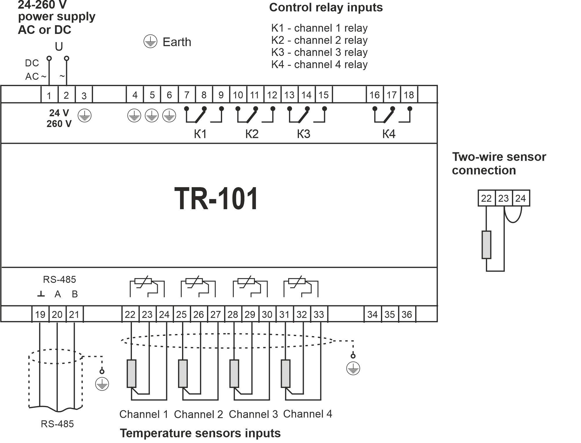
Figure 3.11 – Diagram of output relay action in PID regulation mode 3.2.7 RS-485 Communication InterfaceSection titled “3.2.7 RS-485 Communication Interface”Using of interface is described in Appendix A. 4 Maintenance and SafetySection titled “4 Maintenance and Safety”4.1 SafetySection titled “4.1 Safety”Open terminals of the device carry dangerous voltage of up to 250 V. Any connections to the device and its maintenance operations must be performed only on de-energized device and executive units. Ingress of moisture to the output terminals and the device inside electronic elements is not allowed. The use of the device in aggressive environments containing acids, alkali, oils, etc. is prohibited. The device connection, adjustment and maintenance must be performed only by authorized personnel that is familiar with this manual. 4.2 Maintenance ScheduleSection titled “4.2 Maintenance Schedule”Recommended maintenance schedule – semiannually. Maintenance scheduled operations consist of visual observation, during which wiring connection to terminals is checked, frame and casing integrity check for cracking and chipping. During maintenance operations, the safety precautions listed in chapter 4.1 must be followed. 5 Device ConnectionSection titled “5 Device Connection”5.1 Periphery ConnectionsSection titled “5.1 Periphery Connections”5.1.1 General InstructionsSection titled “5.1.1 General Instructions”Prepare cables for connecting the device to sensors, execution mechanisms and peripheral equipment, as well as to the power supply. To provide for the electric connections reliability it is recommended to use cables with copper stranded wires, the ends of which should be carefully cleaned and soldered prior to connecting. The wire core shall be cleared in such way, that its bare ends would not project beyond the terminals after connection to the device. The cable section must not exceed 2.5 mm². 5.1.2 Mounting Instructions Aimed at Electromagnetic Interference ReductionSection titled “5.1.2 Mounting Instructions Aimed at Electromagnetic Interference Reduction”When laying the “device-sensor” lines, they should be separated into an individual tract (or several tracts). The tracts shall be placed separately from the power cables, as well as from cables that produce high frequency and pulse interference. 5.1.3 Mounting Instructions Aimed at Reduction of the Power Circuit InterferenceSection titled “5.1.3 Mounting Instructions Aimed at Reduction of the Power Circuit Interference”The device shall be connected to 220V 50Hz circuit feeder that is not connected with supplying power to heavy-duty industrial equipment. It is recommended to install in the peripheral supply line a feed switch providing disconnecting the device from the circuit, as well as 1A fuses. 5.2 Device ConnectionSection titled “5.2 Device Connection”The device shall be connected in accordance with the diagram on Figure 5.1, observing the listed below sequence: A) Connect the device to power supply and execution units; B) Connect the “device-sensor” communication lines to the device inputs. 5.3 Connecting Sensors (RTDs)Section titled “5.3 Connecting Sensors (RTDs)”TR-101 devices employ a three-wire diagram for connecting RTDs (resistance temperature detectors). Two wires are connected to one of the RTD outputs, and the third wire is connected to the other RTD output (see Figure 5.1). Such diagram, provided that impedance of all three wires is equal, allows to compensate its impact onto the temperature measurement. The resistance temperature detectors can be connected to the device under a two-wire diagram as well, but such arrangement does not provide for the connecting wiring impedance compensation which may lead to certain dependence of the device measurement from the wires temperature variation. 5.3.1 Connecting Sensors (RTDs) According to a Two-Wire DiagramSection titled “5.3.1 Connecting Sensors (RTDs) According to a Two-Wire Diagram”5.3.1.1 The RTDs (resistance temperature detectors) are connected to the device according to a two-wire diagram in case when a three-wire diagram cannot be used, for example, when TR-101 is installed within units equipped with earlier laid two-wire connection lines. 5.3.1.2 Please, mind that the device readings will depend on the “device-sensor” communication line wires impedance change, that takes place under influence of the outside air temperature. To compensate for the wires parasitic resistance, perform the following:
Figure 5.1 – TR-101 Connection Diagram 6 TR-101 OperationSection titled “6 TR-101 Operation”6.1 General InformationSection titled “6.1 General Information”6.1.1 When the device is powered on, all displays light up for 2 seconds. After that on the digital display the measured temperature for Channel 1 is shown. The device sequentially displays the temperature of the active channels with 4 sec interval. 6.1.2 In case of certain faults presence, the device displays the error code (Table 6.1). Table 6.1 – Error Codes
6.2 Output Relay TestingSection titled “6.2 Output Relay Testing”The device gives an opportunity to test both all relays at once, or each relay independently; to test, perform the following:
7 ProgrammingSection titled “7 Programming”7.1 General InformationSection titled “7.1 General Information”7.1.1 Programmable parameters are set by the user during programming session and are stored in device’s nonvolatile memory. The complete list of programmable parameter registers is given in Table 7.1. Table 7.1 – Programmable Parameters General ParametersSection titled “General Parameters”
System ParametersSection titled “System Parameters”
RS-485 ParametersSection titled “RS-485 Parameters”
Channel 1 ParametersSection titled “Channel 1 Parameters”
Channel 2 ParametersSection titled “Channel 2 Parameters”
Channel 3 ParametersSection titled “Channel 3 Parameters”
Channel 4 ParametersSection titled “Channel 4 Parameters”
Notes:
Sensor Type CodesSection titled “Sensor Type Codes”
7.1.2 Viewing ParametersSection titled “7.1.2 Viewing Parameters”To view parameters, press MENU key once, the display will show parameter 1 from Table 7.1. Scroll parameters with ▲▼, parameter view – press key ENTER, passage back to menu – press key MENU. 7.1.3 Editing ParametersSection titled “7.1.3 Editing Parameters”To edit parameters, press and hold MENU key for 7 seconds, at that:
Use ▲▼ keys to toggle parameters, use ENTER key to store parameter and return to menu, to return to menu without storing parameter, press MENU key. If no key is pressed during 20 sec the device goes into the initial state. 7.1.4 Reset to Factory SettingsSection titled “7.1.4 Reset to Factory Settings”Method 1:
In the parameter edit mode (p. 7.1.3) set Method 2:
Energize the device while pressing down ▲▼ keys and hold them pressed for over 2 seconds, at that the display will show 7.2 Programming SequenceSection titled “7.2 Programming Sequence”7.2.1 Setting Up Measurement Entry ParametersSection titled “7.2.1 Setting Up Measurement Entry Parameters”7.2.1.1 Enter the 7.2.1.2 Measurement Characteristic Adjustment The measurement adjustment procedure performed by the device is described in paragraph 3.2.3. The device performs measurement adjustment after the necessary values for parameters
7.2.2 Setting Up Digital Filter ParametersSection titled “7.2.2 Setting Up Digital Filter Parameters”The digital filter operation is described in paragraph 3.2.4. The measurement digital filter setting up is performed by specifying two parameters values:
The The 7.2.3 Setting Up Relay Control Method ParametersSection titled “7.2.3 Setting Up Relay Control Method Parameters”For a specific regulation system, the control method has to be selected by means of setting corresponding values to
7.2.4 Setting Control ModesSection titled “7.2.4 Setting Control Modes”The device can function in one of the two modes: the two-position control and PID-control. The proper mode is set by specifying a proper value for
The two-position control and PID control operation is described in paragraphs 3.2.5 and 3.2.6. The two-position controller hysteresis 7.2.5 PID Regulator AdjustmentSection titled “7.2.5 PID Regulator Adjustment”7.2.5.1 General Concept PID regulator operation is described at p. 3.2.6. For adjustment of PID regulator needed attend following actions:
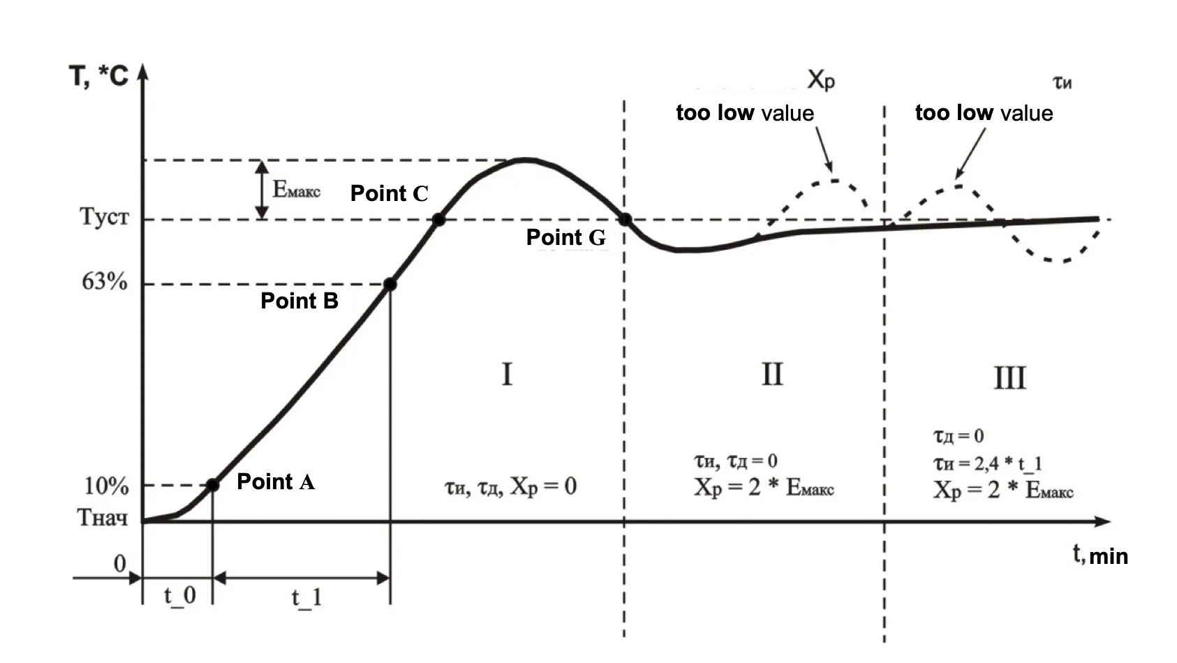
Option setting Option setting Option setting Option setting Option setting For Considering that at each individual scheme there are non-periodic External actions of different characters, all coefficients in above shown formulas can change for getting optimal behavior in positive conditions. Selected parameters for superfine temperature maintenance in steady-state may happen totally unacceptable for suppression transient phenomena for External action or on-exit onto mode. As well as alternatively. For another thing in the course of operation controlled plant characteristic regulation can change very much. Like for operational changes and in time. Usually calculated values require repeated correcting and selection. And changing single parameter involves necessity correcting other. 7.2.5.2 Automatic Adjustment of PID Regulator This mode designed to autodetection initial approximate values of PID coefficients τi, τd and Xp when operated at concrete scheme. Automatic tuning is recommended to lead by start and system debugging. 7.2.5.2.1 Enter to program mode (see p. 7.1.3). 7.2.5.2.2 Define If necessary fix PLM pulses repetition period and minimal PLM pulse length, parameters Factory settings are 7.2.5.2.3 Define parameter After pressing key ENTER, at display device will appear blinking caption On the morrow of time regulator will give continuous output limit and at display device will appear current temperature dotted in low order position “xxx.”. Whereby output relay of loading will be power on till will not be reach the volume of temperature like After switching off loading relay (period I, point B) sometime the temperature mechanically will increase further. As soon as the control temperature will come down below TR-101 calculates coefficient of PID regulator: band proportionality, characteristic time of integration, characteristic time of differentiator. After finishing automatic tuning needed press key MENU and switch device to program mode in which is possible to look and correct received coefficients value. The coefficients were received as a result of “Automatic tuning PID” are not optimal and work for preliminary analysis. 7.2.5.3 PID Regulator Manual Setting Below mentioned method allows defining approximate generic parameters of regulator. 7.2.5.3.1 Enter to program mode. 7.2.5.3.2 If necessary, fix PLM pulses repetition period and minimal PLM pulse length, parameters Factory settings are 7.2.5.3.3 Fix the value equal to zero for After passage to mode regulation (at the end of 20 seconds the device automatically passes into mode regulation) output relay of loading will be power on till fail to reach regulation temperature (setting limit) Tset (period I, point B at Figure 7.1). 7.2.5.3.4 Take measure t₁ – time from the moment of temperature increase to 10% (point A at Figure 7.1) and to the moment of temperature increase to 63% from the range Tset − Tmax (point B at Figure 7.1). 7.2.5.3.6 Take measure of maximum value overshoot between points B and G (Emax, Figure 7.1). 7.2.5.3.7 Fix the value Xp = 2 × Emax (period II at Figure 7.1). Make sure that for datum value Xp does not absent achievement of setting value Tset. Otherwise necessary increase the value Xp. If the value of Xp = 2 × Emax and the difference between steady-state temperature and setting value is too much, then need to diminish Xp. 7.2.5.3.8 Fix the value τi = 2.4 × t₁. Make sure that given value τi not appear temperature vibration around setting value (period III). For decreasing vibration is necessary increase value τi, for increasing delivery speed necessary diminish value τi. 7.2.5.3.9 Fix the value τd equal to [0.1; 0.2; 0.3; 0.4] × τobj.
Figure 7.1 – PID regulator manual tuning diagram 8 Service Life, Shelf Life and Manufacturer WarrantySection titled “8 Service Life, Shelf Life and Manufacturer Warranty”8.1 The unit service life is 10 years. Upon expiration of the service life you should contact the Manufacturer. 8.2 Shelf life is 3 years. 8.3 Warranty period of the unit operation is 5 years from the date of sale. During the warranty period the Manufacturer is responsible for free repair of the unit, if the Consumer has complied with the requirements of this Operating Manual. 8.4 Warranty service is performed at the place of purchase or by the Manufacturer of the product. 8.5 Post-warranty service is performed by the Manufacturer at current rates. 8.6 Before sending for repair, the unit should be packed in the original or other packaging excluding mechanical damage. 9 Storage and Shipping ConditionsSection titled “9 Storage and Shipping Conditions”The device in manufacturer package should be stored in enclosed rooms at -45 to +60 °C and exposed to no more than 80% of relative humidity when there are no fumes in the air that exert a deleterious effect on package and the device material. The Buyer must provide the protection of the device against mechanical damages in transit. For all questions, please contact the Manufacturer: “Novatek-Electro” Ltd. 59, Mykhailo Boltenko (Admiral Lazarev) str., Odesa, Ukraine, 65007 Tel: +38 (067) 565 37 68 +38 (050) 359 39 11 +38 (063) 301 30 40 VN251029 |
| | |||||||||||||||||||||||||||||||||||||||||||||||||||||||||||||||||||||||||||||||||||||||||||||||||||||||||||||||||||||||||||||||||||||||
|---|---|---|---|---|---|---|---|---|---|---|---|---|---|---|---|---|---|---|---|---|---|---|---|---|---|---|---|---|---|---|---|---|---|---|---|---|---|---|---|---|---|---|---|---|---|---|---|---|---|---|---|---|---|---|---|---|---|---|---|---|---|---|---|---|---|---|---|---|---|---|---|---|---|---|---|---|---|---|---|---|---|---|---|---|---|---|---|---|---|---|---|---|---|---|---|---|---|---|---|---|---|---|---|---|---|---|---|---|---|---|---|---|---|---|---|---|---|---|---|---|---|---|---|---|---|---|---|---|---|---|---|---|---|---|---|
Appendix A: RS-485 Communication Interface1 General InformationSection titled “1 General Information”The communication interface is employed to connect the TR-101 device to RS-485 network. The device utilization within RS-485 network allows for the following functions:
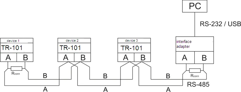
RS-485 as an interface standard has found extensive industrial application; it provides for establishing networks with node count of up to 247 and data transfer at distance of up to 1200 m. With use of duplicators, the number of nodes and the transmission distance can be increased. All network devices are connected in a serial bus (Figure A1). To maintain the reliable operation of transmitters/receivers and to eliminate interference impact, the communication line ends must be equipped with a terminating resistor of impedance Rсогл = 120 Ohm that is connected immediately to the device terminals (see Figure A1).
Figure A1 – RS-485 Network Connection Diagram 2 Remote Control for Power RelaysSection titled “2 Remote Control for Power Relays”By installation the value If the channel working with two level action and labeled to control register value 0 or 1 is possible to switch on or switch off prorated power relay. If the channel working with PID regulation and labeled to control register value 0 or 100 is possible to manage capacity plug into correspondent relay (pos. 3.2.6.6 of manual). If the mode “Remote management of power relay” is switched on TR-101 continuous working in usual mode. Exception is the fact that management of power relay is passed to operator. 3 Data Exchange Adjustment Through Interface RS-485Section titled “3 Data Exchange Adjustment Through Interface RS-485”Data exchange adjustment is realized by parameters:
Device TR-101 has following fixed exchange parameters not shown at the indicator:
4 Data Exchange Through Interface RS-485Section titled “4 Data Exchange Through Interface RS-485”4.1 Connection SetupSection titled “4.1 Connection Setup”Working through interface RS-485 it should be done relevant connection (p. 1 of Appendix A) and set the value of net parameters (p. 3 of Appendix A). 4.2 Network MasterSection titled “4.2 Network Master”For organization data exchange online through interface RS-485 necessary have net Master. The main function of this device is to activate data exchange between sender and recipient. TR-101 may work at Slave mode by ModBus RTU protocol. 4.3 ModBus ProtocolSection titled “4.3 ModBus Protocol”ModBus is the open network protocol that was developed by company Modicon. Protocol description available at website www.modbus.org. Register addresses of program parameters are shown in Table 7.1 of the manual. Check list of supported functions (Modbus) is shown in Table A1. Additional registers and their functions are shown in Table A2. Supported Modbus FunctionsSection titled “Supported Modbus Functions”Table A1 – Supported Modbus Functions
Additional RegistersSection titled “Additional Registers”Table A2 – Additional Modbus Registers Device IdentificationSection titled “Device Identification”
Status Register (Address 2)Section titled “Status Register (Address 2)”
Emergency Register (Address 3)Section titled “Emergency Register (Address 3)”
Temperature RegistersSection titled “Temperature Registers”
Relay Control RegistersSection titled “Relay Control Registers”
Reserved RegistersSection titled “Reserved Registers”
|
| | ||||||||||||||
|---|---|---|---|---|---|---|---|---|---|---|---|---|---|---|
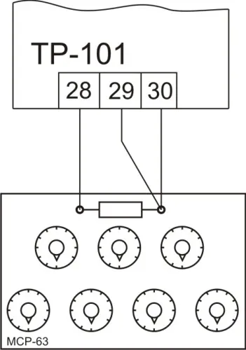
Appendix B: Device Adjustment1 General InstructionsSection titled “1 General Instructions”Adjustment of instrument must be done by qualifying specialists of metrological service if the measurement errors of input parameters are more than settled value. Before this operation necessary to check parameter set value 2 Adjustment of Instrument TR-101Section titled “2 Adjustment of Instrument TR-101”
Figure B.1 – TR-101 Adjustment Setup 2.1 Wire Resistance RequirementsSection titled “2.1 Wire Resistance Requirements”Resistance of wires should be equal in a line to each other and everyone should not exceed size 15 Ohm. 2.2 Resistance Box ConnectionSection titled “2.2 Resistance Box Connection”Plug into device input resistance box (instead of sensor) with accuracy class at least 0.05 (for example MSR-63) on three wire line (Figure B.1). Fix at resistance box the following values depending on sensor type:
2.3 Verification ProcedureSection titled “2.3 Verification Procedure”
2.4 Characteristic Shift AdjustmentSection titled “2.4 Characteristic Shift Adjustment”Fix parameter value Test accuracy of settled value: without changing the resistance, wait till the device passes into temperature mode and be sure that its indications are 0±1 °С. |