Novatek-Electro RPM-416 Documentation
https://www.overvis.com/docs/en/rpm-416/
2026-07-30
| |
|---|
Novatek-Electro RPM-416
The RPM-416 is a microprocessor-based data logger manufactured by NOVATEK-ELECTRO LTD. It is designed for electrical parameters measuring, monitoring, and data archiving with support for expansion modules and network connectivity. Key FeaturesSection titled “Key Features”
Input ChannelsSection titled “Input Channels”
Common Use CasesSection titled “Common Use Cases”
DocumentationSection titled “Documentation”
Technical ReferenceSection titled “Technical Reference”
ResourcesSection titled “Resources”
SupportSection titled “Support”
|
| | |||||||||||||||||||||||||||||||||||||||||||||||||||||||||||||||||||||||||||||||||||||||||||||||||||||||||||||||||||||||||||||||||||||||||||||||||||||||||||||||||||||||||||||||||||||||||||||||||||||||||||||||||||||||||||||||||||||||||||||||||||||||||||||||||||||||||||||||||||||||||||||||||||||||||||||||||||||||||||||||||||||||||||||||||||||||||||||||||||||||||||||||||||||||||||||||||||||||||||||||||||||||||||||||||||
|---|---|---|---|---|---|---|---|---|---|---|---|---|---|---|---|---|---|---|---|---|---|---|---|---|---|---|---|---|---|---|---|---|---|---|---|---|---|---|---|---|---|---|---|---|---|---|---|---|---|---|---|---|---|---|---|---|---|---|---|---|---|---|---|---|---|---|---|---|---|---|---|---|---|---|---|---|---|---|---|---|---|---|---|---|---|---|---|---|---|---|---|---|---|---|---|---|---|---|---|---|---|---|---|---|---|---|---|---|---|---|---|---|---|---|---|---|---|---|---|---|---|---|---|---|---|---|---|---|---|---|---|---|---|---|---|---|---|---|---|---|---|---|---|---|---|---|---|---|---|---|---|---|---|---|---|---|---|---|---|---|---|---|---|---|---|---|---|---|---|---|---|---|---|---|---|---|---|---|---|---|---|---|---|---|---|---|---|---|---|---|---|---|---|---|---|---|---|---|---|---|---|---|---|---|---|---|---|---|---|---|---|---|---|---|---|---|---|---|---|---|---|---|---|---|---|---|---|---|---|---|---|---|---|---|---|---|---|---|---|---|---|---|---|---|---|---|---|---|---|---|---|---|---|---|---|---|---|---|---|---|---|---|---|---|---|---|---|---|---|---|---|---|---|---|---|---|---|---|---|---|---|---|---|---|---|---|---|---|---|---|---|---|---|---|---|---|---|---|---|---|---|---|---|---|---|---|---|---|---|---|---|---|---|---|---|---|---|---|---|---|---|---|---|---|---|---|---|---|---|---|---|---|---|---|---|---|---|---|---|---|---|---|---|---|---|---|---|---|---|---|---|---|---|---|---|---|---|---|---|---|---|---|---|---|---|---|---|---|---|---|---|---|---|---|---|---|---|---|---|---|---|---|---|---|---|---|---|---|---|---|---|---|---|---|---|---|---|---|---|---|---|---|---|---|---|---|---|---|---|---|---|---|---|---|---|---|---|---|---|
RPM-416 Operating Manual
NOVATEK-ELECTRO LTD Intelligent industrial electronic MICROPROCESSOR-BASED DATA LOGGER RPM-416 OPERATING MANUAL Quality control system on the development and production complies with requirements ISO 9001:2015 Dear customer, Company NOVATEK-ELECTRO LTD. thanks you for purchasing our devices. You will be able to use properly the device after carefully studying the Operating Manual. Keep the Operating Manual throughout the service life of the device. UKRAINE, Odesa — www.novatek-electro.com IT IS NOT ALLOWED WATER PENETRATION ON TERMINALS AND INTERNAL ELEMENTS OF THE DEVICE. During operation and maintenance the regulatory document requirements must be met, namely:
Installation, adjustment and maintenance of the device must be performed by qualified personnel having studied this Operating Manual. The data logger connection, setting and maintenance should be made only by authorized personnel who have studied this operating manual. While repair work, maintenance work, installation work it is necessary to disconnect the data logger and incoming measuring lines from the power supply. The device is safe for operation under observing the rules of exploitation. This operation manual is intended for description, principle of work, construction, mode of work and maintenance of the microprocessor-based data logger RPM-416 (further in text as «data logger», «RPM-416» or «device»). The device meets the requirements of the following:
Harmful substances, in more than allowed concentration, are not available. Terms and AbbreviationsSection titled “Terms and Abbreviations”
1 PurposeSection titled “1 Purpose”1.1 Device’s PurposeSection titled “1.1 Device’s Purpose”Data logger RPM-416 is a microprocessor-based device intended for electrical parameters measuring and monitoring on the data logger display as well as data archiving. The data archiving is made on the removable memory card (SD / MMC), which can be later analyzed by software program RPM-416 Data Analysis (the program can be found on website www.novatek-electro.com), installed on the standard or portable PC. Data files have extension “RDF”. Data logger RPM-416 has an inbuilt real time clock with power from a lithium-type battery. RPM-416 can be connected to Ethernet network via standard 10Base-T or 100Base-T. In this case simultaneously with data recording to memory card, the RPM-416 configuration and data transmitting to the PC is possible. RPM-416 can connect to the system Overvis (monitoring and remote control www.overvis.com). The main possibilities of the data logger:
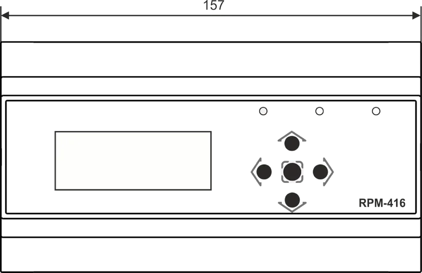
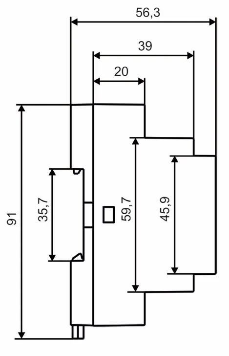
1.2 Controls, Overall and Installation DimensionsSection titled “1.2 Controls, Overall and Installation Dimensions”1.2.1 Overall and Installation DimensionsSection titled “1.2.1 Overall and Installation Dimensions”
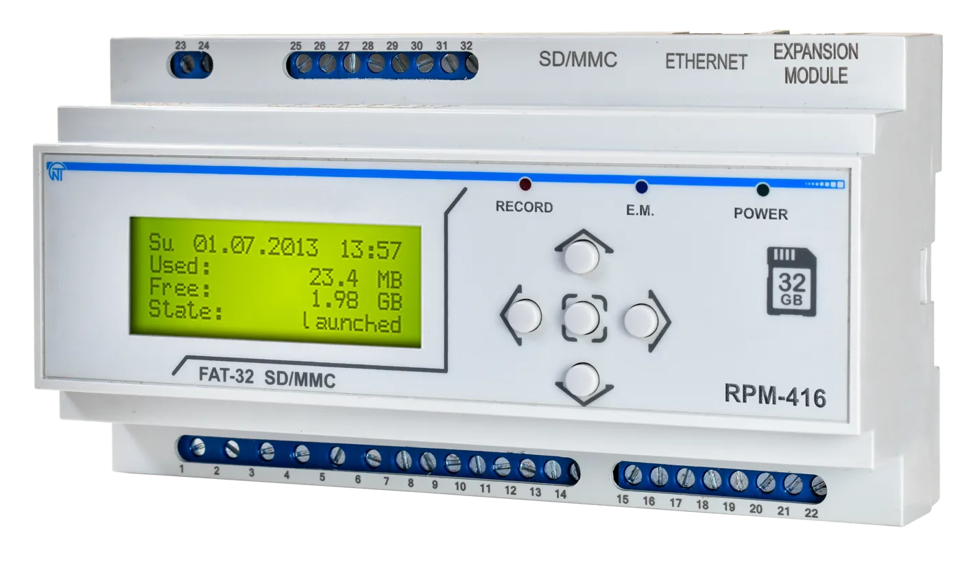
Figure 1.1 – Data logger design with overall and fixing dimensions 1.2.2 ControlsSection titled “1.2.2 Controls”On the data logger front panel there are located the elements of control (five-button keyboard) and indication (LED symbolic display), Fig. 1.2. With the help of the keyboard are made all the settings of the data logger operation parameters and initiation of incoming signals values recording to the memory card. The current values of the data logger operation, the values of incoming signals and data logger state information are shown on the display.
1 – Display (yellow-green indication) 2 – LED indicator RECORDING (light on – when the data recording on the memory card is initiated, light off – when the data recording on the memory card is finished, flare up – when the data recording on the memory card is paused, flickering – when there is at least one error in the data logger operation) 3 – Button ▲ (up) is used for moving the indicator upwards or for increasing parameter value 4 – LED indicator E.M. (E.M. light on – when at least one expansion module is connected, flickering – when there is data transmitting between expansion modules, light off – when the expansion modules are not connected) 5 – Button ◙ (enter) is used for value entry approval or menu item choice 6 – LED indicator POWER (light on – when the power is on, light off – when the power is off) 7 – Button ► (right) is used for moving the indicator to the right 8 – Button ▼ (down) is used for moving the indicator downwards or for decreasing the parameter value 9 – Button ◄ (left) is used for moving the indicator to the left Figure 1.2 – The data logger controls 1.3 Working ConditionsSection titled “1.3 Working Conditions”The data logger RPM-416 is intended for working in the following conditions:
2 Completeness of SetSection titled “2 Completeness of Set”Delivery set is given in Table 2.1. Table 2.1 – Delivery Set
3 Technical Specification of RPM-416Section titled “3 Technical Specification of RPM-416”3.1 Basic Technical FeaturesSection titled “3.1 Basic Technical Features”The basic technical features of RPM-416 are shown in Table 3.1. Table 3.1 – Basic technical features
3.2 Input CharacteristicsSection titled “3.2 Input Characteristics”Input characteristics of RPM-416 are shown in Table 3.2. Measurement error is shown in ± % of scale value. Table 3.2 – Inputs characteristics Voltage Input (3 channels)Section titled “Voltage Input (3 channels)”
Current Input (4 channels)Section titled “Current Input (4 channels)”
Working Power Input* (3 channels)Section titled “Working Power Input* (3 channels)”
* Power input has no physical connection terminals, the power parameters are calculated on basis of measured values of voltage and current. Temperature Input (2 channels)Section titled “Temperature Input (2 channels)”
Analog Voltage Input 0–10 V (1 channel)Section titled “Analog Voltage Input 0–10 V (1 channel)”
Analog Current Input 0–20 mA (1 channel)Section titled “Analog Current Input 0–20 mA (1 channel)”
Digital Input (4 channels)Section titled “Digital Input (4 channels)”
4. Design and Operation PrincipleSection titled “4. Design and Operation Principle”4.1 DesignSection titled “4.1 Design”RPM-416 is constructively made in a plastic case intended for fixing on DIN-rack 35 mm, case dimensions (91×157×56.3 mm) 9 modules of S type. The case is made of crashworthy, self-extinguishing material. 4.2 Operation PrincipleSection titled “4.2 Operation Principle”The data logger operation principle is based on measuring values from all sensors connected to the data logger inputs, accumulating the data in the data logger internal memory and data recording to the external memory storage – memory card (SD / MMC). 4.3 Real Time ClockSection titled “4.3 Real Time Clock”The data logger is equipped with an inbuilt real time clock which is powered (in case of main power failure) from an inbuilt backup power cell – lithium type battery. The power from the backup supply is sufficient for continuous operation of the real time clock during 10 years (at temperature 25 ºС). In case of data logger operation at temperatures on the limits of the working range, the working period of the clock decreases. 5. ConnectionSection titled “5. Connection”5.1 Preparing for ConnectionSection titled “5.1 Preparing for Connection”
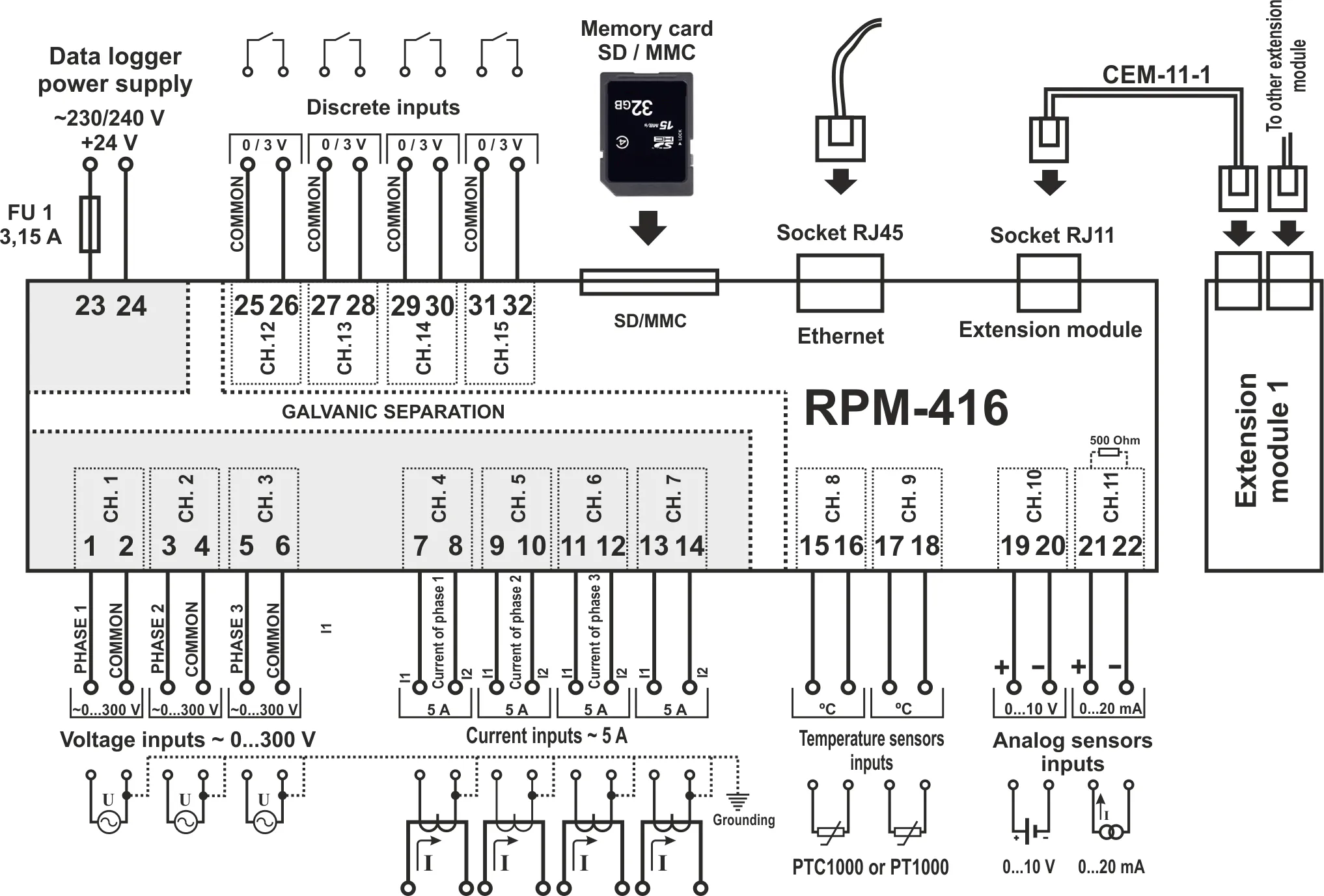
5.2 General InstructionsSection titled “5.2 General Instructions”If the temperature of the device after transportation or storage differs from the environment temperature at which it is expected to operate, then before connection to electric mains keep the device under operating conditions within two hours (because the device elements may have moisture condensation). To ensure the reliability of electrical connections, one should use flexible (stranded) wires with insulation for a voltage not less than 450 V. Recommended cable cross-sections to measure current is within 1.5 – 2.5 mm², for the rest of connections it is within 0.75 – 2.5 mm². The wire ends should be cleared from insulation for 5±0.5 mm and clamped by a sleeve lug. Fixation of wires should exclude mechanical damages, twisting and abrasion of wires’ insulation. When reducing the tightening torque, the junction point is heated, terminal block may be melted and wire can burn. If you increase the tightening torque, it is possible to have thread failure of terminal block screws or the compression of the connected wires. For reduction of electric field influence, the installation of “data logger-sensor” lines should be made as a separate route (or several routes). The routes should be located separately from power cables as well as away from cables which make high frequency and impulse noise. The routes should be planned in such a way that the length of signal lines is minimal. The connection of expansion modules is made with the help of cable CEM-11-1 (see section 5.4, the cable is supplied along with every expansion module). The connection of the data logger to Ethernet network is carried out by the cable made according to the standard ANSI EIA TIA 568B (see section 5.5, the cable is supplied along with the data logger). During use of backup power supply, the connection is made to the same terminals as the main power source. It is necessary to have a scheme ABI (Automatic Backup Input) for switching from the main power source to the backup power supply. For ensuring continuous data recording, ABI should switch power supply to backup source within a period not more than 0.5 sec. 5.3 Connection DiagramSection titled “5.3 Connection Diagram”The connection of RPM-416 is made according to the scheme shown in Figure 5.1. In order to improve safety in the power circuit, it is recommended to install a fuse with nominal value of 3.15 A.
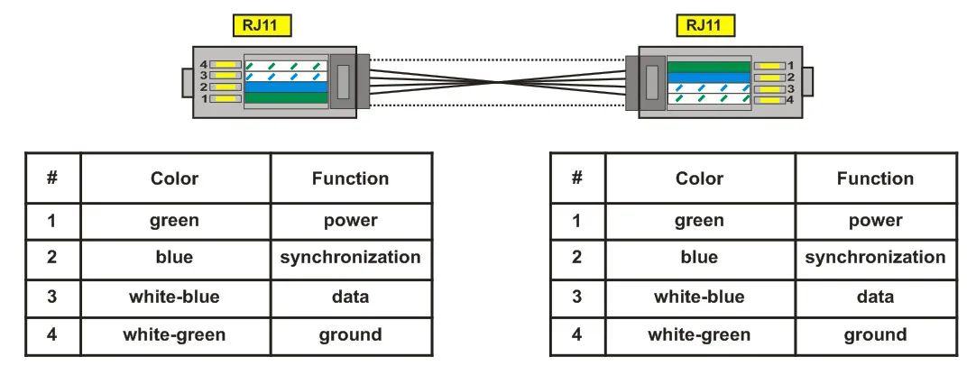
FU1 – The fuse (circuit breaker) for current 3.15 A Figure 5.1 – Connection diagram of RPM-416 5.4 Connection of Expansion ModulesSection titled “5.4 Connection of Expansion Modules”Up to 4 expansion modules can be connected to the data logger at the same time. At attempt to add more than the specified quantity of modules, the RPM-416 stops perceiving all modules and switches them off. The expansion modules installation should be carried out with the data logger power being switched off. The module connection should be made with cable CEM-11-1 (not supplied with the data logger). The number indication of cable CEM-11-1 terminals is shown in Figure 5.2.
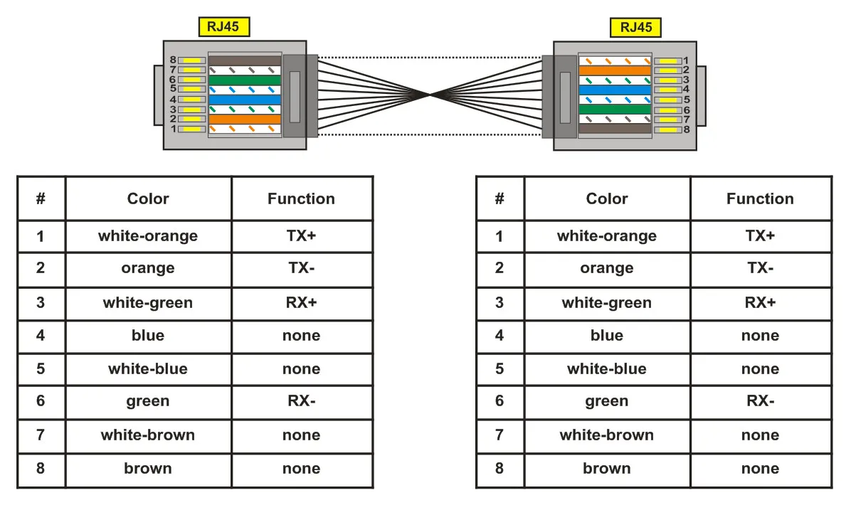
Figure 5.2 – Number indication of cable CEM-11-1 One end of the cable is connected to the socket RJ11 located in the data logger as shown in Figure 5.1, the other end of the cable is connected to the socket RJ11 located in the expansion module. The connection linkage is made automatically after power input to the data logger. The cable CEM-11-1 is supplied with every expansion module. 5.5 Connection to Ethernet NetworkSection titled “5.5 Connection to Ethernet Network”Connection of the RPM-416 to Ethernet network is carried out via the cable made according to the standard ANSI EIA TIA 568B category Cat.3 and higher (supplied with the device). The numeral indication of such cable is shown in Figure 5.3.
Figure 5.3 – Numeral indication of cable for connection to Ethernet One end of the cable is connected to the socket RJ45 located in the data logger as shown in Figure 5.1, the other end of the cable is connected to the socket of network adapter located in the PC or other network device. LED indicators, located near the socket RJ45 indicate:
For communication connection via Ethernet interface, the data logger and PC should be in the same IP-subnet. Programming of the RPM-416 while connected to Ethernet network is described in Appendix A. Programming of the RPM-416 while connected to Internet network is described in Appendix B. 6. Scope of Intended UseSection titled “6. Scope of Intended Use”6.1 The Use of Data Logger RPM-416Section titled “6.1 The Use of Data Logger RPM-416”6.1.1 InitializationSection titled “6.1.1 Initialization”After supply of the power to the data logger, the process of initialization takes place. The LED indicator POWER (Fig. 1.2 item 6) lights up and on the display (Fig. 1.2 item 1) there is a message shown in Figure 6.1. 6.1.2 Main ScreenSection titled “6.1.2 Main Screen”After completion of initialization, the main screen will be shown on the display. The view depends on whether a memory card is installed or not. Figure 6.2 shows both variants of main screen views. With memory card Without memory card In the first line, the current date and time is shown in form of DD dd mm yyyy HH:MM, where:
In the second and third lines there is information of occupied and free space on the memory card (“Used” – Used space and “Free” – free space). In case there is no memory card installed, the display shows the message “Memory card is not installed”. In the fourth line, the main menu items of the data logger control are shown. The choice of the menu items is made by buttons ◄ (left) or ► (right) (the selected item is illuminated by indicator ”◄ ►”), confirmation is made by pressing the button ◙ (enter). The main menu items of the Data logger:
6.1.3 Main Screen Menu Items DissimulationSection titled “6.1.3 Main Screen Menu Items Dissimulation”If during 10 seconds no button on the front panel was pressed, the menu items of data logger control will be dissimulated and instead of them there will be shown the current state of the data logger (Fig. 6.3). With memory card and recording process stopped Without memory card and recording process stopped With memory card and recording process started In order to restore the indication of menu items of data logger control, it is enough to press any button on the front panel of the data logger. The indication of the data logger state will be dissimulated and the control menu items will be shown instead (Fig. 6.2). 6.1.4 Starting and Stopping Data RecordingSection titled “6.1.4 Starting and Stopping Data Recording”To start the process of data recording to the memory card, select with buttons ◄ (left) or ► (right) the menu item “Start”, then by pressing the button ◙ (enter) confirm the choice. The data logger display will show a message confirming the beginning of the recording process (Fig. 6.4) and LED indicator RECORDING will be on (Fig. 1.2 item 2). After 3 seconds the main screen (Fig. 6.4) will be shown on the data logger display. On the main screen there will be alternatively shown information of the free and occupied space on the memory card (Fig. 6.4 – Main screen variant 1), as well as the name and size of the last recorded file (Fig. 6.4 – Main screen variant 2). Message of data recording process start Main screen (variant 1) Main screen (variant 2) If there are no mistakes in configuration, the data logger creates a new file in the following path “RPM-416\2014\JUL\03\FILE0001.RDF”, where:
When the file size reaches the user defined limit (32 KB – 512 MB), the data logger automatically creates a new file with the following name “FILE0002.RDF”. When the file name reaches the maximum (“FILE9999.RDF”), the recording process will be terminated and on the data logger display there will be a message about an error shown in Figure 6.5. The LED indicator RECORDING (Fig. 1.2, item 2) will start flickering indicating that there is a mistake in the data logger operation. For confirming the error, press the button ◙ (enter) (Fig. 1.2, item 5). The LED indicator RECORDING (Fig. 1.2, item 2) will start flickering indicating that the recording process is paused. Depending on the recorded readings selected by user (the maximal number of recorded readings at the same time is 20), one data block size being recorded to the memory card for 20 readings is 88 bytes. The stream of recorded data at discretion 1 ms for 20 readings is:
The stream of recorded data at discretion 1 s for 20 readings is:
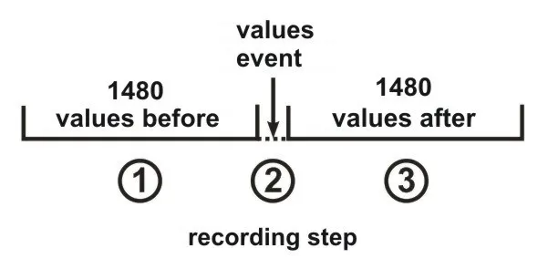
To stop the recording process, on the main screen of the data logger (Fig. 6.6) by buttons ◄ (left) or ► (right) select menu item STOP, and by button ◙ (enter) confirm the selection. On the display there will be a message in which you need to confirm the stop of the recording process. Main screen Screen of confirming the recording process stop “Yes” / “No” For confirming the recording process stop, select by buttons ◄ (left) or ► (right) indicator position “YES”, and by button ◙ (enter) confirm the selection. The data logger will stop recording data to the memory card, the LED indicator RECORDING (Fig. 1.2, item 2) will light off and the display will look as shown in Figure 6.2 (with memory card). After locating the indicator in position “NO”, the data logger will continue recording and there will be on the display the main screen resulted in Figure 6.6. If during the recording the memory card is full and has no free space, then depending on the selected type of recording (“Until memory” or “The ring”): “Until memory” – there will be a message about an error on the display (resulted in Figure 6.7), and the recording automatically stops. “The ring” – there will be a message on the display about the deleting of old files (resulted in Figure 6.8). The data logger makes searching and deleting the old files in order to free some space on the memory card for creating a new file. 6.1.5 Data Recording at EventSection titled “6.1.5 Data Recording at Event”RPM-416 can make data recording at event (this mode is described in the Setting of Event Recording Mode section). If the data recording at event is switched on, the values measured by the data logger are continuously being recorded in temporary buffer storage with a user defined periodic sequence (parameter “Discreteness” at default is 1 ms). Maximal length of temporary buffer storage is 1480 recordings. The buffer storage is sequential data, where the reading is performed from “beginning” and recording is made to “end”. When the buffer is full, the data deleting is performed from “beginning” and the new data is located in “end”. In RPM-416 there are five available sources of events, every of which can be set individually to any of the data logger inputs. Until the event happens, the data logger continuously checks the measured values with the up and down limits specified by the user during the event setting. If the measured value is higher (up limit) or lower (down limit), the event is generated. After the event happens, the data recording is performed in three stages, as shown in Figure 6.9.
Figure 6.9 – Data recording at event (stages) At the first stage, the values accumulated in the temporal buffer storage are recorded. At the second stage, the value generated the event is recorded. At the third stage, after event changed values are recorded. After completion of all stages of recording, the data logger goes to stand-by mode waiting for a new event. The number of values recorded before and after the event is set by parameters “Points before” and “Points after” in the menu of events setting (see Setting of Event Recording Time). If the limit of the event is set for a single recording (“ONCE”, see Setting of Upper and Lower Thresholds), then there will be no generating of the next event if the measured value is lower (up level) or higher (down level) of specified limits. If the event limit is set on continuous recording (“LONG”, see Setting of Upper and Lower Thresholds), then after the event happens the data recording will continue, until the measured value is higher (up level) or lower (down level) of specified limits. 6.1.6 The Main Menu of the Data LoggerSection titled “6.1.6 The Main Menu of the Data Logger”For entering the data logger main menu: on the main screen by buttons ◄ (left) or ► (right) select item “MENU/МЕНЮ”, and by button ◙ (enter) confirm the selection. If the password was set before, the data logger asks to enter the password (Fig. 6.10 Screen of password entering). Screen of password entering Message about an error of password entering The password entering is carried out in the following manner: by buttons ◄ (left), ► (right), ▲ (up) and ▼ (down) make the selection of one digit of password (the selected digit is illuminated by cursor), and by button ◙ (enter) confirm the selection. Sign ”^” indicates the digit which is selected at the moment. To delete one digit of the password, set a cursor in position “c” (for example in case of error selection). After completion of password selection, set a cursor in position “ОК” and press the button ◙ (enter). If the password is not correct, there will be a message about the mistake on the display as shown in Fig. 6.10. If the password is correct or if the password was deactivated by the user, there will be a list of main menu available items on the display of the data logger. The screen of the data logger main menu is shown in Figure 6.11. The selection of the menu items is made by buttons ▲ (up) or ▼ (down), the confirmation of the selection is made by button ◙ (enter). To escape from the main menu, press the button ◄ (left). If there were made changes in settings, the data logger asks to save them by the message on the display shown in Figure 6.12. Otherwise on the data logger display there will be the main screen (Fig. 6.2). To confirm the saving, by button ◄ (left) locate the cursor in position “YES” and press the button ◙ (enter). The data logger makes saving of the settings in nonvolatile memory and the display will show the main menu (Fig. 6.2). To cancel the saving of the settings, by button ► (right) put the cursor in position “NO” and press the button ◙ (enter). The data logger will load the settings from the nonvolatile memory and the display will show the main menu (Fig. 6.2). The full list of items of the main menu is described in Chapter 7 “The setting of the data logger RPM-416”. 6.1.7 The Review of Measured ValuesSection titled “6.1.7 The Review of Measured Values”To review the measured values: on the main screen by buttons ◄ (left) or ► (right) select item “Measuring”, and by the button ◙ (enter) confirm the selection. The display shows the first of a list of available channels and the measured values. The screen of measured values for channel 1 is shown in Figure 6.13. The first three lines display measured values available for this channel. The fourth line displays the menu item “BACK” navigation direction symbols and channel number (“CH01”). Shifting to the next open channel is made by pressing the button ◄ (left) or ► (right), and by buttons ▲ (up) or ▼ (down) you can scroll through the list of available measuring. To escape from the screen of measured values, press the button ◙ (enter). The display will go to initial view (Fig. 6.4 – Main screen). Table 6.1 – The list of channels with corresponding names of measured values
6.1.8 Error Message ConfirmationSection titled “6.1.8 Error Message Confirmation”In the process of the data logger work there can happen different errors (real time clock error, data exchange failure, settings failure etc.). The total list of possible errors is presented in Table 6.2. If an error takes place, it is shown on the display of the data logger. The LED indicator RECORD begins to blink. The error message will be on the display until all errors are confirmed. Screen with an error message is shown in Figure 6.14. In the first line there is a description of error and its code “ERROR # 6!”. As well in the first line there is a current number of error and total quantity of errors “1/3”. In the second, third and fourth lines there is an error text. By buttons ▲ (up) and ▼ (down) you can scroll the list of errors and by button ◙ (enter) you can confirm the current error. If all the errors are confirmed by user but the data logger continues to state the active errors, the LED indicator RECORD continues to flicker. After 20 seconds the data logger will again show the active errors on the display. If there are no active errors and the user confirmed all the errors, LED indicator RECORD lights off – in case the recording is stopped, lights on – in case the recording continues, or flickers – in case the recording is paused. Table 6.2 – Total list of possible errors of the data logger
Critical errors (require data logger restart):
6.2 Use of HTTP Server (Web-interface)Section titled “6.2 Use of HTTP Server (Web-interface)”For access to Web-interface of the data logger, a PC with an installed Web-browser is required. In the Web-browser, enter the IP-address of the data logger (factory setting 192.168.0.2) and press the button to access this address. On the PC screen there will be a welcome page of the data logger RPM-416 with offer to enter the password (factory setting “admin”). After the password entering and pressing the button “Enter”, if the password is correct, there will be the main screen of the data logger. If the password is not correct, there will be a password error message on the PC display. On the main screen you can monitor the current state of the data logger, make settings, control and restart. After resetting RPM-416, press the button “Save setting”. The entered settings will be checked. In case there are no errors in the setting parameters, they will be saved in nonvolatile memory of the data logger. In case there are some errors in the setting parameters, they will not be saved. After the completion of the work with Web-interface, press the button “Exit”. The main page will be closed and the welcome and password page will be opened. If there is no activity of the user during 5 minutes (this period is specified by the user, see Setting of HTTP Connection Timeout), the data logger automatically closes the communication. In this case it is necessary to enter IP-address of the data logger and password again. 6.3 Use of Modbus TCP ServerSection titled “6.3 Use of Modbus TCP Server”Connection protocol Modbus TCP enables connecting the data logger to the network organized by standard Ethernet. The use of the data logger in network enables to perform the following operations:
While connecting to the data logger, the access to the command registry and recording function is blocked (reading function is not blocked). To unblock the access to the command data logger and recording function, write in registries 51-63 the modbus password in ASCII symbols (factory default “admin”). In unused registries, there should be written zero values (0x0000). In case the modbus password is correct, the data logger will unlock the access to the command registry and recording function. The data logger control is carried out via the command registry (see Modbus Registers Reference). After completing data logger resetting, carry out the command of recording in the nonvolatile memory (0x472C). For the changes to take place, the data logger should be restarted (0xF2C5). If the functions of recording and register of commands are not used for a long period of time, block the access to them by writing in registries 51-63 values differing from the modbus password (for example, 0). If there is no data exchange for 60 seconds (time is set by the user, see Setting of Modbus TCP Connection Timeout), the data logger automatically breaks the connection with the client. In the data logger, all values with a decimal point are converted to whole numbers. That’s why while processing the data, it is necessary to use additional mathematic operations. To the request of reading the value with a dot (for example, 1.000) the data logger will return the whole number value 1000, for adjusting to the correct format it is necessary to divide the number by 1000. Before recording the value with a dot (for example, 1.000) it is necessary to bring the value to the whole number by multiplying by 1000, then make recording of the value in the data logger. The coefficient of changing to whole number is defined by the number of digits after the dot (1.0 – 10; 1.00 – 100; 1.000 - 1000). The types of parameters and their names are given in the Parameter Types table. The list of supported Modbus functions is in the Supported Functions table. The command registry address is in the Command Registry section. Addresses of additional registries are in the System Registries section. Addresses of the registers of the measured parameters of the base channels are given in the Base Channel Registers section. Register addresses for expansion modules are in the Expansion Module Registers section. Addresses of programmable parameters are in the Programmable Parameters section. For the complete Modbus register map including supported functions, command codes, parameter types, system registries, and channel addresses, see Appendix E: Modbus Registers Reference. 6.4 Use of FTP ServerSection titled “6.4 Use of FTP Server”File transfer protocol FTP uses the double connection. One channel is a control channel through which the commands from the data logger come in and responses go out (default TCP-port 21), and via the second channel comes data communication (TCP-port is defined by the data logger by random choice). Use of FTP protocol enables via TCP-networks to receive remote files recorded by the data logger on the memory card. Files receiving is carried out with the help of program “RPM-416 Data Analysis” or any other software which supports file receiving via FTP. In the data logger, server FTP operates in passive mode (waiting for the client’s connection). At connection to the data logger via FTP it is necessary to write the name of the user “ftp” and password (factory default “admin”). Supported FTP commands:
If there is no data exchange during 300 seconds (time period can be set by the user, see Setting of FTP Connection Timeout), the data logger automatically breaks the connection with a client. 6.5 Use of Overvis ClientSection titled “6.5 Use of Overvis Client”Overvis is a system for monitoring, visualization and remote control of technological processes. Overvis enables:
More detailed information can be found at the official website www.overvis.com. Overvis system acts as a collection server of data from the recording system and other devices connected simultaneously, and it provides access to data in real time only with the permission of the owner of the recording system. Factory settings of the recording system are prepared to connect to the server of Overvis, in this case the Overvis client in the recording system is disabled and should be enabled manually by the user. To connect the recording system to the system of Overvis it is required:
6.6 Inserting and Pulling Out of the Memory CardSection titled “6.6 Inserting and Pulling Out of the Memory Card”Insert the memory card in the slot situated on the side wall of the data logger, as shown in Figure 5.1 and press it till there is a click. In order to pull the memory card out, press it till a click and release it – the memory card will go out from the slot about 3-5 mm, after that you can pull it out. During inserting and pulling out of the memory card do not use much effort. 6.7 RPM-416 Data Analysis Software InstallationSection titled “6.7 RPM-416 Data Analysis Software Installation”For proper work of the software on the computer there should be installed Operational System Windows Vista or Windows 7/8/10/11. The installation is initiated by starting the installation file “rpm416da_setup.exe” (not included in the supply scope). After starting of the installation, the program performs the installation guided by the instructions of installation master. If the previous version of the program has been already installed on the computer it should be deleted before a new installation. The latest version of the program is available on the web site https://novatek-electro.com in section “Software”. To delete the program, you should use Windows master of installation and deleting. 6.8 Installation and Connection of Software for Memory Card-ReaderSection titled “6.8 Installation and Connection of Software for Memory Card-Reader”The procedure and installation of software for memory cards reading depends on the model and manufacturer of the device. All installation instructions are provided in the card reader manual. 6.9 Review of the Recorded DataSection titled “6.9 Review of the Recorded Data”Pull out the memory card from the data logger (pulling out of the memory card is described in item 6.6) and insert it in the card reader on the PC. Review and analysis of the data is carried out with program software “RPM-416 Data Analysis” installed on the PC (installation of the software is described in item 6.7). Program “RPM-416 Data Analysis” enables to make the analyses of data, to compare it (in form of numeral information or diagrams) and output the results of the analysis for printing. The program can also perform a remote configuration of the data logger and monitor its operation in real time mode via protocol Modbus TCP. 7. Setting of the Data Logger RPM-416Section titled “7. Setting of the Data Logger RPM-416”The description of settings is based on the factory parameters settings. The parameters are saved in the nonvolatile memory (period of storage is not less than 10 years). For restoring the main menu of the RPM-416, perform the actions described in the Main Menu of the Data Logger section. Main Menu ItemsSection titled “Main Menu Items”
The selection of the menu items is performed by buttons ▲ (up) or ▼ (down) (the selected item is underlined by the cursor), confirmation of the selection is made by pressing the button ◙ (enter). For escape from the menu, press the button ◄ (left). For detailed settings information, please see Appendix D: Settings Reference. 8. MaintenanceSection titled “8. Maintenance”8.1 Safety PrecautionsSection titled “8.1 Safety Precautions”8.2 Qualified PersonnelSection titled “8.2 Qualified Personnel”Maintenance of the device must be performed by qualified service personnel. 8.3 Maintenance FrequencySection titled “8.3 Maintenance Frequency”Recommended frequency of maintenance is every six months. 8.4 Maintenance ProcedureSection titled “8.4 Maintenance Procedure”
9. Service Life and Manufacturer WarrantySection titled “9. Service Life and Manufacturer Warranty”9.1 Service LifeSection titled “9.1 Service Life”The lifetime of the data logger is 10 years. Upon expiration of the service life, contact the manufacturer. 9.2 Shelf LifeSection titled “9.2 Shelf Life”Shelf life is 3 years. 9.3 Warranty PeriodSection titled “9.3 Warranty Period”Warranty period of the RPM-416 operation is 5 years from the date of sale. During the warranty period of operation (in the case of failure of the data logger) the manufacturer is responsible for free repair of the device. 9.4 Warranty Service LocationSection titled “9.4 Warranty Service Location”Warranty service is performed at the place of purchase or by the manufacturer of the device. 9.5 Post-Warranty ServiceSection titled “9.5 Post-Warranty Service”Post-warranty service of the data logger is performed by the manufacturer at current rates. 9.6 Repair ShippingSection titled “9.6 Repair Shipping”Before sending for repair, the data logger should be packed in the original or other packaging excluding mechanical damage. 10. Transportation and StorageSection titled “10. Transportation and Storage”The data logger in the original package is permitted to be transported and stored at the temperature from -45°C to +60°C and relative humidity of 80%. Manufacturer InformationSection titled “Manufacturer Information”“Novatek-Electro” Ltd. Website: www.novatek-electro.com Address: 59, Mykhailo Boltenko (Admiral Lazarev) str., Odesa, Ukraine, 65007 Phone:
AppendicesSection titled “Appendices”
|
| | ||||||||
|---|---|---|---|---|---|---|---|---|
Appendix A: Connection of the Data Logger to EthernetA.1 IP-addressingSection titled “A.1 IP-addressing”At communication of the device via Ethernet network over TCP/IP protocol, in order to distinguish the data transmitter and recipient, every device uses a special setting of IP-addressing. The device keeps in memory:
Subnet Configuration RulesSection titled “Subnet Configuration Rules”For correct communication of the devices in the subnet, observe the following provisions:
Gateway ConfigurationSection titled “Gateway Configuration”In most cases, a new device (for example, a router) which is connected to network already has connection with other networks. Often the addresses 192.168.0.1, 192.168.0.100 or 192.168.0.101 are reserved for it. In this case, other devices in the network receive IP-Address of this device as a gateway address. Indication of this address is not obligatory for communication between devices in the subnet and is used only for communication of devices of one subnet with devices in other subnets. Factory SettingsSection titled “Factory Settings”Table A.1 - Factory IP Settings
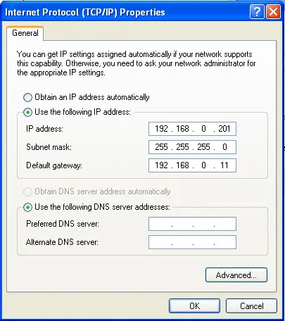
For the data logger communication with a client-device (and any other devices in the same subnet), the mask 255.255.255.0 and addresses starting with 192.168.0.x are used. The fourth byte of address can be any value in range 1–255, except 2. In case of indirect connection (between RPM-416 and client-device), and in a network with several devices, the address cannot be equal to any of the addresses of other devices in the subnet. A.2 Setting of Client-DeviceSection titled “A.2 Setting of Client-Device”Setting of addressing of client-device should be performed according to the documentation of this device and the software used in it. Example: Windows 7/8/10/11 ConfigurationSection titled “Example: Windows 7/8/10/11 Configuration”To configure a personal computer (PC) with Windows for direct connection to RPM-416 with factory settings:
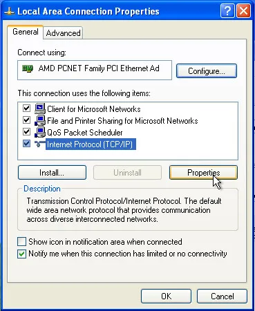
In the opened screen of connections, select the adapter which addressing should be changed. Many computers have only one adapter, which will be shown in this screen.
Fig. A.1 – Example of connection properties screen in Windows
Fig. A.2 – Example of protocol TCP/IPv4 properties screen in Windows After completing these steps, your PC should be able to communicate with the RPM-416 data logger. |
| |
|---|
Appendix B: Connection of the Data Logger to InternetRequirements for Internet ConnectionSection titled “Requirements for Internet Connection”For connection of the data logger to Internet, use the following recommendations:
Router ConfigurationSection titled “Router Configuration”At connection of the data logger via a router (routing gateway):
Accessing the Data Logger RemotelySection titled “Accessing the Data Logger Remotely”At addressing the data logger in Internet network, you should use the IP-Address obtained from the provider (your static public IP address). Common ports used by RPM-416:
Configure your router to forward these ports to the data logger’s internal IP address (192.168.0.2). Security ConsiderationsSection titled “Security Considerations”Security RecommendationsSection titled “Security Recommendations”
|
| | ||||||||||||||||||||||||||||||||||||||||||||||||||||||
|---|---|---|---|---|---|---|---|---|---|---|---|---|---|---|---|---|---|---|---|---|---|---|---|---|---|---|---|---|---|---|---|---|---|---|---|---|---|---|---|---|---|---|---|---|---|---|---|---|---|---|---|---|---|---|
Appendix C: RPM-416 Software Version HistoryThis appendix provides a complete history of firmware versions for the RPM-416 Data Logger. Version HistorySection titled “Version History”
Checking Your Firmware VersionSection titled “Checking Your Firmware Version”To check the current firmware version of your RPM-416:
Firmware UpdatesSection titled “Firmware Updates”For information about updating your RPM-416 firmware, please contact NOVATEK-ELECTRO technical support. |
| | ||||||||||||||||||||||||||||||||||||||||||||||||||||||||||||
|---|---|---|---|---|---|---|---|---|---|---|---|---|---|---|---|---|---|---|---|---|---|---|---|---|---|---|---|---|---|---|---|---|---|---|---|---|---|---|---|---|---|---|---|---|---|---|---|---|---|---|---|---|---|---|---|---|---|---|---|---|
Appendix D: RPM-416 Settings ReferenceThis appendix provides complete instructions for configuring all settings of the RPM-416 Data Logger. The description of settings is based on the factory parameter settings. Parameters are saved in nonvolatile memory (storage period is not less than 10 years). For restoring the main menu of the RPM-416, perform the actions described in the Main Menu of the Data Logger section of the Operating Manual. Main Menu ItemsSection titled “Main Menu Items”
The selection of menu items is performed by buttons ▲ (up) or ▼ (down) (the selected item is underlined by the cursor), confirmation of the selection is made by pressing the button ◙ (enter). To exit the menu, press the button ◄ (left). D.1 Setting of Date and Time (“Date and Time”)Section titled “D.1 Setting of Date and Time (“Date and Time”)”For setting the date and time it is necessary: in the main menu of the data logger by buttons ▲ (up) or ▼ (down) select the item “Date and time”, confirm the selection by pressing the button ◙ (enter). On the display of the data logger there will be the list of available menu items for setting the date and time:
By buttons ▲ (up) or ▼ (down) make the selection of the corresponding menu item, confirm the selection by pressing the button ◙ (enter). To restore the previous menu, press the button ◄ (left). D.1.1 Setting of Date (“Date”)Section titled “D.1.1 Setting of Date (“Date”)”At selection of this item on the display of the data logger there will be a screen of the date setting, resulted in the Figure D.1.1. On this screen the date is resulted in format “DDD dd.mm.yyyy”, where:
By buttons ◄ (left), ► (right), ▲ (up) and ▼ (down) make a selection of the necessary parameter (the selected parameter is highlighted by the cursor). For starting the changes in the parameter, it is necessary to press the button ◙ (enter), the selected parameter starts to blink. By buttons ▲ (up) or ▼ (down) change the value of the parameter. After completion it is necessary to press again the button ◙ (enter) – to escape from the mode of setting and saving of the changed parameter. The parameter stops blinking. In case of necessity repeat the same procedure with other parameters. To restore the previous menu, it is necessary by button ▼ (down) select the position “BACK” and press the button ◙ (enter). D.1.2 Setting of Time (“Time”)Section titled “D.1.2 Setting of Time (“Time”)”At selection of this item on the display of the data logger there will be a screen of the time setting, resulted in the Figure D.1.2. On this screen the time is resulted in format “HH:MM:SS CC”, where:
By buttons ◄ (left), ► (right), ▲ (up) and ▼ (down) make a selection of the parameter (the selected parameter is highlighted by the cursor). For starting the changes in the parameter, it is necessary to press the button ◙ (enter), the selected parameter starts to blink. By buttons ▲ (up) or ▼ (down) change the value of the parameter. After completion of change it is necessary to press the button ◙ (enter) again – to escape from the mode of setting and saving of the changed parameter. The parameter stops blinking. In case of necessity, repeat the same procedure with other parameters. To restore the previous menu, it is necessary by button ▼ (down) select the position “BACK” and press the button ◙ (enter). D.2 Setting of Base Channels (“Base Channels”)Section titled “D.2 Setting of Base Channels (“Base Channels”)”The data logger – is a multichannel device, which has different inputs (voltage, current, temperature, discrete inputs etc.) requiring individual setting. For channels setting it is necessary in the main menu by buttons ▲ (up) or ▼ (down) select the item “Channels”, confirm the selection by pressing the button ◙ (enter). On the display of the data logger there will be the list of available channels:
By buttons ▲ (up) or ▼ (down) make selection of necessary item of menu, confirm the selection by pressing the button ◙ (enter). To restore the previous menu, press the button ◄ (left). D.2.1 Setting of Voltage Channel (“Channel 1” (2 and 3))Section titled “D.2.1 Setting of Voltage Channel (“Channel 1” (2 and 3))”At selection of this item on the display of the data logger there will be a screen with a list of available items for setting the channel of voltage:
By buttons ▲ (up) or ▼ (down) make a selection of the necessary item, confirm the selection by pressing the button ◙ (enter). To restore the previous menu, press the button ◄ (left). Setting of Voltage Sensor (“Voltage sensor”)Section titled “Setting of Voltage Sensor (“Voltage sensor”)”At selection of this item on the display of the data logger there will be the screen of setting of voltage conversion ratio, resulted in the Figure D.2.1. On this screen you can set the voltage conversion ratio from 1.0 to 5000.0. By button ▲ (up) select the parameter “1.0” (the selected parameter is highlighted by the cursor). For starting the changes in the parameter, it is necessary to press the button ◙ (enter), the selected parameter starts to blink. By buttons ▲ (up) or ▼ (down) change the value of the parameter. After completion of change it is necessary to press the button ◙ (enter) again – to escape from the mode of setting and saving of the changed parameter. The parameter stops blinking. To restore the previous menu, it is necessary by button ▼ (down) locate the cursor in position “BACK” and press the button ◙ (enter). D.2.2 Setting of Current Channel (“Channel 4” (5, 6 and 7))Section titled “D.2.2 Setting of Current Channel (“Channel 4” (5, 6 and 7))”At selection of this item on the display of the data logger there will be a screen with a list of available items for setting the channel of current:
By buttons ▲ (up) or ▼ (down) make a selection of the necessary item of menu, confirm the selection by pressing the button ◙ (enter). To restore the previous menu, press the button ◄ (left). Setting of Current Sensor (“Current sensor”)Section titled “Setting of Current Sensor (“Current sensor”)”At selection of this item on the display of the data logger there will be the screen of setting of current transformer rated, resulted in the Figure D.2.2. On this screen you can set the rated of used current transformer from the following row from 5 A to 9999 A. By button ▲ (up) select the parameter “Rated” (the selected parameter is highlighted by the cursor). For starting the changes in the parameter, it is necessary to press the button ◙ (enter), the selected parameter starts to blink. By buttons ▲ (up) or ▼ (down) change the value of the parameter. After completion of change it is necessary to press the button ◙ (enter) again – to escape from the mode of setting and for saving of the changed parameter. The parameter stops blinking. To restore the previous menu, it is necessary by button ▼ (down) locate the cursor in position “BACK” and press the button ◙ (enter). D.2.3 Setting of Temperature Channel (“Channel 8” (9))Section titled “D.2.3 Setting of Temperature Channel (“Channel 8” (9))”At selection of this item on the display of the data logger there will be a screen with a list of available items for setting the channel of temperature:
By buttons ▲ (up) or ▼ (down) make a selection of the necessary item of menu, confirm the selection by pressing the button ◙ (enter). To restore the previous menu, press the button ◄ (left). Setting of Temperature Sensor (“Temperature sensor”)Section titled “Setting of Temperature Sensor (“Temperature sensor”)”At selection of this item on the display of the data logger there will be a screen of setting of temperature sensor, resulted in the Figure D.2.3. On this screen you can set:
Temperature Calibration Procedure: After connection (or replacement) of temperature sensor, it should be calibrated. The calibration consists of summing the correcting coefficient and measured temperature. You will need a calibration thermometer with grade not less than 0.1 ºС. The sensor of calibration thermometer and sensor of calibrated channel should be located as close to each other as possible. The correcting coefficient is calculated by the following formula: Tcc = Tct – Ttmr, where:
During calculation, wait about 5 minutes for stabilization of temperature values. D.2.4 Setting of Analog Voltage 0-10 V Channel (“Channel 10”)Section titled “D.2.4 Setting of Analog Voltage 0-10 V Channel (“Channel 10”)”At selection of this item on the display of the data logger there will be a screen with a list of available items for setting the channel of analog voltage 0-10 V:
By buttons ▲ (up) or ▼ (down) make a selection of the necessary item of menu, confirm the selection by pressing the button ◙ (enter). To restore the previous menu, press the button ◄ (left). Setting of Analog Voltage Sensor (“Voltage sensor”)Section titled “Setting of Analog Voltage Sensor (“Voltage sensor”)”At selection of this item on the display of the data logger there will be a screen of setting the analog voltage sensor 0-10 V, resulted in the Figure D.2.4. On this screen you can set the type of used sensor: 0…10 V or SCALE. Analog voltage filter range from 0.0 sec (disabled) to 10.0 sec. By buttons ▲ (up) or ▼ (down) select the necessary parameter (the selected parameter is highlighted by the cursor). For starting the changes in the parameter, it is necessary to press the button ◙ (enter), the selected parameter starts to blink. By buttons ▲ (up) or ▼ (down) change the value of the parameter. After completion of change it is necessary to press the button ◙ (enter) again – to escape from the mode of setting and for saving of the changed parameter. The parameter stops blinking. To restore the previous menu, it is necessary by button ▼ (down) locate the cursor in position “BACK” and press the button ◙ (enter). Analog Voltage Sensor Scaling (“Scaling”)Section titled “Analog Voltage Sensor Scaling (“Scaling”)”On this screen, you can set the input voltage value of the sensor from 0.0 to 10.0 V and the final scale value from -999.9 to 999.9. Via arrow keys ▲ (up) or ▼ (down) select required parameter (the selected parameter is highlighted by the cursor). To edit parameter, one should:
To return to the previous menu via ▼ (down) arrow button set the cursor in “BACK” position and press ◙ (enter) button. D.2.5 Setting of Analog Current 0-20 mA Channel (“Channel 11”)Section titled “D.2.5 Setting of Analog Current 0-20 mA Channel (“Channel 11”)”At selection of this item on the display of the data logger there will be a screen with a list of available items for setting the channel of analog current 0-20 mA:
By buttons ▲ (up) or ▼ (down) make a selection of the necessary item of menu, confirm the selection by pressing the button ◙ (enter). To restore the previous menu, press the button ◄ (left). Setting of Analog Current Sensor (“Current sensor”)Section titled “Setting of Analog Current Sensor (“Current sensor”)”At selection of this item on the display of the data logger there will be a screen of setting the analog current sensor 0-20 mA, resulted in the Figure D.2.6. On this screen you can set the type of used sensor: 0…20 mA or SCALE. Analog current filter range from 0.0 sec (disabled) to 10.0 sec. By buttons ▲ (up) or ▼ (down) select the necessary parameter (the selected parameter is highlighted by the cursor). For starting the changes in the parameter, it is necessary to press the button ◙ (enter), the selected parameter starts to blink. By buttons ▲ (up) or ▼ (down) change the value of the parameter. After completion of change it is necessary to press the button ◙ (enter) again – to escape from the mode of setting and for saving of the changed parameter. The parameter stops blinking. To restore the previous menu, it is necessary by button ▼ (down) locate the cursor in position “BACK” and press the button ◙ (enter). Analog Current Sensor Scaling (“Scaling”)Section titled “Analog Current Sensor Scaling (“Scaling”)”On this screen, you can set the input value of the sensor current from 0.0 to 20.0 mA and the final scale value from -999.9 to 999.9. Via arrow button ▲ (up) or ▼ (down) select required parameter (the selected parameter is highlighted by the cursor). To edit parameter, one should:
To return to the previous menu via ▼ (down) arrow button set the cursor in “RETURN” position and press ◙ (enter) button. D.2.6 Setting of Discrete Signal Channel (“Channel 12” (13, 14 and 15))Section titled “D.2.6 Setting of Discrete Signal Channel (“Channel 12” (13, 14 and 15))”At selection of this item on the display of the data logger there will be a screen with a list of available items for setting the channel of discrete signal:
By buttons ▲ (up) or ▼ (down) make a selection of the necessary item of menu, confirm the selection by pressing the button ◙ (enter). To restore the previous menu, press the button ◄ (left). Signal Inversion Setting (“Signal inversion”)Section titled “Signal Inversion Setting (“Signal inversion”)”At selection of this item on the display of the data logger there will be a screen of setting of the type of signal inversion setting, resulted in the Figure D.2.8. On this screen you can set a type of signal inversion: not inverted or inverted. By button ▲ (up) select the parameter “not inverted” (the selected parameter is highlighted by the cursor). By pressing the button ◙ (enter) change the type of discrete signal. To restore the previous menu, it is necessary by button ▼ (down) locate the cursor in position “BACK” and press the button ◙ (enter). Signal Capture Method Setting (“Signal capture”)Section titled “Signal Capture Method Setting (“Signal capture”)”On this screen you can set the signal capture method: “by fallout” or “by front”. Via ▲(up) arrow button select “by fallout” parameter (the selected parameter is highlighted by the cursor). By pressing ◙ (enter) button change the digital signal type. To return to the previous menu via ▼ (down) arrow key set the cursor in “RETURN” position and press ◙ (enter) button. D.2.7 Setting of Power Channel (“Channel 16” (17 and 18))Section titled “D.2.7 Setting of Power Channel (“Channel 16” (17 and 18))”At selection of this item on the display of the data logger there will be a screen with a list of available items for setting the channel of power:
By buttons ▲ (up) or ▼ (down) make a selection of the necessary item of menu, confirm the selection by pressing the button ◙ (enter). To restore the previous menu, press the button ◄ (left). D.3 Expansion Modules (“Exp. modules”)Section titled “D.3 Expansion Modules (“Exp. modules”)”When you select this menu item on the display of the recording system the screen will be displayed with the list of available menu options for configuring expansion modules:
Using buttons ▲ (up) or ▼ (down) make the selection of the corresponding menu item, confirm the selection by pressing the button ◙ (enter). To return to the previous menu, press the button ◄ (left). D.3.1 Turning Power On and Off for Expansion Modules (“On/Off”)Section titled “D.3.1 Turning Power On and Off for Expansion Modules (“On/Off”)”When you select this menu item on the display of the recording system the screen displays on and off for expansion modules shown in Fig. D.3.1. On this screen you can enable or disable expansion modules: Modules Off or Modules On. Using the button ▲ (up) select the parameter “Modules Off” (the selected parameter is highlighted by the cursor). By pressing the button ◙ (enter) change the state of expansion modules. To return to the previous menu, pressing the button ▼ (down) set the cursor to “BACK” and press the button ◙ (enter). D.3.2 Expansion Module Setting (“Module 1” (2, 3 and 4))Section titled “D.3.2 Expansion Module Setting (“Module 1” (2, 3 and 4))”When you select this menu item on the display of the recording system the screen displays the settings for expansion module shown in Fig. D.3.2. On this screen you can set the model of the connected expansion module:
Using the button ▲ (up) set the cursor in the position “OFF” (the selected parameter is highlighted by the cursor). To edit parameter, you should press the button ◙ (enter), the selected parameter will blink. Using buttons ▲ (up) or ▼ (down), change the parameter value. After the value change it is necessary to press again the button ◙ (enter) – to exit the edit mode and save the value entered. The parameter stops blinking. To return to the previous menu, pressing the button ▼ (down) set the cursor to “BACK” and press the button ◙ (enter). D.4 Setting of Display (“Display”)Section titled “D.4 Setting of Display (“Display”)”For setting of the display, it is necessary in the main menu of the data logger by buttons ▲ (up) or ▼ (down) select the item “Display”, confirm the selection by pressing the button ◙ (enter). On the display of the data logger, there will be a list of available items for display setting:
By buttons ▲ (up) or ▼ (down) make a selection of the necessary item of the menu, confirm the selection by pressing the button ◙ (enter). To restore the previous menu, press the button ◄ (left). D.4.1 Setting of Display Backlight Mode (“Backlight settings”)Section titled “D.4.1 Setting of Display Backlight Mode (“Backlight settings”)”At selection of this item on the display of the data logger there will be a screen of setting the display backlight mode, resulted in the Figure D.4.1. On this screen you can set the display illuminating mode:
By button ▲ (up) select the parameter “Off after 30sec” (the selected parameter is highlighted by the cursor). By pressing the button ◙ (enter) change the backlight mode of display. To restore the previous menu, it is necessary by button ▼ (down) locate the cursor in position “BACK” and press the button ◙ (enter). D.5 Setting of Record of Data Mode (“Record of data”)Section titled “D.5 Setting of Record of Data Mode (“Record of data”)”For setting the mode of data recording it is necessary in the main menu of the data logger by buttons ▲ (up) or ▼ (down) select the item “Record of data”, confirm the selection by pressing the button ◙ (enter). On the display there will be a screen with a list of available items for setting the modes of data recording:
By buttons ▲ (up) or ▼ (down) make a selection of the necessary item of menu, confirm the selection by pressing the button ◙ (enter). To restore the previous menu, press the button ◄ (left). D.5.1 Setting of Data Recording Type (“Record type”)Section titled “D.5.1 Setting of Data Recording Type (“Record type”)”At selection of this item on the display of the data logger there will be a screen of setting the type of recording, resulted in the Figure D.5.1. On this screen you can set the type of data recording:
By button ▲ (up) select the parameter “Until memory” (the selected parameter is highlighted by the cursor). By pressing the button ◙ (enter) change the type of data recording. To restore the previous menu, it is necessary by button ▼ (down) locate the cursor in position “BACK” and press the button ◙ (enter). D.5.2 Setting of Recording Period (“Recording period”)Section titled “D.5.2 Setting of Recording Period (“Recording period”)”At selection of this item on the display of the data logger there will be a screen of setting the period of data recording, resulted in Figure D.5.2. On this screen you can set the period of data recording from 1 ms to 60 min. By button ▲ (up) select the parameter “1 sec” (the selected parameter is highlighted by the cursor). For starting the changes in the parameter, it is necessary to press the button ◙ (enter), the selected parameter starts to blink. By buttons ▲ (up) or ▼ (down) change the period of data recording. After completion of change it is necessary to press the button ◙ (enter) again – to escape from the mode of setting and for saving of the changed parameter. The parameter stops blinking. To restore the previous menu, it is necessary by button ▼ (down) locate the cursor in position “BACK” and press the button ◙ (enter). D.5.3 Setting of Data File Size (“File size”)Section titled “D.5.3 Setting of Data File Size (“File size”)”At selection of this item on the display of the data logger there will be a screen of setting the size of data file, resulted in Figure D.5.3. On this screen you can set the size of data file from 32 KB to 512 MB. By button ▲ (up) select the parameter “16 MB” (the selected parameter is highlighted by the cursor). For starting the changes in the parameter, it is necessary to press the button ◙ (enter), the selected parameter starts to blink. By buttons ▲ (up) or ▼ (down) change the size value of data file. After completion of change it is necessary to press the button ◙ (enter) again – to escape from the mode of setting and for saving of the changed parameter. The parameter stops blinking. To restore the previous menu, it is necessary by button ▼ (down) locate the cursor in position “BACK” and press the button ◙ (enter). D.5.4 Selection of Recorded Data (“Choice of data”)Section titled “D.5.4 Selection of Recorded Data (“Choice of data”)”At selection of this item on the display of the data logger there will be a screen of setting the recorded data, resulted in Figure D.5.4. Recorded data represents the single block consisting of 20 cells (of measured values). Where:
By buttons ▲ (up) or ▼ (down) select the number of cell (selected cell is highlighted by the cursor). To edit the box, press the button ◙ (enter), on the display of the data logger there will be the list of measured values, as resulted in Figure D.5.5. Where:
Shifting to the next available channel is performed by pressing the button ◄ (left) or ► (right), and by buttons ▲ (up) or ▼ (down) you can scroll the list of available measuring. The total list of measured values is described in the Review of Measured Values section (Table 6.1) of the Operating Manual. If the value “<FREE>” is selected – the cell is marked as free and will not be recorded to the memory card. To confirm the selection, it is necessary to press the button ◙ (enter), the display will return to initial state (Fig. D.5.4). To escape from the menu “Choice of data”, press the button ◄ (left). D.6 Setting of Event Recording Mode (“Record of event”)Section titled “D.6 Setting of Event Recording Mode (“Record of event”)”For setting the modes of data recording at event it is necessary in the main menu of the data logger by buttons ▲ (up) or ▼(down) select the item “Record of event”, confirm the selection by pressing the button ◙ (enter). On the display of the data logger there will be the screen with a list of available items for setting the modes of recording at event:
By buttons ▲ (up) or ▼ (down) make a selection of the necessary item of menu, confirm the selection by pressing the button ◙ (enter). To restore the previous menu, press the button ◄ (left). D.6.1 Switching On and Off Event Recording (“On/Off”)Section titled “D.6.1 Switching On and Off Event Recording (“On/Off”)”At selection of this item on the display of the data logger there will be a screen of switching on and switching off the data recording at event, resulted in Figure D.6.1. On this screen you can switch on or off data recording at event: Event enabled or Event disabled. By button ▲ (up) select the parameter “Event disabled” (the selected parameter is highlighted by the cursor). By pressing the button ◙ (enter) change the state of data recording at event. To restore the previous menu, it is necessary by button ▼ (down) locate the cursor in position “BACK” and press the button ◙ (enter). D.6.2 Setting of Event Recording Time (“Recording time”)Section titled “D.6.2 Setting of Event Recording Time (“Recording time”)”At selection of this item on the display of the data logger there will be a screen of setting the time of data recording at event, resulted in Figure D.6.2. On this screen you can set the number of points of recording before the event “Pt-s before” in range from 0 to 1480, and number of points of recording after the event “Pt-s after” in range from 0 to 1480. By buttons ▲ (up) or ▼ (down) select the necessary parameter (the selected parameter is highlighted by the cursor). For starting the changes in the parameter, it is necessary to press the button ◙ (enter), the selected parameter starts to blink. By buttons ▲ (up) or ▼ (down) change the value of parameter. After completion of change it is necessary to press the button ◙ (enter) again – to escape from the mode of setting and for saving of the changed parameter. The parameter stops blinking. To restore the previous menu, it is necessary by button ▼ (down) locate the cursor in position “BACK” and press the button ◙ (enter). The “Window” indicator shows the total time interval that will be recorded at event occurrence. This interval is calculated based on the sum of number of points before the event “100” and number of points after the event “100”, multiplied by discreteness of data recording “1 ms” (see Setting of Event Recording Discreteness). To simplify the time perception there is an indicator in the right low corner which shows the common time interval “200 ms” in the square brackets [ ], and the moment of event occurrence, represented by an arrow down ↓. D.6.3 Setting of Event Recording Discreteness (“Discreteness”)Section titled “D.6.3 Setting of Event Recording Discreteness (“Discreteness”)”At selection of this item on the display of the data logger there will be a screen for setting the discreteness of data recording at event, resulted in Figure D.6.3. On this screen you can set the discreteness of recording from 1 ms to 1000 ms. By buttons ▲ (up) or ▼ (down) select the parameter “1 ms” (the selected parameter is highlighted by the cursor). For starting the changes in the parameter, it is necessary to press the button ◙ (enter), the selected parameter starts to blink. By buttons ▲ (up) or ▼ (down) change the value of parameter. After completion of change it is necessary to press the button ◙ (enter) again – to escape from the mode of setting and for saving of the changed parameter. The parameter stops blinking. To restore the previous menu, it is necessary by button ▼ (down) locate the cursor in position “BACK” and press the button ◙ (enter). D.6.4 Setting of Event (“Event 1” (2, 3, 4 and 5))Section titled “D.6.4 Setting of Event (“Event 1” (2, 3, 4 and 5))”At selection of this item on the display of the data logger there will be a screen of setting the event:
By buttons ▲ (up) or ▼ (down) make a selection of the necessary item of menu, confirm the selection by pressing the button ◙ (enter). To restore the previous menu, press the button ◄ (left). Selecting the Event Source (“Source”)Section titled “Selecting the Event Source (“Source”)”At selection of this item on the display of the data logger there will be a list of measured values, as resulted in Figure D.6.4. Where:
Shifting to the next available channel is performed by pressing the button ◄ (left) or ► (right), and by buttons ▲ (up) or ▼ (down) you can scroll the list of available measuring. The total list of measured values is described in the Review of Measured Values section (Table 6.1) of the Operating Manual. If the value “<FREE>” is selected – the cell is marked as free and will not be recorded on the memory card. To confirm the selection and return to previous menu it is necessary to press the button ◙ (enter). Setting of Upper and Lower Thresholds (“Upper threshold” and “Lower threshold”)Section titled “Setting of Upper and Lower Thresholds (“Upper threshold” and “Lower threshold”)”At selection of this item on the display of the data logger there will be a screen of setting the Upper threshold and Lower threshold of events, resulted in Figure D.6.5. On this screen you can set:
By button ▲ (up) select the necessary parameter “1 sec” (the selected parameter is highlighted by the cursor). For starting the changes in the parameter, it is necessary to press the button ◙ (enter), the selected parameter starts to blink. By buttons ▲ (up) or ▼ (down) change the value of parameter. For setting the value of threshold, by buttons ◄ (left) or ► (right) change the grade of value (Fig. D.6.6), which is located in the right low corner of the screen. After completion of change it is necessary to press the button ◙ (enter) again – to escape from the mode of setting and for saving of the changed parameter. The parameter stops blinking. To restore the previous menu, it is necessary by button ▼ (down) locate the cursor in position “BACK” and press the button ◙ (enter). D.7 Setting of Memory Card (“Memory card”)Section titled “D.7 Setting of Memory Card (“Memory card”)”For setting the memory card it is necessary in the main menu of the data logger by buttons ▲ (up) or ▼ (down) select the item “Memory card”, confirm the selection by pressing the button ◙ (enter). On the display of the data logger there will be a screen with a list of available items for setting the memory card:
By buttons ▲ (up) or ▼ (down) make a selection of the necessary item of menu, confirm the selection by pressing the button ◙ (enter). To restore the previous menu, press the button ◄ (left). D.7.1 Brief Information About the Memory Card (“Information”)Section titled “D.7.1 Brief Information About the Memory Card (“Information”)”At selection of this item on the display of the data logger there will be brief information about the memory card. Example of such information screen is presented in Figure D.7.1. By buttons ▲ (up) or ▼ (down) you can scroll the reviewed information. To restore the previous menu, press the button ◙ (enter). D.7.2 Safe Removal of Memory Card (“Remove card”)Section titled “D.7.2 Safe Removal of Memory Card (“Remove card”)”The item “Remove card” enables to spot the data recording on the memory card before its pulling out from the data logger. After the data recording process is stopped there will be a message on the display, resulted in Figure D.7.2. Now you can safely pull out the memory card from the data logger. To restore the previous menu, press the button ◙ (enter). Now you can safely pull out the memory card from the data logger. D.7.3 Formatting of Memory Card (“Format”)Section titled “D.7.3 Formatting of Memory Card (“Format”)”At selection of this item on the display of the data logger there will be a warning message about data loss after formatting (Fig. D.7.3). To confirm the process of formatting it is necessary by button ◄ (left) locate the cursor in position “YES” and press the button ◙ (enter). To cancel the process of formatting it is necessary by button ► (right) locate the cursor in position “NO” and press the button ◙ (enter). The process of formatting will be canceled and the data logger returns to the previous item. After completion of formatting there will be a message on the display of the data logger (Fig. D.7.4). If during the formatting there are errors, there will be a message on the display about an error and impossibility of memory card formatting (Fig. D.7.4). For confirmation and restore of the previous menu, press the button ◙ (enter). D.8 Setting of Ethernet Network (“Network”)Section titled “D.8 Setting of Ethernet Network (“Network”)”For setting Ethernet network, it is necessary in the main menu of the data logger by buttons ▲ (up) or ▼ (down) select the item “Network”, confirm the selection by pressing the button ◙ (enter). On the display of the data logger there will be a screen with a list of available items for setting Ethernet interface:
By buttons ▲ (up) or ▼ (down) make a selection of the necessary item of menu, confirm the selection by pressing the button ◙ (enter). To restore the previous menu, press the button ◄ (left). D.8.1 Setting of Modbus TCP Server (“Modbus TCP”)Section titled “D.8.1 Setting of Modbus TCP Server (“Modbus TCP”)”At selection of this item on the display of the data logger there will be a screen with a list of available items for setting the Modbus TCP server:
By buttons ▲ (up) or ▼ (down) make a selection of the necessary item of menu, confirm the selection by pressing the button ◙ (enter). To restore the previous menu, press the button ◄ (left). Switching On and Off Modbus TCP ServerSection titled “Switching On and Off Modbus TCP Server”At selection of this item on the display of the data logger there will be a screen of switching on and switching off of Modbus TCP server, resulted in Figure D.8.1. On this screen you can set the state of Modbus TCP server: “Modbus disabled” or “Modbus enabled”. By button ▲ (up) select the parameter “Modbus disabled” (the selected parameter is highlighted by the cursor). By pressing the button ◙ (enter) change the state of the server. To restore the previous menu, it is necessary by button ▼ (down) locate the cursor in position “BACK” and press the button ◙ (enter). Device Identifier Setting (“Identifier”)Section titled “Device Identifier Setting (“Identifier”)”When selecting this menu item, the register’s display shows the screen of device identifier setting, given in the Fig. D.8.2. On this screen you can set the device identifier from 0 to 255. Via ▲ (up) arrow button select “0” parameter (the selected parameter is highlighted by the cursor). To edit parameter, one should:
Setting of Connection Port (“Port”)Section titled “Setting of Connection Port (“Port”)”At selection of this item on the display of the data logger there will be a screen of setting the port of connection to Modbus TCP server, resulted in Figure D.8.3. On this screen you can set the number of ports for connection to Modbus TCP server from 1 to 65535. Default: 502. By button ▲ (up) select the parameter “502” (the selected parameter is highlighted by the cursor). For starting the changes in the parameter, it is necessary to press the button ◙ (enter), the selected parameter starts to blink. By buttons ▲ (up) or ▼ (down) change the number of ports. After completion of change it is necessary to press the button ◙ (enter) again – to escape from the mode of setting and for saving of the changed parameter. The parameter stops blinking. To restore the previous menu, it is necessary by button ▼ (down) locate the cursor in position “BACK” and press the button ◙ (enter). Setting of Connection Timeout (“Timeout”)Section titled “Setting of Connection Timeout (“Timeout”)”At selection of this item on the display of the data logger there will be a screen of setting the timeout of connection to Modbus TCP server, resulted in the Figure D.8.4. On this screen you can set the timeout of connection to Modbus TCP server from 60 sec to 3600 sec. By button ▲ (up) select the parameter “60 sec” (the selected parameter is highlighted by the cursor). For starting the changes in the parameter, it is necessary to press the button ◙ (enter), the selected parameter starts to blink. By buttons ▲ (up) or ▼ (down) change the value of timeout. After completion of change it is necessary to press the button ◙ (enter) again – to escape from the mode of setting and for saving of the changed parameter. The parameter stops blinking. To restore the previous menu, it is necessary by button ▼ (down) locate the cursor in position “BACK” and press the button ◙ (enter). Change Password to Access Modbus TCP (“Change password”)Section titled “Change Password to Access Modbus TCP (“Change password”)”When selecting this menu item, the register’s display shows the message, requiring to confirm password change to access Modbus TCP (Fig. D.8.5). To confirm password change, use ◄ (left) to set cursor in “YES” position and press ◙ (enter). Enter new password, set the cursor in “OK” position and press ◙ (enter). To cancel, set cursor in “NO” position and press ◙ (enter). D.8.2 Setting of HTTP Server (“HTTP”)Section titled “D.8.2 Setting of HTTP Server (“HTTP”)”At selection of this item on the display of the data logger there will be a screen with a list of available items for setting the Web-server:
By buttons ▲ (up) or ▼ (down) make a selection of the necessary item of menu, confirm the selection by pressing the button ◙ (enter). To restore the previous menu, press the button ◄ (left). Switching On and Off HTTP ServerSection titled “Switching On and Off HTTP Server”On this screen you can set the state of Web-server: “HTTP disabled” or “HTTP enabled”. By button ▲ (up) select the parameter “HTTP disabled” (the selected parameter is highlighted by the cursor). By pressing the button ◙ (enter) change the state of the server. To restore the previous menu, it is necessary by button ▼ (down) locate the cursor in position “BACK” and press the button ◙ (enter). Setting of Connection Port (“Port”)Section titled “Setting of Connection Port (“Port”)”On this screen you can set the number of ports for connection to Web-server from 1 to 65535. Default: 80. By button ▲ (up) select the parameter “80” (the selected parameter is highlighted by the cursor). For starting the changes in the parameter, it is necessary to press the button ◙ (enter), the selected parameter starts to blink. By buttons ▲ (up) or ▼ (down) change the number of ports. After completion of change it is necessary to press the button ◙ (enter) again – to escape from the mode of setting and for saving of the changed parameter. The parameter stops blinking. To restore the previous menu, it is necessary by button ▼ (down) locate the cursor in position “BACK” and press the button ◙ (enter). Setting of Connection Timeout (“Timeout”)Section titled “Setting of Connection Timeout (“Timeout”)”On this screen you can set the timeout of connection to Web-server from 60 sec to 3600 sec. Default: 300 sec. By button ▲ (up) select the parameter “300 sec” (the selected parameter is highlighted by the cursor). For starting the changes in the parameter, it is necessary to press the button ◙ (enter), the selected parameter starts to blink. By buttons ▲ (up) or ▼ (down) change the value of timeout. After completion of change it is necessary to press the button ◙ (enter) again – to escape from the mode of setting and for saving of the changed parameter. The parameter stops blinking. To restore the previous menu, it is necessary by button ▼ (down) locate the cursor in position “BACK” and press the button ◙ (enter). Change Password to Access HTTP Server (“Change password”)Section titled “Change Password to Access HTTP Server (“Change password”)”To confirm password change via ◄ (LEFT) arrow button set the cursor in “YES” position and press ◙ (ENTER) button. The register’s display shows the password input dialogue. Enter new password, set the cursor in “OK” position and press ◙ (ENTER) button. To cancel password change via ► (RIGHT) arrow button set the cursor in “NO” position and press ◙ (ENTER) button. The password change is not made, the register returns to the previous menu item. D.8.3 Setting of FTP ServerSection titled “D.8.3 Setting of FTP Server”At selection of this item on the display of the data logger there will be a screen with a list of available items for setting of FTP server:
By buttons ▲ (up) or ▼ (down) make a selection of the necessary item of menu, confirm the selection by pressing the button ◙ (enter). To restore the previous menu, press the button ◄ (left). Switching On and Off FTP ServerSection titled “Switching On and Off FTP Server”On this screen you can set the state of FTP server: “FTP disabled” or “FTP enabled”. By button ▲ (up) select the parameter “FTP disabled” (the selected parameter is highlighted by the cursor). By pressing the button ◙ (enter) change the state of the server. To restore the previous menu, it is necessary by button ▼ (down) locate the cursor in position “BACK” and press the button ◙ (enter). Setting of Connection Port (“Port”)Section titled “Setting of Connection Port (“Port”)”On this screen you can set the number of ports for connection to FTP server from 1 to 65535. Default: 21. By button ▲ (up) select the parameter “21” (the selected parameter is highlighted by the cursor). For starting the changes in the parameter, it is necessary to press the button ◙ (enter), the selected parameter starts to blink. By buttons ▲ (up) or ▼ (down) change the number of ports. After completion of change it is necessary to press the button ◙ (enter) again – to escape from the mode of setting and for saving of the changed parameter. The parameter stops blinking. To restore the previous menu, it is necessary by button ▼ (down) locate the cursor in position “BACK” and press the button ◙ (enter). Setting of Connection Timeout (“Timeout”)Section titled “Setting of Connection Timeout (“Timeout”)”On this screen you can set the timeout of connection to FTP server from 60 sec to 3600 sec. Default: 300 sec. By button ▲ (up) select the parameter “300 sec” (the selected parameter is highlighted by the cursor). For starting the changes in the parameter, it is necessary to press the button ◙ (enter), the selected parameter starts to blink. By buttons ▲ (up) or ▼ (down) change the value of timeout. After completion of change it is necessary to press the button ◙ (enter) again – to escape from the mode of setting and for saving of the changed parameter. The parameter stops blinking. To restore the previous menu, it is necessary by button ▼ (down) locate the cursor in position “BACK” and press the button ◙ (enter). Reset Password of Access to FTP Server (“Reset password”)Section titled “Reset Password of Access to FTP Server (“Reset password”)”For password reset it is necessary by button ◄ (left) locate the cursor in position “YES” and press the button ◙ (enter). The register’s display shows the password input dialogue. Enter new password, set the cursor in “OK” position and press ◙ (enter) button. To cancel password change via ► (right) arrow button set the cursor in “NO” position and press ◙ (enter) button. The password change is not made, the register returns to the previous menu item. D.8.4 Overvis Client SettingSection titled “D.8.4 Overvis Client Setting”When you select this menu item on the display of the recording system the screen will be displayed with the list of available menu options for Overvis Client setting:
Using the buttons ▲ (up) or ▼ (down) make the selection of the corresponding menu item, confirm the selection by pressing the button ◙ (enter). To return to the previous menu, press the button ◄ (left). Turning On and Off Overvis ClientSection titled “Turning On and Off Overvis Client”On this screen you can set the status for Overvis client: “Overvis OFF” or “Overvis ON”. Using the button ▲ (up) select the parameter “Overvis OFF” (the selected parameter is highlighted by the cursor). By pressing the button ◙ (enter) change the status of the server. To return to the previous menu, pressing the button ▼ (down) set the cursor to “BACK” and press the button ◙ (enter). Setting of Connection Port (“Port”)Section titled “Setting of Connection Port (“Port”)”On this screen you can set the port number to connect to Overvis server from 1 to 65535. Default: 20502. Using the button ▲ (up) select the parameter “20502” (the selected parameter is highlighted by the cursor). To edit the parameter, you should press the button ◙ (enter), the selected parameter will blink. Using the buttons ▲ (up) or ▼ (down) change the port number. After the value change it is necessary to press again the button ◙ (enter) – to exit the edit mode and save the value entered. The parameter stops blinking. To return to the previous menu, pressing the button ▼ (down) set the cursor to “BACK” and press the button ◙ (enter). Setting of Connection Timeout (“Timeout”)Section titled “Setting of Connection Timeout (“Timeout”)”On this screen you can set the timeout of connection to Overvis server from 20 sec to 3600 sec. Default: 90 sec. Using the button ▲ (up) select the parameter “90 sec” (the selected parameter is highlighted by the cursor). To edit the parameter, you should press the button ◙ (enter), the selected parameter will blink. Using the buttons ▲ (up) or ▼ (down) change the timeout value. After the value change it is necessary to press again the button ◙ (enter) – to exit the edit mode and save the value entered. The parameter stops blinking. To return to the previous menu, pressing the button ▼ (down) set the cursor to “BACK” and press the button ◙ (enter). Activation of Connection to Overvis Server (“Activation”)Section titled “Activation of Connection to Overvis Server (“Activation”)”If the connection to Overvis server is activated, instead of the activation code the inscription “Already activated” appears. To cancel the activation, it is necessary using the button ► (right) to set the cursor to “RESET” and press the button ◙ (enter). This will cancel the activation of connection to Overvis server. D.8.5 Setting of Main Ethernet Parameters (“TCP/IP”)Section titled “D.8.5 Setting of Main Ethernet Parameters (“TCP/IP”)”At selection of this item on the display of the data logger there will be a screen of setting the main parameters of Ethernet:
By buttons ▲ (up) or ▼ (down) make a selection of the necessary item of menu, confirm the selection by pressing the button ◙ (enter). To restore the previous menu, press the button ◄ (left). Review of Ethernet Connection State (“State”)Section titled “Review of Ethernet Connection State (“State”)”This menu item shows the current state of network connection:
Use ▲ (up) or ▼ (down) to switch between screens. If network cable is not connected or connection failed, the message “Network cable is not connected” will be displayed. For reconnection of the data logger it is necessary by button ► (right) locate the cursor in position “UPDATE” and press the button ◙ (enter). The result of reconnection will be shown on the display of the data logger. To restore the previous menu, it is necessary by button ▼ (down) locate the cursor in position “BACK” and press the button ◙ (enter). Setting of IP-Address (“IP config”)Section titled “Setting of IP-Address (“IP config”)”Setting of IP-address means setting 3 basic parameters for work in Ethernet networks:
By buttons ▲ (up), ▼ (down), ◄ (left) or ► (right) select the necessary parameter (the selected parameter is highlighted by the cursor). For starting the changes in the parameter, it is necessary to press the button ◙ (enter), the selected parameter starts to blink. By buttons ▲ (up) or ▼ (down) change the value of parameter in range from 0 to 255. After completion of change it is necessary to press the button ◙ (enter) again – to escape from the mode of setting and for saving of the changed parameter. The parameter stops blinking. To restore the previous menu, it is necessary by button ▼ (down) locate the cursor in position “BACK” and press the button ◙ (enter). Setting of DNS Addresses (“DNS setting”)Section titled “Setting of DNS Addresses (“DNS setting”)”Using the buttons ▲ (up), ▼ (down), ◄ (left) or ► (right) select the required parameter (the selected parameter is highlighted by the cursor). To edit the parameter, you should press the button ◙ (enter), the selected parameter will blink. Using the buttons ▲ (up) or ▼ (down) change the parameter value in the range from 0 to 255. After the value change it is necessary to press again the button ◙ (enter) – to exit the edit mode and save the value entered. The parameter stops blinking. To return to the previous menu, pressing the button ▼ (down) set the cursor to “BACK” and press the button ◙ (enter). Setting of DHCP (“DHCP config”)Section titled “Setting of DHCP (“DHCP config”)”At selection of this item on the display of the data logger there will be a screen of setting DHCP:
By buttons ▲ (up) or ▼ (down) select the necessary item, confirm the selection by pressing the button ◙ (enter). To restore the previous menu, press the button ◄ (left). Switching On and Off DHCP (“On / Off”) Switching on of DHCP enables to avoid the hand setting of Ethernet parameters and reduces the number of mistakes. DHCP protocol is used in most of TCP/IP networks. On this screen you can set the state of DHCP: “DHCP disabled” or “DHCP enabled”. By button ▲ (up) select the parameter “DHCP disabled” (the selected parameter is highlighted by the cursor). By pressing the button ◙ (enter) change the state of DHCP. To restore the previous menu, it is necessary by button ▼ (down) locate the cursor in position “BACK” and press the button ◙ (enter). D.9 Setting of Access Restriction (“Password”)Section titled “D.9 Setting of Access Restriction (“Password”)”The access password is used for protection from unauthorized termination of data recording on the memory card or changing of parameters of the data logger. The switching on and switching off of password protection is performed with the help of the main menu item “Password”. In the main menu of the data logger by buttons ▲ (up) or ▼ (down) select the item “Password”, confirm the selection by pressing the button ◙ (enter). On the display of the data logger there will be a screen with a list of available items of the menu for setting the password protection:
By buttons ▲ (up) or ▼ (down) select the necessary item of the menu, confirm the selection by pressing the button ◙ (enter). To restore the previous menu, press the button ◄ (left). D.9.1 Switching On and Off Password Protection (“On / Off”)Section titled “D.9.1 Switching On and Off Password Protection (“On / Off”)”On this screen you can set the state of password protection: “Password disabled” or “Password enabled”. By button ▲ (up) select the parameter “Password disabled” (the selected parameter is highlighted by the cursor). By pressing the button ◙ (enter) change the state of the password protection. To restore the previous menu, it is necessary by button ▼ (down) locate the cursor in position “BACK” and press the button ◙ (enter). D.9.2 Changing Password Value (“Change”)Section titled “D.9.2 Changing Password Value (“Change”)”At selection of this item on the display of the data logger there will be a message asking for confirmation of password changing. Example of such screen is resulted in the Figure D.9.2. For confirmation of the password changing it is necessary by button ◄ (left) locate the cursor in position “YES” and press the button ◙ (enter). On the display of the data logger there will be a screen of a new password input (Fig. D.9.3). To cancel the password input it is necessary by button ► (right) locate the cursor in position “NO” and press the button ◙ (enter). The data logger will return to the previous item of the menu. Password input procedure:
A flashing ”_” sign indicates which password position is being entered.
After completion, locate cursor in position “OK” and press ◙ (enter). D.10 General Settings (“General settings”)Section titled “D.10 General Settings (“General settings”)”When this menu item is selected, the screen with the following list of menu items will be displayed on the recorder display:
Press the ▲ (UP) or ▼ (DOWN) buttons to select the desired menu item and confirm the selection by pressing the ◙ (ENTER). To return to the previous menu, press the ◄ (LEFT) button. D.10.1 Save All Settings to Memory Card (“Save to Card”)Section titled “D.10.1 Save All Settings to Memory Card (“Save to Card”)”If this menu item is selected, a message will be displayed on the data logger display, which will require confirmation of this operation (Fig. D.10.1). To confirm that the settings are saved, use the ◄ (LEFT) button to move the cursor to the “YES” position and press the ◙ (ENTER) button. In this case, if a password was set, the data logger will prompt you to enter it. If the password is entered correctly, the data logger will save all settings to the memory card and the message shown in Fig. D.10.2 will be displayed. To cancel saving all settings, press the ► (RIGHT) button to move the cursor to the “NO” position and press the ◙ (ENTER) button. The recorder will return to the previous menu item. To confirm the message, press the ◙ (ENTER) button. In this case, the recorder will return to the menu item (“General settings”). D.10.2 Loading All Settings from Memory Card (“Download from Card”)Section titled “D.10.2 Loading All Settings from Memory Card (“Download from Card”)”If this menu item is selected, a message will be displayed on the data logger display, which will require confirmation of this operation (Fig. D.10.3). To confirm that the settings are loaded, use the ◄ (LEFT) button to move the cursor to the “YES” position and press the ◙ (ENTER) button. In this case, if a password was set, the recorder will prompt you to enter it. If the password is entered correctly, the data logger will load all settings from the memory card and the message shown in Fig. D.10.4 will be displayed. To cancel the download of all settings, press the ► (RIGHT) button to move the cursor to the “NO” position and press the ◙ (ENTER) button. The data logger will return to the previous menu item. To confirm the message, press the ◙ (ENTER) button. In this case, the data logger will return to the menu item (“General settings”). D.10.3 Reset All Settings to Factory Settings (“Reset settings”)Section titled “D.10.3 Reset All Settings to Factory Settings (“Reset settings”)”If this menu item is selected, a message will be displayed on the data logger display, which will require confirmation of this operation (Fig. D.10.5). To confirm resetting all settings to the factory settings, use the ◄ (LEFT) button to move the cursor to the “YES” position and press the ◙ (ENTER) button. In this case, if a password was set, the data logger will prompt you to enter it. If the password is entered correctly, the data logger will reset all settings to the factory settings and the message shown in Fig. D.10.6 will be displayed. To cancel the reset of all settings, press the ► (RIGHT) button to place the cursor in the “NO” position and press the ◙ (ENTER) button. The data logger will return to the previous menu item. To confirm the message, press the ◙ (ENTER) button. In this case, the data logger will return to the menu item (“General settings”). Note: At resetting all settings to factory defaults, the following are also reset:
D.11 Review of Software Version (“Device version”)Section titled “D.11 Review of Software Version (“Device version”)”This item shows information about the software of the data logger. The screen shows: In the first line, there is the name of the data logger “RPM-416”. The second line shows the hardware and software version of the device: “1.3 / 1.5”, where:
In the third line, there is a unique identification number of the data logger (MAC). To restore the previous menu, press the button ◙ (enter). |
| | |||||||||||||||||||||||||||||||||||||||||||||||||||||||||||||||||||||||||||||||||||||||||||||||||||||||||||||||||||||||||||||||||||||||||||||||||||||||||||||||||||||||||||||||||||||||||||||||||||||||||||||||||||||||||||||||||||||||||||||||||||||||||||||||||||||||||||||||||||||||||||||||||||||||||||||||||||||||||||||||||||||||||||||||||||||||||||||||||||||||||||||||||||||||||||||||||||||||||||||||||||||||||||||||||||||||||||||||||||||||||||||||||||||||||||||||||||||||||||||||||||||||||||||||||||||||||||||||||||||||||||||||||||||||||||||||||||||||||||||||||||||||||||||||||||||||||||||||||||||||||||||||||||||||||||||||||||||||||||||||||||||||||||||||||||||||||||||||||||||||||||||||||||||||||||||||||||||||||||||||||||||||||||||||||||||||||||||||||||||||||||||||||||||||||||||||||||||||||||||||||||||||||||||||||||||||||||||||||||||||||||||||||||||||||||||||||||||||||||||||||||||||||||||||||||||||||||||||||||||||||||||||||||||||||||||||||||||||||||||||||||||||||||||||||||||||||||||||||||||||
|---|---|---|---|---|---|---|---|---|---|---|---|---|---|---|---|---|---|---|---|---|---|---|---|---|---|---|---|---|---|---|---|---|---|---|---|---|---|---|---|---|---|---|---|---|---|---|---|---|---|---|---|---|---|---|---|---|---|---|---|---|---|---|---|---|---|---|---|---|---|---|---|---|---|---|---|---|---|---|---|---|---|---|---|---|---|---|---|---|---|---|---|---|---|---|---|---|---|---|---|---|---|---|---|---|---|---|---|---|---|---|---|---|---|---|---|---|---|---|---|---|---|---|---|---|---|---|---|---|---|---|---|---|---|---|---|---|---|---|---|---|---|---|---|---|---|---|---|---|---|---|---|---|---|---|---|---|---|---|---|---|---|---|---|---|---|---|---|---|---|---|---|---|---|---|---|---|---|---|---|---|---|---|---|---|---|---|---|---|---|---|---|---|---|---|---|---|---|---|---|---|---|---|---|---|---|---|---|---|---|---|---|---|---|---|---|---|---|---|---|---|---|---|---|---|---|---|---|---|---|---|---|---|---|---|---|---|---|---|---|---|---|---|---|---|---|---|---|---|---|---|---|---|---|---|---|---|---|---|---|---|---|---|---|---|---|---|---|---|---|---|---|---|---|---|---|---|---|---|---|---|---|---|---|---|---|---|---|---|---|---|---|---|---|---|---|---|---|---|---|---|---|---|---|---|---|---|---|---|---|---|---|---|---|---|---|---|---|---|---|---|---|---|---|---|---|---|---|---|---|---|---|---|---|---|---|---|---|---|---|---|---|---|---|---|---|---|---|---|---|---|---|---|---|---|---|---|---|---|---|---|---|---|---|---|---|---|---|---|---|---|---|---|---|---|---|---|---|---|---|---|---|---|---|---|---|---|---|---|---|---|---|---|---|---|---|---|---|---|---|---|---|---|---|---|---|---|---|---|---|---|---|---|---|---|---|---|---|---|---|---|---|---|---|---|---|---|---|---|---|---|---|---|---|---|---|---|---|---|---|---|---|---|---|---|---|---|---|---|---|---|---|---|---|---|---|---|---|---|---|---|---|---|---|---|---|---|---|---|---|---|---|---|---|---|---|---|---|---|---|---|---|---|---|---|---|---|---|---|---|---|---|---|---|---|---|---|---|---|---|---|---|---|---|---|---|---|---|---|---|---|---|---|---|---|---|---|---|---|---|---|---|---|---|---|---|---|---|---|---|---|---|---|---|---|---|---|---|---|---|---|---|---|---|---|---|---|---|---|---|---|---|---|---|---|---|---|---|---|---|---|---|---|---|---|---|---|---|---|---|---|---|---|---|---|---|---|---|---|---|---|---|---|---|---|---|---|---|---|---|---|---|---|---|---|---|---|---|---|---|---|---|---|---|---|---|---|---|---|---|---|---|---|---|---|---|---|---|---|---|---|---|---|---|---|---|---|---|---|---|---|---|---|---|---|---|---|---|---|---|---|---|---|---|---|---|---|---|---|---|---|---|---|---|---|---|---|---|---|---|---|---|---|---|---|---|---|---|---|---|---|---|---|---|---|---|---|---|---|---|---|---|---|---|---|---|---|---|---|---|---|---|---|---|---|---|---|---|---|---|---|---|---|---|---|---|---|---|---|---|---|---|---|---|---|---|---|---|---|---|---|---|---|---|---|---|---|---|---|---|---|---|---|---|---|---|---|---|---|---|---|---|---|---|---|---|---|---|---|---|---|---|---|---|---|---|---|---|---|---|---|---|---|---|---|---|---|---|---|---|---|---|---|---|---|---|---|---|---|---|---|---|---|---|---|---|---|---|---|---|---|---|---|---|---|---|---|---|---|---|---|---|---|---|---|---|---|---|---|---|---|---|---|---|---|---|---|---|---|---|---|---|---|---|---|---|---|---|---|---|---|---|---|---|---|---|---|---|---|---|---|---|---|---|---|---|---|---|---|---|---|---|---|---|---|---|---|---|---|---|---|---|---|---|---|---|---|---|---|---|---|---|---|---|---|---|---|---|---|---|---|---|---|---|---|---|---|---|---|---|---|---|---|---|---|---|---|---|---|---|---|---|---|---|---|---|---|---|---|---|---|---|---|---|---|---|---|---|---|---|---|---|---|---|---|---|---|---|---|---|---|---|---|---|---|---|---|---|---|---|---|---|---|---|---|---|---|---|---|---|---|---|---|---|---|---|---|---|---|---|---|---|---|---|---|---|---|---|---|---|---|---|---|---|---|---|---|---|---|---|---|---|---|---|---|---|---|---|---|---|---|---|---|---|---|---|---|---|---|---|
Appendix E: Modbus Registers ReferenceThis appendix provides the complete Modbus register map for the RPM-416 Data Logger. Connection InformationSection titled “Connection Information”
Supported FunctionsSection titled “Supported Functions”
Data TypesSection titled “Data Types”
Command Registry (Address 50)Section titled “Command Registry (Address 50)”
Password Registry (Addresses 51-63)Section titled “Password Registry (Addresses 51-63)”To unlock write access to the data logger:
To block write access:
System RegistriesSection titled “System Registries”
State Registry Bits (Address 8:9)Section titled “State Registry Bits (Address 8:9)”
Error Registry Bits (Address 10:11)Section titled “Error Registry Bits (Address 10:11)”
Base Channel RegistersSection titled “Base Channel Registers”Each channel has multiple measured values. The structure for each value is:
Parameter TypesSection titled “Parameter Types”
Channel 1 - Voltage L1 (Addresses 100-117)Section titled “Channel 1 - Voltage L1 (Addresses 100-117)”
Channel 2 - Voltage L2 (Addresses 118-135)Section titled “Channel 2 - Voltage L2 (Addresses 118-135)”
Channel 3 - Voltage L3 (Addresses 136-153)Section titled “Channel 3 - Voltage L3 (Addresses 136-153)”
Channel 4 - Current L1 (Addresses 154-171)Section titled “Channel 4 - Current L1 (Addresses 154-171)”
Channel 5 - Current L2 (Addresses 172-189)Section titled “Channel 5 - Current L2 (Addresses 172-189)”
Channel 6 - Current L3 (Addresses 190-207)Section titled “Channel 6 - Current L3 (Addresses 190-207)”
Channel 7 - Current (Addresses 208-225)Section titled “Channel 7 - Current (Addresses 208-225)”
Channel 8 - Temperature (Addresses 226-243)Section titled “Channel 8 - Temperature (Addresses 226-243)”
Channel 9 - Temperature (Addresses 244-261)Section titled “Channel 9 - Temperature (Addresses 244-261)”
Channel 10 - Analog Voltage 0-10V (Addresses 262-279)Section titled “Channel 10 - Analog Voltage 0-10V (Addresses 262-279)”
Channel 11 - Analog Current 0-20mA (Addresses 280-297)Section titled “Channel 11 - Analog Current 0-20mA (Addresses 280-297)”
Channels 12-15 - Digital Inputs (Addresses 298-369)Section titled “Channels 12-15 - Digital Inputs (Addresses 298-369)”Each digital input channel has the following structure:
Channel 12: Addresses 298-315 Channels 16-18 - Power (Calculated)Section titled “Channels 16-18 - Power (Calculated)”These channels do not have physical connections. Values are calculated from:
Each power channel has the following values:
Channel 19 - Line Voltages (Calculated)Section titled “Channel 19 - Line Voltages (Calculated)”This channel is calculated from Channels 1, 2, and 3:
Expansion Module RegistersSection titled “Expansion Module Registers”Up to 4 expansion modules can be connected, providing additional channels 20-40. The register addresses for expansion modules follow the same structure as base channels, starting from address 370. Each expansion module can add up to 5 additional channels, depending on the module type. Programmable ParametersSection titled “Programmable Parameters”These registers allow configuration of the data logger via Modbus TCP. Time and Sensor SettingsSection titled “Time and Sensor Settings”
Temperature sensor type: 0 = PTC1000, 1 = PT1000 Analog Input SettingsSection titled “Analog Input Settings”
Analog sensor type: 0 = Direct (0-10V or 0-20mA), 1 = Scale Analog Voltage Scale (Channel 10)Section titled “Analog Voltage Scale (Channel 10)”
Analog Current Scale (Channel 11)Section titled “Analog Current Scale (Channel 11)”
Discrete Input SettingsSection titled “Discrete Input Settings”
Discrete input type: 0 = Not inverted, 1 = Inverted Digital signal capture: 0 = By fallout, 1 = By front Event SettingsSection titled “Event Settings”Each event (1-5) has the following parameters:
Limit mode: 0 = Off, 1 = Momentary, 2 = Continued Value source format (ULONG):
Display SettingsSection titled “Display Settings”
Display mode: 0 = Off, 1 = Always on, 2 = Off in 30 sec Data Recording SettingsSection titled “Data Recording Settings”
Write type: 0 = Until memory, 1 = Ring buffer Write event: 0 = Disabled, 1 = Enabled Data source format (same as event value source). Security SettingsSection titled “Security Settings”
Password protection: 0 = Disabled, 1 = Enabled Expansion Module SettingsSection titled “Expansion Module Settings”
Expansion modules: 0 = Disabled, 1 = Enabled Network SettingsSection titled “Network Settings”
DHCP: 0 = Disabled, 1 = Enabled Modbus TCP SettingsSection titled “Modbus TCP Settings”
Modbus TCP server: 0 = Disabled, 1 = Enabled HTTP Server SettingsSection titled “HTTP Server Settings”
HTTP server: 0 = Disabled, 1 = Enabled FTP Server SettingsSection titled “FTP Server Settings”
FTP server: 0 = Disabled, 1 = Enabled Overvis Client SettingsSection titled “Overvis Client Settings”
Overvis client: 0 = Disabled, 1 = Enabled Value ConversionSection titled “Value Conversion”All values with decimal points are converted to integers. Use the resolution factor from the Parameter Types table to convert back to real values. Example:
Example:
|