Novatek-Electro OM-310 Documentation
https://www.overvis.com/docs/pl/om-310/
2026-07-30
| |
|---|
Novatek-Electro OM-310
OM-310 to ogranicznik mocy produkowany przez NOVATEK-ELECTRO LTD. Przeznaczony do ochrony obciążenia, ograniczania mocy i monitorowania 3-fazowych obwodów elektrycznych. Kluczowe cechyDział zatytułowany „Kluczowe cechy”
DokumentacjaDział zatytułowany „Dokumentacja”Dokumentacja technicznaDział zatytułowany „Dokumentacja techniczna”WsparcieDział zatytułowany „Wsparcie”
|
| | ||||||||||||||||||||||||||||||||||||||||||||||||||||||||||||||||||||||||||||||||||||||||||||||||
|---|---|---|---|---|---|---|---|---|---|---|---|---|---|---|---|---|---|---|---|---|---|---|---|---|---|---|---|---|---|---|---|---|---|---|---|---|---|---|---|---|---|---|---|---|---|---|---|---|---|---|---|---|---|---|---|---|---|---|---|---|---|---|---|---|---|---|---|---|---|---|---|---|---|---|---|---|---|---|---|---|---|---|---|---|---|---|---|---|---|---|---|---|---|---|---|---|
OM-310 Operating Manual
NOVATEK-ELECTRO LTD Intelligent Industrial Electronics POWER LIMITER OM-310 OPERATING MANUAL Quality control system on the development and production complies with requirements ISO 9001:2015 Dear Customer, NOVATEK-ELECTRO Ltd. Company thanks you for purchasing our products. You will be able to use properly the device after carefully studying the Operating Manual. Store the Operating Manual throughout the service life of the device. Review the Operating manual before using the unit. Store the unit in the operating environment for 2 hours before switching to the mains. UKRAINE, Odesa — www.novatek-electro.com This unit is safe for use in case of compliance with operating rules. OM-310 complies with requirements:
No harmful substances in excess of the maximum permissible concentration is available. 1. Description and OperationSection titled “1. Description and Operation”1.1 ApplicationSection titled “1.1 Application”1.1.1 OM-310 power limiter is designed for the following applications:Section titled “1.1.1 OM-310 power limiter is designed for the following applications:”
OM-310 provides for operation under loads ranging from 2.5 kW to 30 kW with use of integrated current transformers, and up to 350 kW at use of external current transformers, including when in networks with insulated neutral. OM-310 device provides the following types of load protection:
For each separate type of protection, the unit allows to enable or disable automatic reset (AR). OM-310 provides electric equipment protection by means of a magnetic starter (contactor) coil control. Using OM-310 the user has possibility to choose functionality of additional relay and use it for following operations:
Communication OM-310 provides for:
Interaction of PC and OM-310 is possible via “OM-310 Control Panel” Software that can be downloaded from the Novatek-Electro website www.novatek-electro.com. OM-310 Control Panel software is dedicated for monitoring status and retrieving data from OM-310 devices via standard communication interface (RS-232 or RS-485). The Software allows for saving (loading) various OM-310 settings, retrieving data and saving them for further research. The user can view saved data in a graph, while comparing parameters. The CP graphic environment allows for real-time viewing the current status of various OM-310 parameters. The flexible interface design allows tuning it to any user’s preferences. 1.1.2 OM-310 application limitations and proper selection of parametersSection titled “1.1.2 OM-310 application limitations and proper selection of parameters”1.1.2.1 Use of integrated current transformers When measuring load currents from 63A to 300A, the measurement error does not exceed 5%, while at currents over 320A, the current transformer core saturation starts, and the measurement error increases rapidly. Regardless of the actual current value, the current measured by OM-310 will not exceed 400A. Setting up certain programmable parameters (maximum current protection) without regard to current transformers saturation will make protection tripping impossible. For example, at 1.1.2.2 Use of external current transformers The rated current of the external standard current transformers must be no less than the rated load current. 1.1.4 List of abbreviations usedSection titled “1.1.4 List of abbreviations used”
1.2 Technical BriefSection titled “1.2 Technical Brief”1.2.1 Basic technical parametersSection titled “1.2.1 Basic technical parameters”Table 1.1 – General Information
Table 1.2 – Characterizing output terminals of relays
Table 1.3 – Basic Technical Parameters
Analog inputs:
Main outputs:
1.2.2 Measured and calculated parametersSection titled “1.2.2 Measured and calculated parameters”Measured and calculated parameters output to the display unit. Measured and displayed parameters, their effective range limits and tolerances are shown in Table 1.4 of Appendix B: Modbus Communication. 1.2.3 Programmable parametersSection titled “1.2.3 Programmable parameters”Programmable parameters and their variability ranges are shown in Table 1.5 of Appendix B: Modbus Communication. 1.2.4 Operating controls and dimensionsSection titled “1.2.4 Operating controls and dimensions”
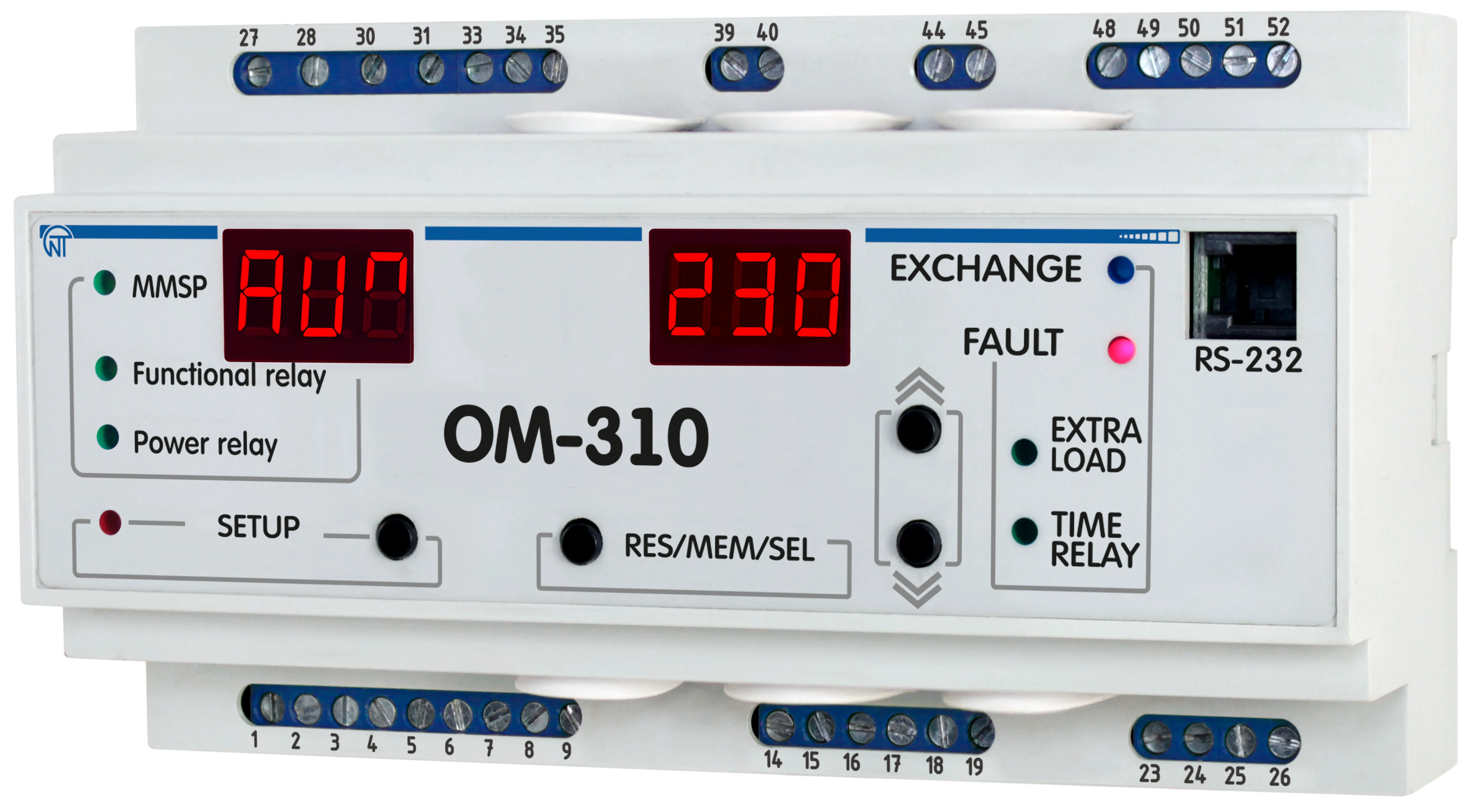
Front Panel Elements:
Figure 1.1 – OM-310 device controls and dimensions 1.2.5 Power Limiting FunctionsSection titled “1.2.5 Power Limiting Functions”1.2.5.1 Assumptions utilized in power limiter function description: a) Voltage and current protections are off or corresponding parameters values are within permissible limits b) When energized, the load relay will close after AR time ( c) Time specified by 1.2.5.2 Limitation of active power if parameter Under all relay activity conditions except using it for connection of additional loading: After OM-310 energizing, after AR time ( The main threshold value and the power overload calculation depend on the When
Where:
When
Simultaneously, the load input power is calculated for each phase separately and is compared with the second threshold (threshold calculation for each phase + 20%):
Watt consumption crossing the first and the second thresholds is considered crossing the main threshold. When
Figure 1.2 – OM-310 operation in the power limiting mode when Where:
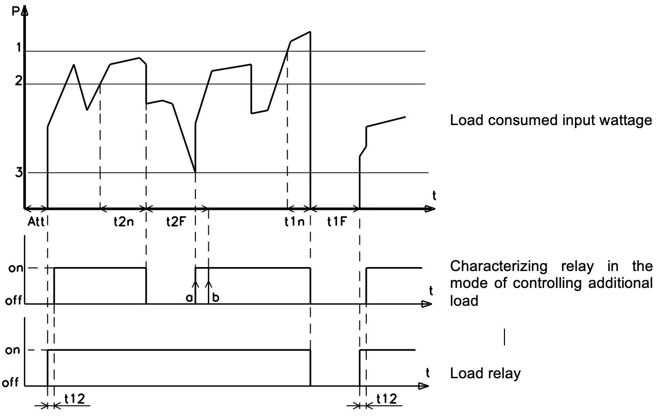
1.2.5.3 Active power limiting during operation of characterizing relay at When relay is used for connecting additional load: After OM-310 energizing, after AR time ( If during operation the active power consumed by the load crosses the additional threshold for a time period that is longer than assigned by Characterizing relay will re-close again: a) At b) At c) At If during operation the active power consumed by the load crosses the main threshold for a time period that is longer than assigned by The load relay and characterizing relay will be re-closed after AR period, or after time specified by
Figure 1.3 – OM-310 operation in the power limiting mode when Where:
The wattages values for the main threshold, the additional threshold, and the additional load energize threshold depend on the When
When When
At any value of
Where 1.2.6 Protection functionsSection titled “1.2.6 Protection functions”1.2.6.1 Protection types OM-310 device provides the following types of load protection:
1.2.6.2 The overcurrent protection parameters are assigned relatively to the rated load current In ( 1.2.6.3 Overcurrent protection The overcurrent protection is of three-phase type. It is engaged when at least one of the phase current values reach the tripping threshold. The protection has a time delay setting. The delay can be independent (constant), or dependent:
The tripping curves are displayed in Appendix A: Protection Curves.
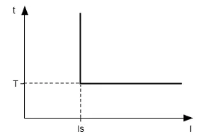
When independent time delay protection is activated, the load relay is de-energized if one of the phases current exceeds the threshold value within T period of time (parameter
Example: When Figure 1.4 – Principle of protection with an independent time delay
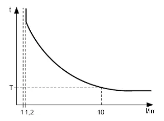
The operation of the dependent time delay protection conforms to IEC 60255-3 and BS 142 standards.
To deal with very high amperage currents the protection has a feature with an independent time delay. Figure 1.5 – Principle of protection with dependent time delay Graphs for the protection operation time constant equal to 1 sec ( When a different value for time constant is set, the protection trip time changes proportionally to the time constant (for example, at 1.2.6.4 Ground fault protection
1.2.6.5 Voltage based protection In voltage-based protections, before load energizing, OM-310 checks for corresponding threshold settings, and, depending on their value, either permits or prohibits load energization; after load energization the voltage control is retained. Voltage-based protections include:
1.2.6.6 Phase sequence protection trips in case of phase sequence order fault or phase coincidence – it opens the load relay and locks its further operation. 1.2.6.7 Starter unit operability control (at 1.3 Operating conditionsSection titled “1.3 Operating conditions”The product is designed for operation in the following conditions:
1.4 Product package contentsSection titled “1.4 Product package contents”Table 1.7 – Product package contents
* Supplied optionally 1.5 Equipment features and operationSection titled “1.5 Equipment features and operation”OM-310 is a microprocessor-based digital device that provides a high degree of reliability and accuracy. The device doesn’t need any auxiliary supply: it’s self-powered by the voltage to be monitored. OM-310 device is equipped with three built-in CTs, through which power phase mains are conducted. 2. Intended UseSection titled “2. Intended Use”2.1 SafetySection titled “2.1 Safety”2.2 OM-310 device controlSection titled “2.2 OM-310 device control”2.2.1 Control ModesSection titled “2.2.1 Control Modes”OM-310 has five control modes:
In all operation modes the following features are available:
2.2.2 Disabled keypad modeSection titled “2.2.2 Disabled keypad mode”When keypad is locked, viewing and resetting programmable parameters is not possible. When keypad is locked, pushing SETUP button will result in
If the password is correct, the keypad will be unlocked. If after the keypad was unlocked no button is pressed during 15 sec and the lockage setting is not released by user, the keypad will relock. The unblocked keypad allows:
2.2.3 MMSP – mode with minimum number of setting parametersSection titled “2.2.3 MMSP – mode with minimum number of setting parameters”MMSP is devised to ease the service personnel’s operations with OM-310. To employ MMSP mode in OM-310, the user needs to set In MMSP for normal activity of OM-310 it is enough to fix parameter On duty of external CT it is necessary to fix following parameters:
The difference between MMSP mode and the user mode is that the parameters not included in the MMSP register are set to default factory values. The parameters included in this register cannot be viewed or modified. Operations with the MMSP register parameters are similar to the user level operations. Adding parameters to the MMSP register and MMSP mode disabling is possible only in service engineer access mode. When switching off the MMSP mode (setting parameter 2.2.4 User levelSection titled “2.2.4 User level”To view and to change the user level parameters:
If no button is pressed during 30 sec the OM-310 will transfer to the initial state. If a parameter change is forbidden (a dot in the middle digit field of the parameter mnemonic indicator glows), then the parameter change is possible only in Service Engineer level after the prohibition has been released. 2.2.5 Service Engineer LevelSection titled “2.2.5 Service Engineer Level”Access to the Service Engineer level:
If the password is incorrect, the Scroll parameters with DOWN and UP buttons, enter parameter change mode – press SETUP button (the parameter value starts to flicker), change parameters – with DOWN and UP buttons, record parameter – RES/MEM/SEL, to return to menu without change – press SETUP button again. If no button is pressed during 30 sec the OM-310 will transfer to the initial state. While OM-310 is in Service Engineer mode, the decimal point in the lower digit position of the mnemonic indicator is on. In the Service Engineer level the access to any user level parameter can be prohibited or permitted by simultaneous pressing the SET and DOWN buttons. Access denial is indicated by decimal point in the middle digit position of the mnemonic indicator. Adding parameters to MMSP register (while in Service Engineer access mode):
Excluding a parameter from the MMSP register:
When a parameter is excluded from the MMSP mode register, a decimal point glows in the higher digit position of the mnemonic indicator. 2.2.6 Restoring factory settingsSection titled “2.2.6 Restoring factory settings”There are two ways to restore the factory settings. Way 1: Set up parameter Way 2: When powering OM-310 on, hold down SETUP and RES/MEM/SEL buttons for 2 seconds. All factory settings including the Service Engineer password will be restored (Service Engineer password – 123). After completion of the factory settings setup, OM-310 will start operation in MMSP mode, which includes the following parameters:
2.3 OM-310 pre-operation procedureSection titled “2.3 OM-310 pre-operation procedure”To improve the performance, it is recommended to install fuses (fuse links or their analogs) in the following circuits:
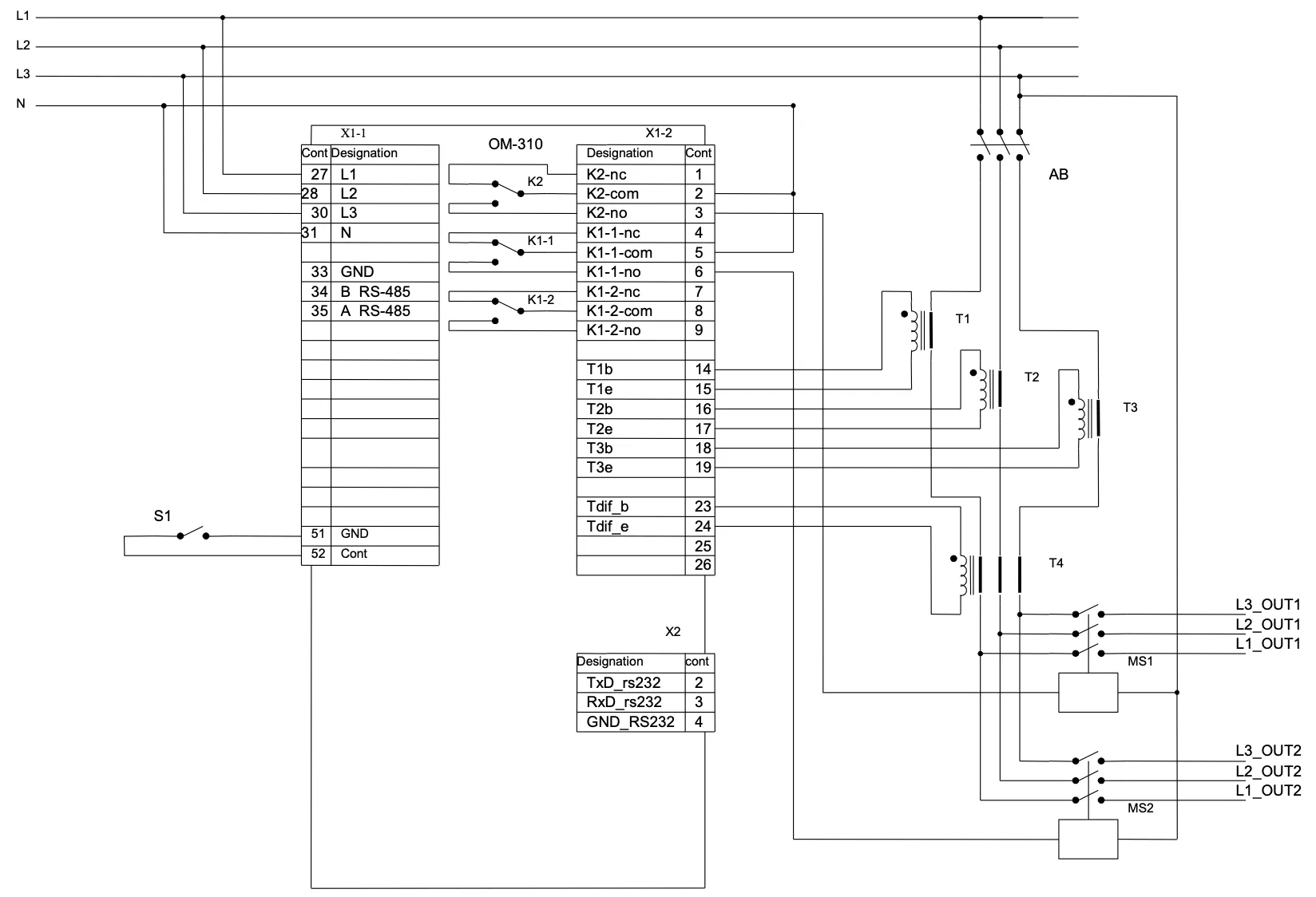
2.3.1 When operating with load power ranging from 3 kW to 30 kW, use of built-in current transformers is allowed. The mains leading to the load must be conducted through openings in OM-310 casing (each phase wire uses a separate opening). When using other capacity loads, current transformers with 5A rated output current shall be connected. For correct OM-310 operation, the current transformers’ polarity must be observed.
Figure 2.1 – OM-310 connection schematic with use of external CTs and at Where:
2.3.2 Run all three power phase cables through differential current transformer (zero sequence transformer) and connect the DCT to OM-310. 2.3.3 Connect OM-310 to power mains in accordance with Figure 2.1. 2.3.4 To operate OM-310 via PC as control or monitoring device with use of “OM-310 Control Panel” software:
2.3.5 When using MODBUS, connect communication lines to terminals 33, 34, 35 of OM-310. Set 2.3.6 Energize OM-310. Load relay closing sequence is controlled by 2.3.7 Set up required parameter values in the menu. 2.3.8 De-energize OM-310. 2.3.9 Connect the load magnetic contactor (MC) according to Figure 2.1. 2.4 Intended UseSection titled “2.4 Intended Use”2.4.1 OM-310 operation before load relay closureSection titled “2.4.1 OM-310 operation before load relay closure”2.4.1.1 OM-310 operation after power-on (first start) After power-on, the mnemonic indicator displays
When any of inhibiting factors is present, the load relay is not closed, and on the mnemonics indicator FAULT LED glows. Depending on the
When power-on inhibiting factors are not present, the load relay closure is defined by
Simultaneously with the load relay closure, green LED LOAD starts to glow. OM-310 operation with remote control permitted via RS-232/RS-485 ( OM-310 operation with remote control permitted via switch ( 2.4.1.2 OM-310 operation after a fault-caused de-energizing The OM-310 device operation in such case is similar to the first start operation, but the load relay closure is not dependent on the If after a fault AR is prohibited ( 2.4.1.3 OM-310 operation after de-energizing tripping caused by exceeding the watt input OM-310 operation in this case is covered under section 1.2.5. 2.4.2 OM-310 operation after load relay closureSection titled “2.4.2 OM-310 operation after load relay closure”After load relay closure OM-310 performs the following:
The indicator can display either phase A current or a user-selected parameter value. The value of the user-selected parameter can be displayed either constantly ( 2.4.3 Characterizing relay operationSection titled “2.4.3 Characterizing relay operation”Functions performed by the characterizing relay are defined by When When When When When 2.4.4 Work with RS-232/RS-485 interface under MODBUS protocol in RTU modeSection titled “2.4.4 Work with RS-232/RS-485 interface under MODBUS protocol in RTU mode”The OM-310 allows for data exchange with an external device via serial interface under MODBUS protocol. During data exchange via RS-485 or RS-232 blue LED “EXCHANGE” glows. 2.4.4.1 Communication parameters:
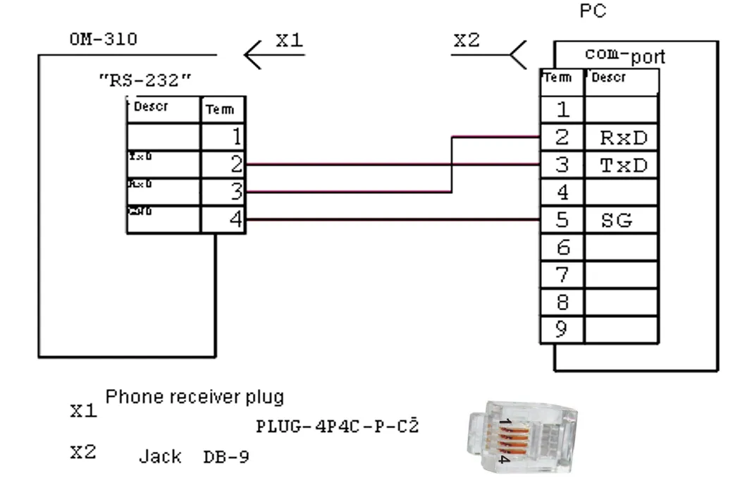
2.4.4.2 OM-310 control from PC Communication between PC and OM-310 is effected through serial interface. Each OM-310 has a unique communication address. PC controls each OM recognizing them by their address. OM-310 can operate within RTU mode controlled Modbus networks.
Figure 2.2 – OM-310 connection to PC schematic 2.4.4.3 Communication protocol The exchange between PC and OM-310 uses Modbus protocol. The data formats and parameters addresses are given in Appendix B: Modbus Communication. 2.4.4.8 Energy meters resetSection titled “2.4.4.8 Energy meters reset”Reset of energy meters (total, at all phases) is performed when setting the parameter “1” to register 239, when using RS-232/RS-485 interface. After reset of energy meters, OM-310 will automatically switch register 239 to parameter “0”. 2.4.5 Load energize/de-energize remote control via RS-232/RS-485 interfaceSection titled “2.4.5 Load energize/de-energize remote control via RS-232/RS-485 interface”OM-310 operation in the remote control mode is defined by the When When When The R_COMMAND register address and allowed values are given in Appendix B: Modbus Communication. 2.4.6 Load energize/de-energize via remote breakerSection titled “2.4.6 Load energize/de-energize via remote breaker”OM-310 operation in the remote control mode is defined by the When When When When 2.4.7 Fault conditions systemSection titled “2.4.7 Fault conditions system”In case of fault condition occurrence, the OM-310 performs following actions:
If OM-310 defines several types of faults simultaneously, the error codes and parameter values are displayed consecutively, one after one. If AR is permitted, the fault codes and time left till AR are displayed. Fault codes mnemonics, register flags and values are shown in Table 2.8 of Appendix B: Modbus Communication. 2.4.8 Fault conditions logSection titled “2.4.8 Fault conditions log”When load relay in case of fault opens, the OM-310 device stores the fault code, the parameter value, and time of occurrence. Number of synchronously stored fault codes is five. When next following faults occur, the information of this fault is recorded over the latest fault. To view log press RES/MEM/SEL button. The SETUP LED will start to flicker, and the OM-310 indicator panels will display line 1 from Table 2.9. Log scrolling performed by pressing UP and DOWN buttons. To exit log view mode press RES/MEM/SEL button, or the log will close automatically after 30 sec since last button was pressed. Table 2.9 – Fault log display
Fault log registers are shown in Appendix B: Modbus Communication. 2.4.9 Load start/cutoff control with use of OM-310 front panelSection titled “2.4.9 Load start/cutoff control with use of OM-310 front panel”Depending on the
3. MaintenanceSection titled “3. Maintenance”3.1 SafetySection titled “3.1 Safety”3.2 Maintenance scheduleSection titled “3.2 Maintenance schedule”Recommended maintenance schedule – semiannually. Maintenance scheduled operations consist of visual observation, during which wiring connection to OM-310 terminals is checked, casing integrity check for cracking and chipping. 4. Transportation and StorageSection titled “4. Transportation and Storage”OM-310 in manufacturer package should be stored in enclosed rooms at −45° to +60°C and exposed to no more than 80% of relative humidity when there are no fumes in the air that have a damaging effect on package and the equipment material. The customer shall provide for the OM-310 equipment protection against mechanical damage while in transport. 5. Period of Service, Storage, and Manufacturer’s WarrantySection titled “5. Period of Service, Storage, and Manufacturer’s Warranty”The unit service life is 10 years. Upon expiration of the service life you should contact the Manufacturer. Shelf life is 3 years. Warranty period of the unit operation is 5 years from the date of sale. During the warranty period the Manufacturer is responsible for free repair of the unit, if the Consumer has complied with the requirements of this Operating Manual. Warranty service is performed at the place of purchase or by the Manufacturer of the product. Post-warranty service is performed by the Manufacturer at current rates. Before sending for repair, the unit should be packed in the original or other packaging excluding mechanical damage. Contact Information: NOVATEK-ELECTRO Ltd. 59, Mykhailo Boltenko (Admiral Lazarev) str., Tel: +38 (067) 565 37 68 |
| | ||||||||||||||||||
|---|---|---|---|---|---|---|---|---|---|---|---|---|---|---|---|---|---|---|
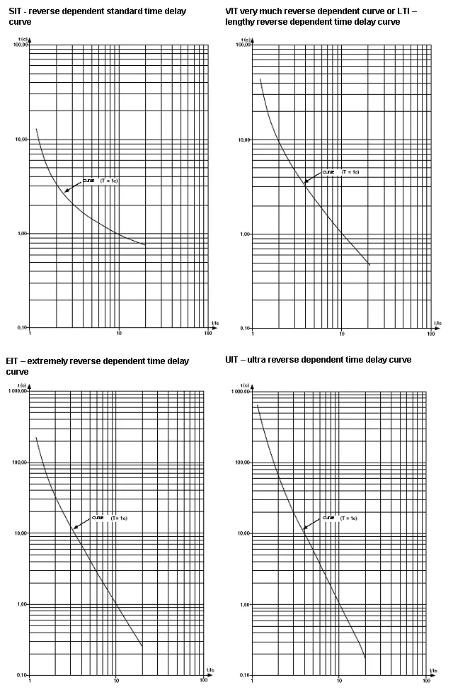
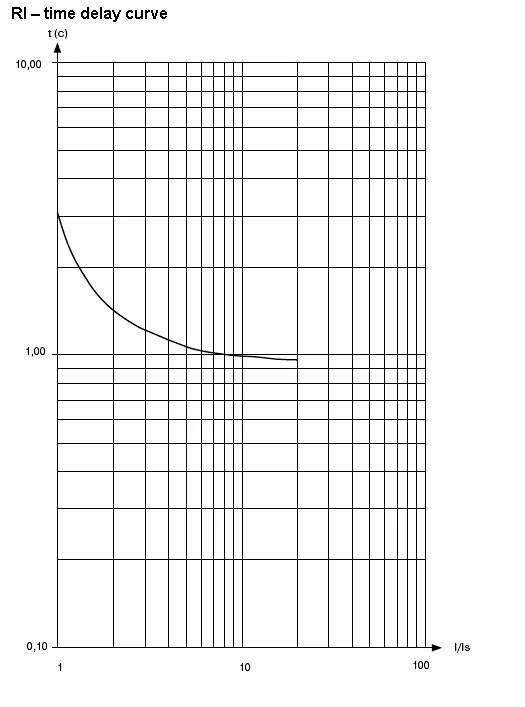
Appendix A: Protection CurvesDependent Time Delay Current Protection TypesSection titled “Dependent Time Delay Current Protection Types”The following curves show the relationship between current ratio (I/In) and trip time for different protection curve types when the time constant parameter it = 1 second. When a different value for time constant is set, the protection trip time changes proportionally to the time constant. For example, at it = 10 seconds, the protection trip time at the same current ratio will increase 10 times. Protection Curve TypesSection titled “Protection Curve Types”
Protection CurvesSection titled “Protection Curves”
Curve FormulasSection titled “Curve Formulas”The operation of the dependent time delay protection conforms to IEC 60255-3 and BS 142 standards. Standard Inverse Time (SIT): Very Inverse Time (VIT/LTI): Extremely Inverse Time (EIT): Ultra Inverse Time (UIT): Where:
Usage NotesSection titled “Usage Notes”
|
| | |||||||||||||||||||||||||||||||||||||||||||||||||||||||||||||||||||||||||||||||||||||||||||||||||||||||||||||||||||||||||||||||||||||||||||||||||||||||||||||||||||||||||||||||||||||||||||||||||||||||||||||||||||||||||||||||||||||||||||||||||||||||||||||||||||||||||||||||||||||||||||||||||||||||||||||||||||||||||||||||||||||||||||||||||||||||||||||||||||||||||||||||||||||||||||||||||||||||||||||||||||||||||||||||||||||||||||||||||||||||||||||||||||||||||||||||||||||||||||||||||||||||||||||||||||||||||||||||||||||||||||||||||||||||||||||||||||||||||||||||||||||||||||||||||||||||||||||||||||||||||||||||||||||||||||||||||||||||||||||||||||||||||||||||||||||||||||||||||||||||||||||||||||||||||||||||||||||||||||||||||||||||||||||||||||||||||||||||||||||||||||||||||||||||||||||||||||||||||||||||||||||||||||||||||||||||||||||||||||||||||||||||||||||||||||||||||||||||||||||||||||||||||||||||||||||||||||||||||||||||||||||||||||||||||||||||||||||||||||||||||||||||||||||||||||||||
|---|---|---|---|---|---|---|---|---|---|---|---|---|---|---|---|---|---|---|---|---|---|---|---|---|---|---|---|---|---|---|---|---|---|---|---|---|---|---|---|---|---|---|---|---|---|---|---|---|---|---|---|---|---|---|---|---|---|---|---|---|---|---|---|---|---|---|---|---|---|---|---|---|---|---|---|---|---|---|---|---|---|---|---|---|---|---|---|---|---|---|---|---|---|---|---|---|---|---|---|---|---|---|---|---|---|---|---|---|---|---|---|---|---|---|---|---|---|---|---|---|---|---|---|---|---|---|---|---|---|---|---|---|---|---|---|---|---|---|---|---|---|---|---|---|---|---|---|---|---|---|---|---|---|---|---|---|---|---|---|---|---|---|---|---|---|---|---|---|---|---|---|---|---|---|---|---|---|---|---|---|---|---|---|---|---|---|---|---|---|---|---|---|---|---|---|---|---|---|---|---|---|---|---|---|---|---|---|---|---|---|---|---|---|---|---|---|---|---|---|---|---|---|---|---|---|---|---|---|---|---|---|---|---|---|---|---|---|---|---|---|---|---|---|---|---|---|---|---|---|---|---|---|---|---|---|---|---|---|---|---|---|---|---|---|---|---|---|---|---|---|---|---|---|---|---|---|---|---|---|---|---|---|---|---|---|---|---|---|---|---|---|---|---|---|---|---|---|---|---|---|---|---|---|---|---|---|---|---|---|---|---|---|---|---|---|---|---|---|---|---|---|---|---|---|---|---|---|---|---|---|---|---|---|---|---|---|---|---|---|---|---|---|---|---|---|---|---|---|---|---|---|---|---|---|---|---|---|---|---|---|---|---|---|---|---|---|---|---|---|---|---|---|---|---|---|---|---|---|---|---|---|---|---|---|---|---|---|---|---|---|---|---|---|---|---|---|---|---|---|---|---|---|---|---|---|---|---|---|---|---|---|---|---|---|---|---|---|---|---|---|---|---|---|---|---|---|---|---|---|---|---|---|---|---|---|---|---|---|---|---|---|---|---|---|---|---|---|---|---|---|---|---|---|---|---|---|---|---|---|---|---|---|---|---|---|---|---|---|---|---|---|---|---|---|---|---|---|---|---|---|---|---|---|---|---|---|---|---|---|---|---|---|---|---|---|---|---|---|---|---|---|---|---|---|---|---|---|---|---|---|---|---|---|---|---|---|---|---|---|---|---|---|---|---|---|---|---|---|---|---|---|---|---|---|---|---|---|---|---|---|---|---|---|---|---|---|---|---|---|---|---|---|---|---|---|---|---|---|---|---|---|---|---|---|---|---|---|---|---|---|---|---|---|---|---|---|---|---|---|---|---|---|---|---|---|---|---|---|---|---|---|---|---|---|---|---|---|---|---|---|---|---|---|---|---|---|---|---|---|---|---|---|---|---|---|---|---|---|---|---|---|---|---|---|---|---|---|---|---|---|---|---|---|---|---|---|---|---|---|---|---|---|---|---|---|---|---|---|---|---|---|---|---|---|---|---|---|---|---|---|---|---|---|---|---|---|---|---|---|---|---|---|---|---|---|---|---|---|---|---|---|---|---|---|---|---|---|---|---|---|---|---|---|---|---|---|---|---|---|---|---|---|---|---|---|---|---|---|---|---|---|---|---|---|---|---|---|---|---|---|---|---|---|---|---|---|---|---|---|---|---|---|---|---|---|---|---|---|---|---|---|---|---|---|---|---|---|---|---|---|---|---|---|---|---|---|---|---|---|---|---|---|---|---|---|---|---|---|---|---|---|---|---|---|---|---|---|---|---|---|---|---|---|---|---|---|---|---|---|---|---|---|---|---|---|---|---|---|---|---|---|---|---|---|---|---|---|---|---|---|---|---|---|---|---|---|---|---|---|---|---|---|---|---|---|---|---|---|---|---|---|---|---|---|---|---|---|---|---|---|---|---|---|---|---|---|---|---|---|---|---|---|---|---|---|---|---|---|---|---|---|---|---|---|---|---|---|---|---|---|---|---|---|---|---|---|---|---|---|---|---|---|---|---|---|---|---|---|---|---|---|---|---|---|---|---|---|---|---|---|---|---|---|---|---|---|---|---|---|---|---|---|---|---|---|---|---|---|---|---|---|---|---|---|---|---|---|---|---|---|---|---|---|---|---|---|---|---|---|---|---|---|---|---|---|---|---|---|---|---|---|---|---|---|---|---|---|---|---|---|---|---|---|---|---|---|---|---|---|---|---|---|---|---|---|---|---|---|---|---|---|---|---|
Appendix B: Modbus CommunicationCommunication protocolSection titled “Communication protocol”The exchange between PC and OM-310 is effected via data packages. Data packet format (Table 2.1)Section titled “Data packet format (Table 2.1)”
CMD (command code) and DATA (data symbols)Section titled “CMD (command code) and DATA (data symbols)”Data symbols format depends on command codes. Command code 0x03 – n-words readSection titled “Command code 0x03 – n-words read”Example: Read 2 continuous words from address 0x64 (100) in OM-310 with communication address 0x01.
Command code 0x06 – write (record) one wordSection titled “Command code 0x06 – write (record) one word”Data writing is possible only to the programmable parameter’s addresses (Table 1.5), except for the following parameters:
Parameter writing is performed independently from the installed Service Engineer protection (the entry made via communication line has a higher priority). When a new parameter value is written into a MMSP-protected cell, such parameter will automatically be excluded from this mode. Command code 0x08 – diagnosticsSection titled “Command code 0x08 – diagnostics”0x08 function provides a number of tests for checking communication system between PC and OM-310, and for OM-310 integrity control. The function uses the sub function field to specify the action performed (test). Sub function 0x00 – query data responseSection titled “Sub function 0x00 – query data response”Data transferred in the query field must return in the response data field. Example: sub function 0x00 request and response in OM-310 with communication address 0x01.
Sub function 0x01 – communication options restartSection titled “Sub function 0x01 – communication options restart”OM-310 peripheral port shall be initialized and restarted. Example: sub function 0x01 request (response is not returned) for OM-310 with communication address 0x01.
CRC – Cyclic redundancy check codeSection titled “CRC – Cyclic redundancy check code”The checksum (CRC16) is a cyclic redundancy check code based on 0xA001 polynomial. The transmitting device forms the checksum for all bytes of the message transmitted. The receiving device similarly forms the checksum for all bytes of the message received, and compares it to the checksum received from the transmission device. When received and transmitted checksums do not match, an error message is generated. The checksum field size occupies two bytes. The checksum within message is transferred with low byte coming first. The checksum is registered under the following algorithm:
CRC code generation example in C: Communication error handlingSection titled “Communication error handling”When an error situation occurs at time of a frame receipt (parity error, frame error, checksum error), the OM-310 device does not return a response. When an error occurs in the format or in the value of the data transferred (unsupported function code, etc.), OM-310 receives the request frame and forms a response with the error indicator and code. A high-order function field bit inserted in the unit serves as error indicator. Example: function 0x30 error response (illegal function) from OM-310 with communication address 0x01.
Table 2.6 – Error codes
Measured and Displayed Parameters (Table 1.4)Section titled “Measured and Displayed Parameters (Table 1.4)”CurrentsSection titled “Currents”
VoltagesSection titled “Voltages”
Power and CosinesSection titled “Power and Cosines”
Timers and FrequencySection titled “Timers and Frequency”
Energy MetersSection titled “Energy Meters”
Programmable Parameters (Table 1.5)Section titled “Programmable Parameters (Table 1.5)”TransformersSection titled “Transformers”
Power ControlSection titled “Power Control”
Current Protection - Maximum CurrentSection titled “Current Protection - Maximum Current”
Current Protection - Ground Fault (iF0)Section titled “Current Protection - Ground Fault (iF0)”
Voltage ProtectionSection titled “Voltage Protection”
Load Engagement and Automatic ResetSection titled “Load Engagement and Automatic Reset”
MiscellaneousSection titled “Miscellaneous”
Serial Interface Parameters (RS-485/RS-232)Section titled “Serial Interface Parameters (RS-485/RS-232)”
Status and Fault RegistersSection titled “Status and Fault Registers”OM Status Register (Address 240)Section titled “OM Status Register (Address 240)”
Fault RegistersSection titled “Fault Registers”
Fault codes (Table 2.8)Section titled “Fault codes (Table 2.8)”
Fault Log RegistersSection titled “Fault Log Registers”
Fault Parameter Value RegistersSection titled “Fault Parameter Value Registers”
Command RegisterSection titled “Command Register”
The R_COMMAND value is regarded by the OM-310 operation algorithm when If If In case of an emergency load shutdown by simultaneous pressing DOWN+UP buttons (while Energy Meter ResetSection titled “Energy Meter Reset”
|