Novatek-Electro OB-216 Documentation
https://www.overvis.com/docs/en/ob-216/
2026-07-30
| |
|---|
Novatek-Electro OB-216
The OB-216 is a digital input/output module manufactured by NOVATEK-ELECTRO LTD. It provides versatile measurement and control capabilities via RS-485 and USB interfaces using the Modbus protocol, with analog output functionality. Key FeaturesSection titled “Key Features”
Common Use CasesSection titled “Common Use Cases”
DocumentationSection titled “Documentation”Getting StartedSection titled “Getting Started”
Advanced FeaturesSection titled “Advanced Features”
ResourcesSection titled “Resources”
SupportSection titled “Support”
|
| | ||||||||||||||||||||||||||||||||||||||||||||||||||||||||||||||||||||||||||||||||||||||||||||||||||||||||||||||||||||||||||||||||||||||||||
|---|---|---|---|---|---|---|---|---|---|---|---|---|---|---|---|---|---|---|---|---|---|---|---|---|---|---|---|---|---|---|---|---|---|---|---|---|---|---|---|---|---|---|---|---|---|---|---|---|---|---|---|---|---|---|---|---|---|---|---|---|---|---|---|---|---|---|---|---|---|---|---|---|---|---|---|---|---|---|---|---|---|---|---|---|---|---|---|---|---|---|---|---|---|---|---|---|---|---|---|---|---|---|---|---|---|---|---|---|---|---|---|---|---|---|---|---|---|---|---|---|---|---|---|---|---|---|---|---|---|---|---|---|---|---|---|---|---|---|
Quick Start and Application SetupThis guide takes the OB-216 from an unpowered installation to a verified Modbus reading. It also shows which input, operating mode, settings, and result register belong together for each supported application. Understand the device before wiringSection titled “Understand the device before wiring”
Choose the input applicationSection titled “Choose the input application”Use this table before connecting anything.
The wiring figures referenced above are reproduced in the relevant procedures below. The complete register definitions are in OB-216 settings and Additional Registers. Initial connection and configurationSection titled “Initial connection and configuration”What you needSection titled “What you need”
Application proceduresSection titled “Application procedures”0–10 V sensor (PLC / VFD output or other transmitter)Section titled “0–10 V sensor (PLC / VFD output or other transmitter)”Use this procedure for a sensor whose output voltage is within 0–10 V.
Example — 0.5–8 V pressure sensor representing 1–25 bar: set registers 131–134 to 0–20 mA sensor or transmitterSection titled “0–20 mA sensor or transmitter”
Example — 4.5–20 mA pressure sensor representing 1–25 bar: set registers 131–134 to NTC 10KB, PTC 1000, or PT 1000 analog temperature sensorSection titled “NTC 10KB, PTC 1000, or PT 1000 analog temperature sensor”
DS18B20 digital temperature sensorSection titled “DS18B20 digital temperature sensor”
DHT11, DHT21 / AM2301, or DHT22 sensorSection titled “DHT11, DHT21 / AM2301, or DHT22 sensor”
Dry-contact state inputSection titled “Dry-contact state input”
Pulse counterSection titled “Pulse counter”Choose the pulse mode that matches the signal source:
Analog outputSection titled “Analog output”The analog output can operate in one of two modes:
Automatic outputSection titled “Automatic output”
Manual outputSection titled “Manual output”
Connect the load to the current output (Figure 1, terminal 9) or voltage output (Figure 1, terminal 10), together with analog ground (terminal 8). Verification checklistSection titled “Verification checklist”Before considering setup complete, verify all of the following:
TroubleshootingSection titled “Troubleshooting”Q: Why is there no communication over USB? A: Confirm the 10–30 V supply is present, install the USB-SERIAL driver, and check that register 113 is not forced to RS-485 only. Q: Why is there no communication over RS-485? A: Disconnect USB, check Q: Why does the reading never change? A: Confirm that register 100 matches the wiring, verify that you are reading the correct result register, and check the sensor power and Q: Why does the digital sensor have no valid reading? A: Confirm that register 100 is set to Q: Why is the analog value incorrect by a factor of 10 or 100? A: Apply the register scaling shown in the relevant application procedure. Make sure you distinguish raw register 6 from converted register 16. Q: Why is the threshold status unexpected? A: For DHT sensors, check register 103. Also check the upper and lower values and their units in registers 104–105. Q: Why do new settings disappear after power loss? A: Write Q: Why is the pulse count too high or too low? A: Check edge selection (register 106), debounce (register 107), pulses per increment (register 108), the frequency limit, and the thresholds for voltage or current pulse modes. ReferenceSection titled “Reference”
|
| | ||||||||||||||||||||||||||||||||||||||||||||||||||||||||||||||||||||
|---|---|---|---|---|---|---|---|---|---|---|---|---|---|---|---|---|---|---|---|---|---|---|---|---|---|---|---|---|---|---|---|---|---|---|---|---|---|---|---|---|---|---|---|---|---|---|---|---|---|---|---|---|---|---|---|---|---|---|---|---|---|---|---|---|---|---|---|---|
OB-216 Operating Manual
NOVATEK-ELECTRO LTD Intelligent industrial electronic DIGITAL INPUT/OUTPUT MODULE OB-216 OPERATING MANUAL Quality control system on the development and production complies with requirements ISO 9001:2015 Dear customer, Company NOVATEK-ELECTRO LTD. thanks you for purchasing our devices. You will be able to use properly the device after carefully studying the Operating Manual. Keep the Operating Manual throughout the service life of the device. UKRAINE, Odesa — www.novatek-electro.com 1 PurposeSection titled “1 Purpose”Digital input/output module OB-216 (hereinafter referred to as the Device or OB-216) can be used as:
OB-216 provides:
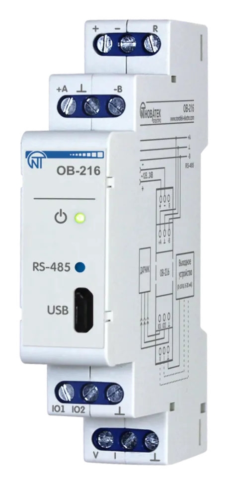
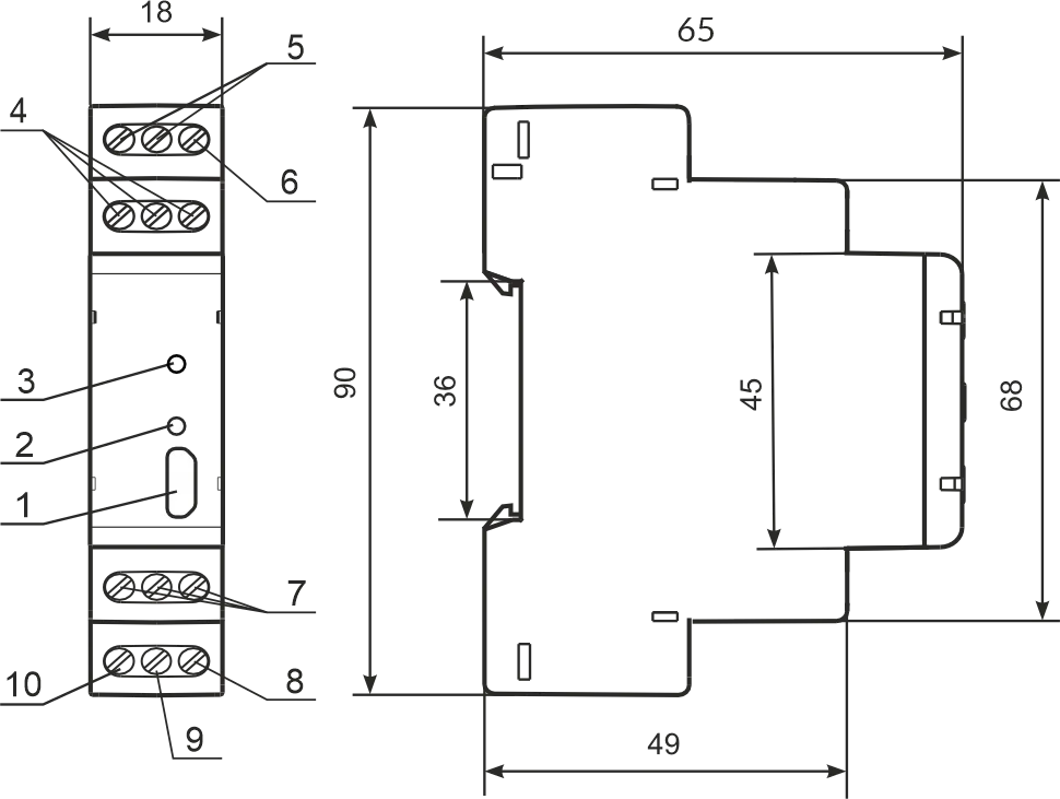
RS-485 or USB interfaces provide control over the Modbus protocol of devices connected to the analog output (Figure 1, pos. 9, 10), reading sensor readings, setting device parameters. The control is carried out using the program “Control Panel OB-215/OB-216” or other software supporting the MODBUS protocol. Power supply of the device and data exchange are indicated by indicators on the front panel (Figure 1, pos. 2, 3). The overall and mounting dimensions and controls of OB-216 are shown in Figure 1.
1 – microUSB connector; 2 – data exchange indicator; 3 – power supply indicator; 4 – terminals for RS-485 connection; 5 – terminals for power supply; 6 – terminal for restarting the device; 7 – terminals for connecting sensors; 8 – terminal “ground” of the analog output; 9 – current terminal 0 - 20 mA analog output; 10 – voltage terminal 0 - 10 V analog output. Figure 1 – OB-216 front panel and overall dimensions 2 Terms and AbbreviationsSection titled “2 Terms and Abbreviations”
3 Complete SetSection titled “3 Complete Set”
4 Technical SpecificationsSection titled “4 Technical Specifications”Main Technical CharacteristicsSection titled “Main Technical Characteristics”
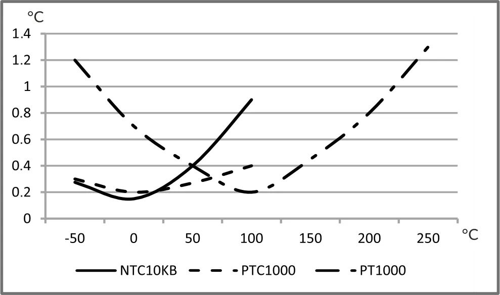
Temperature Measurement Error When Using Analog SensorsSection titled “Temperature Measurement Error When Using Analog Sensors”
5 Operation ConditionsSection titled “5 Operation Conditions”The device is intended for operation in the following conditions:
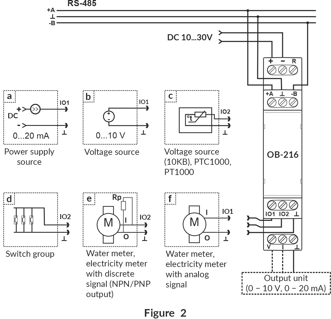
If the temperature of the device after transportation or storage differs from the ambient temperature at which it is supposed to be operated, then before connecting to the mains keep the device under the operating conditions within two hours (because of condensation may be on the product elements). 6 Connecting DeviceSection titled “6 Connecting Device”An error during installation work can damage the unit and appliances connected to it. For reliable contact, it is necessary to tighten the terminal block screws with force of 0.4 N·m. When the tightening torque is reduced, the junction may heat up, the terminal block may melt and the wire may catch fire. With an increase in the tightening torque, it is possible that the threads of the terminal block screws are broken or the wire to be connected is pinched. Analog Measurement Mode Wiring DiagramSection titled “Analog Measurement Mode Wiring Diagram”
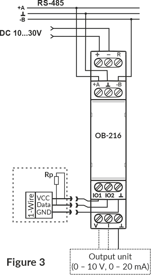
Figure 2 – Analog measurement mode wiring diagram Wiring Diagram for Operation with Digital SensorsSection titled “Wiring Diagram for Operation with Digital Sensors”
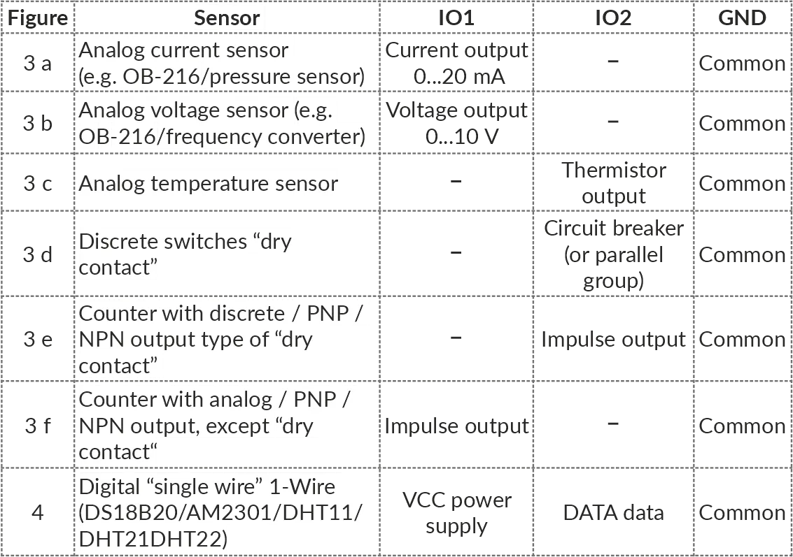
Figure 3 – Wiring diagram for operation with digital sensors 1. Connect the device in accordance with Figure 2 (when using the device in the mode of measuring analog and discrete signals) or in accordance with Figure 3 (when using the device with digital sensors) and check the correct connection. To connect the device to the Modbus network, use a twisted pair cable of Cat.1 category or higher. 2. Check the correct connection according to Connecting Different Types of Sensors and the diagrams in Figure 2 or Figure 3. Connecting Different Types of SensorsSection titled “Connecting Different Types of Sensors”
7 Use of DeviceSection titled “7 Use of Device”After power is applied, the indicator « ⏻ » flashes for 1.5 s, then the indicators « ⏻ » and «RS-485» (Figure 1, pos. 2, 3). After 0.5 s, the «RS-485» indicator goes out. During data exchange, the «RS-485» flashes, otherwise the indicator does not light up. To configure the device, use the program «Control Panel OB-215/OB-216» (available at website www.novatek-electro.com in the «Software» section) or other software compatible with the Modbus RTU/ASCII. The program connects to the device via USB or RS-485 interface. 8 Device OperationSection titled “8 Device Operation”Pulse Counter (Discrete Signal)Section titled “Pulse Counter (Discrete Signal)”Connect an external device according to Figure 2 (e).
Configure the device for operation in the pulse counter mode for counting discrete signals (OB-216 Settings, address 100, value 0).
Select the pulse detection algorithm in the In this mode, the device counts the number of pulses at the «IO2» (input with a duration not less than the value specified in the OB-216 Settings, address 107, the value is specified in ms). The data is saved into memory with a frequency of 1 minute. If the device was switched off before 1 minute has elapsed, the last stored value will be restored when switched on. Upon reaching the value indicated in the register (address 108), the counter is incremented by one (Additional Registers, address 4:5). To configure the initial value of the pulse counter, write the required value into the register (Additional Registers, address 4:5). Then the counter will count pulses from the entered value. When changing the value in the register (address 108), all stored pulse counter values will be deleted. Impulse Counter (By Voltage)Section titled “Impulse Counter (By Voltage)”Connect an external device according to Figure 2 (f).
Configure OB-216 to operate in the pulse counter mode for counting voltage pulses (OB-216 Settings, address 100, value 11). Select the pulse detection algorithm in the In this mode, the device counts the number of voltage pulses in accordance with the set thresholds. If the voltage value changes within the upper and lower thresholds, the device will not register these pulses. The number of impulses is saved to memory every minute. If the device was switched off before 1 minute has elapsed, the last stored value will be restored when switched on. Upon reaching the value indicated in the register (address 108), the counter is incremented by one (Additional Registers, address 4:5). To configure the initial value of the pulse counter, write the required value into the register (Additional Registers, address 4:5). Then the counter will add pulses to the initial value. When changing the value in the register (address 108), all stored pulse counter values will be deleted. Impulse Counter (By Current)Section titled “Impulse Counter (By Current)”Connect an external device according to Figure 2 (f).
Configure OB-216 to operate in the impulse counter mode for counting current impulses (OB-216 Settings, address 100, value 12).
Select the pulse detection algorithm in the In this mode, the device counts the number of current impulses in accordance with the set thresholds. If the current value changes within the upper and lower thresholds, the device will not register these impulses. The number of impulses is saved to memory every minute. If the device was switched off before 1 minute has elapsed, the last stored value will be restored when switched on. Upon reaching the value indicated in the register (address 108), the counter is incremented by one (Additional Registers, address 4:5). To configure the initial value of the impulse counter, write the required value into the register (Additional Registers, address 4:5). Then the counter will add pulses to the initial value. When changing the value in the register (address 108), all stored impulse counter values will be deleted. Logic InputSection titled “Logic Input”Connect the device according to Figure 2 (d). Configure it for operation in the «Logic input» (OB-216 Settings, address 100, value 1). When the logical state at the «IO2» terminal (Figure 1, pos. 7) changes to a low level, the device will set bit 18 (Additional Registers, address 2:3) equal to 1. When the logical state at the «IO2» terminal (Figure 1, pos. 7) changes to a high level, the device will reset bit 18 (Additional Registers, address 2:3) equal to 0. Voltage MeasurementSection titled “Voltage Measurement”Connect the device according to Figure 2 (b).
Configure it to operate in the «Voltage measurement» (OB-216 Settings, address 100, value 2).
The If the device has to indicate overvoltage (or undervoltage), the corresponding thresholds should be set (OB-216 Settings, addresses 104, 105). Write the upper threshold value to register 104 and lower threshold value to register 105. When the voltage value exceeds the threshold, the corresponding bit will be set to «1» (bit 20 – voltage value above the upper threshold, bit 21 – voltage value below the lower threshold) (see Additional Registers, address 2:3). Voltage Measurement with Value ConversionSection titled “Voltage Measurement with Value Conversion”To convert the measured voltage to another value, turn on the conversion (OB-216 Settings, address 130, value 1) and set the conversion ranges (addresses 131 – 134). For example, the measured voltage needs to be converted to pressure bars with the following sensor parameters:
Configure the conversion ranges as follows:
The converted value will be output to a Voltage Measurement with Analog Voltage OutputSection titled “Voltage Measurement with Analog Voltage Output”To output the measured voltage to the analog voltage output, select the analog voltage output (OB-216 Settings, address 150, value 1). Check the load connection for the voltage output (Figure 1, pos. 10). Set the conversion ranges (OB-216 Settings, registers 153-156). For example, to convert a measured voltage in the 1 V to 10 V range to a voltage in range of 0 V to 5 V:
The converted analog value will be output to a Voltage Measurement with Analog Current OutputSection titled “Voltage Measurement with Analog Current Output”To output the measured voltage to the analog current output, select the analog current output (OB-216 Settings, address 150, value 2). Check the load connection for the current output (Figure 1, pos. 9). Set the conversion ranges (OB-216 Settings, registers 153-156). For example, to convert a measured voltage in the 1 V to 10 V range to a current (4 mA to 20 mA range):
The converted analog value will be output to a Output Voltage to Analog Output in Manual ModeSection titled “Output Voltage to Analog Output in Manual Mode”To output voltage to the analog output in manual mode, select the analog voltage output (OB-216 Settings, address 150, value 3). Check the load connection for the voltage output (Figure 1, pos. 10). Afterwards use the register for writing value in manual mode (address 151) to control the output. For example, when the value To convert a manually set value, turn on the conversion of the output value by writing the value «1» to the register (address 152), and the required ranges in the corresponding registers (addresses 153-156). Current MeasurementSection titled “Current Measurement”Connect the device according to Figure 2 (a).
Configure it to operate in the «Current measurement» (OB-216 Settings, address 100, value 3).
The If the device has to indicate overcurrent (or undercurrent), the corresponding thresholds should be set (OB-216 Settings, addresses 104, 105). Write the upper threshold value to register 104 and lower threshold value to register 105. When the current value is out of range, the corresponding bit will be set to «1» (bit 22 – current value above the upper threshold, bit 23 – current value below the lower threshold) (see Status Register, address 2:3). Current Measurement with Value ConversionSection titled “Current Measurement with Value Conversion”To convert the measured current to another value, turn on the conversion (OB-216 Settings, address 130, value 1) and set the conversion ranges (addresses 131 – 134). For example, the measured current needs to be converted to pressure bars with the following sensor parameters:
Configure the conversion ranges as follows:
The converted value will be output to a Current Measurement with Analog Voltage OutputSection titled “Current Measurement with Analog Voltage Output”To output the measured current to the analog voltage output, select the analog voltage output (OB-216 Settings, address 150, value 1). Check the load connection for the voltage output (Figure 1, pos. 10). Set the conversion ranges (OB-216 Settings, registers 153-156). For example, to convert a measured current in the 0 mA to 20 mA range to a voltage (0 V to 5 V range):
The converted analog value will be output to a Current Measurement with Output to Analog Current OutputSection titled “Current Measurement with Output to Analog Current Output”To output the measured current to the analog current output, select the analog current output (OB-216 Settings, address 150, value 2). Check the load connection for the current output (Figure 1, pos. 9). Set the conversion ranges (OB-216 Settings, registers 153-156). For example, to convert a measured current in the 0 mA to 10 mA range to a current in range of 4 mA to 20 mA:
The converted analog value will be output to a Current Output to Analog Output in Manual ModeSection titled “Current Output to Analog Output in Manual Mode”To output current to the analog output in manual mode, select the analog current output (OB-216 Settings, address 150, value 4). Check the load connection for the current output (Figure 1, pos. 9). Afterwards use the register for writitng value in manual mode (address 151) to control the output. For example, when the value To convert a manually set value, turn on the conversion of the output value by writing the value «1» to the register (address 152), and the required ranges in the corresponding registers (addresses 153-156). Temperature MeasurementSection titled “Temperature Measurement”In this mode, the device measures the temperature using an external analog thermistor. Connect the device according to Figure 2 (c).
Configure it for operation in the «Temperature measurement» (OB-216 Settings, address 100, value 4, 5 or 6).
The Temperature values are displayed with an accuracy of tenths of a degree Celsius (1234 = 123.4 °С; 123 = 12.3 °С). If the device has to indicate overheat (or underheat), the corresponding thresholds should be set (OB-216 Settings, addresses 104, 105). Write the upper threshold value to register 104 and lower threshold value to register 105. When the temperature value is out of range, the corresponding bit will be set to «1» (bit 24 – temperature above the upper threshold, bit 25 – temperature below the lower threshold) (see Status Register, address 2:3). In order to correct the temperature measured by the sensor, enter the correction temperature into register 102 (OB-216 Settings), in tenths of a degree Celsius. Temperature Measurement with Analogue OutputSection titled “Temperature Measurement with Analogue Output”To output the measured temperature to the analog output, write to the Connecting Digital SensorsSection titled “Connecting Digital Sensors”The device supports digital sensors (one at a time) specified in the OB-216 Settings (address 101). The measured values of the digital sensor can be read from the Temperature values are displayed with an accuracy of tenths of a degree Celsius ( In order to correct the temperature measured by a digital sensor, enter the correction temperature into register 102 (OB-216 Settings), in tenths of a degree Celsius. If the device has to indicate excess (or deficit) of the measured value, the working parameter and the corresponding thresholds should be set (OB-216 Settings, addresses 103, 104, and 105). Select the working parameter in the register 103. Write the upper threshold value to register 104 and lower threshold value to register 105. When the working parameter value exceeds the threshold, the corresponding bit will be set to «1» (bits 24 and 25 – temperature value above the upper or below the lower threshold, bits 26 and 27 – humidity value above the upper or below the lower threshold) (see Additional Registers, address 2:3). Connection of Digital Sensors with Output to Analog OutputSection titled “Connection of Digital Sensors with Output to Analog Output”To output the working parameter of the digital sensor (OB-216 Settings, address 103) to the analog output, write to the 9 Restarting the Device and Resetting to the Factory SettingsSection titled “9 Restarting the Device and Resetting to the Factory Settings”If you need to restart the device, close and hold contacts «R» and «–» for 3 seconds (Figure 1). If it is required to restore the factory settings of the device, close and hold contacts «R» and «–» for more than 10 seconds (Figure 1). After 10 seconds, the device will restore factory settings and reboot. Also, the above actions can be performed through the command register by writing the corresponding command into it (Command Registers, address 50). 10 Modbus Interface ReferenceSection titled “10 Modbus Interface Reference”For USB and RS-485 interface configuration, supported functions, registers, message formats, and command details, see the dedicated OB-216 Modbus Interface Reference. 11 Safety PrecautionsSection titled “11 Safety Precautions”It is not allowed water penetration on terminals and internal elements of the device. During operation and maintenance, the regulatory document requirements must be met, namely:
12 Maintenance ProcedureSection titled “12 Maintenance Procedure”Recommended frequency of maintenance is every six months. Maintenance Procedure:
Do not use abrasives and solvents for cleaning. 13 Transportation and StorageSection titled “13 Transportation and Storage”The device in the original package is permitted to be transported and stored at the temperature from minus 45 to +60 °C and relative humidity of no more than 80 %, not in aggressive environment. 14 Service Life and WarrantySection titled “14 Service Life and Warranty”The lifetime of the device is 10 years. Shelf life is 3 years. Warranty period of the device operation is 5 years from the date of sale. During the warranty period of operation, the manufacturer performs free repair of the device, if the user has complied with the requirements of the Operating Manual. Warranty service is performed at the place of purchase or by the manufacturer of the device. Post-warranty service of the device is performed by the manufacturer at current rates. Before sending for repair, the device should be packed in the original or other packing excluding mechanical damage. For all questions, please contact the manufacturer: “Novatek-Electro” Ltd. 59, Mykhailo Boltenko (Admiral Lazarev) str., Odesa, Ukraine, 65007 Tel: +38 (067) 565 37 68 +38 (050) 359 39 11 +38 (063) 301 30 40 VN250731 |
| | ||||||||||||||||||||||||||||||||||||||||||||||||||||||||||||||||||||||||||||||||||||||||||||||||||||||||||||||||||||||||||||||||||||||||||||||||||||||||||||||||||||||||||||||||||||||||||||||||||||||||||||||||||||||||||||||||||||||||||||||||||||||||||||||||||||||||||||||||||||||||||||||||||||||||||||||||||||||||||||||||||||||||||||||||||||||||||||||||||||||||||||||||||||||||||||||||||||||||||||||||||||||||||||||||||||||||||||||||||||||||||||||
|---|---|---|---|---|---|---|---|---|---|---|---|---|---|---|---|---|---|---|---|---|---|---|---|---|---|---|---|---|---|---|---|---|---|---|---|---|---|---|---|---|---|---|---|---|---|---|---|---|---|---|---|---|---|---|---|---|---|---|---|---|---|---|---|---|---|---|---|---|---|---|---|---|---|---|---|---|---|---|---|---|---|---|---|---|---|---|---|---|---|---|---|---|---|---|---|---|---|---|---|---|---|---|---|---|---|---|---|---|---|---|---|---|---|---|---|---|---|---|---|---|---|---|---|---|---|---|---|---|---|---|---|---|---|---|---|---|---|---|---|---|---|---|---|---|---|---|---|---|---|---|---|---|---|---|---|---|---|---|---|---|---|---|---|---|---|---|---|---|---|---|---|---|---|---|---|---|---|---|---|---|---|---|---|---|---|---|---|---|---|---|---|---|---|---|---|---|---|---|---|---|---|---|---|---|---|---|---|---|---|---|---|---|---|---|---|---|---|---|---|---|---|---|---|---|---|---|---|---|---|---|---|---|---|---|---|---|---|---|---|---|---|---|---|---|---|---|---|---|---|---|---|---|---|---|---|---|---|---|---|---|---|---|---|---|---|---|---|---|---|---|---|---|---|---|---|---|---|---|---|---|---|---|---|---|---|---|---|---|---|---|---|---|---|---|---|---|---|---|---|---|---|---|---|---|---|---|---|---|---|---|---|---|---|---|---|---|---|---|---|---|---|---|---|---|---|---|---|---|---|---|---|---|---|---|---|---|---|---|---|---|---|---|---|---|---|---|---|---|---|---|---|---|---|---|---|---|---|---|---|---|---|---|---|---|---|---|---|---|---|---|---|---|---|---|---|---|---|---|---|---|---|---|---|---|---|---|---|---|---|---|---|---|---|---|---|---|---|---|---|---|---|---|---|---|---|---|---|---|---|---|---|---|---|---|---|---|---|---|---|---|---|---|---|---|---|---|---|---|---|---|---|---|---|---|---|---|---|---|---|---|---|---|---|---|---|---|
OB-216 Modbus Interface Reference
OB-216 SettingsSection titled “OB-216 Settings”Table – OB-216 Settings Setting operating modes (Address 100)
Operating mode values:
Connected digital sensor (Address 101)
Connectable digital sensor values:
Temperature and threshold settings (Addresses 102–105)
Working parameter values:
Settings for the pulse counter (Addresses 106–108)
Pulse counter mode values:
Data transfer settings (Addresses 109–116)
RS-485 protocol values:
Exchange rate values:
Parity and stop bits control values:
Interface selection values:
Measured value conversion settings (Addresses 130–134)
Measured value conversion values:
Settings for analog output (Addresses 150–156)
Analog output control values:
Converting the manual control value to analog signal values:
Notes:
Command RegistersSection titled “Command Registers”
Notes:
Command codes
Additional RegistersSection titled “Additional Registers”
Notes:
Status Register (Address 2:3)Section titled “Status Register (Address 2:3)”
Status bits:
Configuring the Device for USB OperationSection titled “Configuring the Device for USB Operation”If the register (address 113) contains the value «0» (automatic selection of the interface), the device will automatically switch and work with USB, while OB-216 is connected to the PC via a USB cable (the RS-485 interface is unavailable while it does). Otherwise, if the cable is disconnected, the device works with the RS-485 interface. To work with the RS-485 interface only , it is necessary to write the value «1», to the register (address 113); with this setting, the device will not switch to work with USB when the cable is connected. To work with the USB interface only, it is necessary to write the value «2», to the register (address 113), with this setting the device will work only with the USB interface, and access to the device via RS-485 will be prohibited. Modbus protocol usageSection titled “Modbus protocol usage”OB-216 allows data exchange with external devices using the Modbus protocol with a limited set of commands (the list is given in List of Supported Functions). When building a network, the bus topology and master-slave organization is used, where OB-216 acts as a slave. Only one master can be present on the network with one or several slaves. A personal computer software or a programmable logic controller usually acts as a master node. With this organization, only the master node can act as the initiator of exchange cycles. Host requests are individual (addressed to a specific device). OB-216 transmits in response to individual requests from the master. If errors are detected in receiving requests, or if it is impossible to execute the received command, OB-216, as a response, generates an error message. The addresses (in decimal) of the settings registers and their purpose are shown in Settings Registers. The addresses (in decimal) of the command registers, commands and their purpose are shown in Command Registers. Addresses (in decimal) of additional registers and their purpose are given in Additional Registers. The address (in decimal) of the status register and its purpose is given in Status Register. List of Supported FunctionsSection titled “List of Supported Functions”
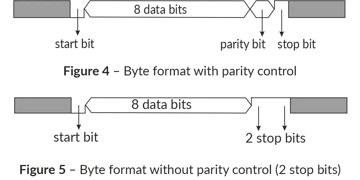
Message FormatsSection titled “Message Formats”The exchange protocol has clearly defined message formats. Compliance with the formats ensures the correctness and stability of the network. Byte FormatSection titled “Byte Format”OB-216 is configured to operate with one of two formats of data bytes: with parity control (Figure 4) and without parity control (Figure 5). In parity control mode, the type of control is also indicated: Even or Odd. Transmission of data bits is performed by the least significant bits forward. By default (during manufacture) the device is configured to operate without parity control and with two stop bits. Byte transfer is performed at speeds of 1200, 2400, 4800, 9600, 14400 and 19200 bps. By default, during manufacturing, the device is configured to operate at a speed of 9600 bps.
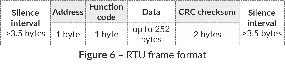
Figure 4, 5 – Byte format with parity control (top) and without parity control (bottom) Frame FormatSection titled “Frame Format”The frame length cannot exceed 256 bytes for Modbus RTU and 513 bytes for Modbus ASCII. In Modbus RTU mode the start and end of the frame are monitored by silence intervals of at least 3.5 bytes. The frame must be transmitted as a continuous byte stream. The correctness of frame acceptance is additionally controlled by checking the CRC checksum in the last two bytes. The RTU address field occupies one byte. The addresses of the slaves are in the range from 1 to 247. Figure 6 shows the RTU frame format.
Figure 6 – RTU frame format In Modbus ASCII mode the start and end of the frame are controlled by special characters:
The frame must be transmitted as a continuous stream of hexadecimal characters. As the frame is bounded by special characters, the timings of the transmissions are not as strict as those for RTU frame. The correctness of frame acceptance is additionally controlled by checking the LRC checksum in the last two transmitted hexadecimal characters. The address field occupies two hexadecimal characters. The addresses of the slaves are in the range from 1 to 247. Figure 7 shows the ASCII frame format.
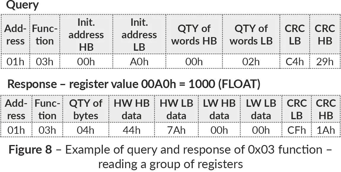
Figure 7 – ASCII frame format Checksum Generation and VerificationSection titled “Checksum Generation and Verification”The transmitting device generates a checksum for all bytes of the transmitted message. OB-216 similarly generates a checksum for all bytes of the received message and compares it with the checksum received from the transmitting device. If the generated and received checksums do not match, an error message is generated. CRC Checksum GenerationSection titled “CRC Checksum Generation”The checksum in the message is sent by the least significant byte forward. It is a cyclic redundant code verification based on the irreducible polynomial 0xA001. Subroutine for CRC checksum generation in C language: LRC Checksum GenerationSection titled “LRC Checksum Generation”The checksum in the message is transmitted by the most significant byte forward, which is a longitudinal redundancy check. Subroutine for LRC checksum generation in C language: Command SystemSection titled “Command System”Function 0x03 – Reading a Group of RegistersSection titled “Function 0x03 – Reading a Group of Registers”Function 0x03 provides reading of the contents of registers OB-216. The master query contains the address of the initial register, as well as the number of words to read. The OB-216 response contains the number of bytes to return and the requested data. The number of registers returned is limited to 50. If the number of registers in the query exceeds 50 (100 bytes), the response is not divided into frames. An example of the query and response in Modbus RTU is shown in Figure 8.
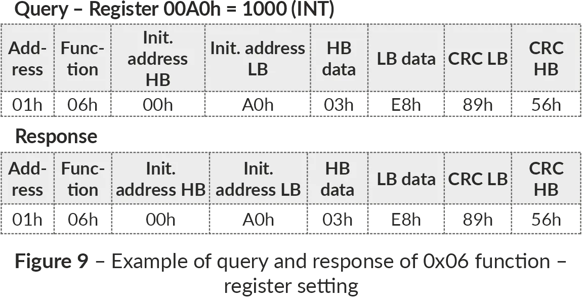
Figure 8 – Example of reading registers (Function 0x03) Function 0x06 – Recording the RegisterSection titled “Function 0x06 – Recording the Register”The function 0x06 provides recording in one OB-216 register. The master query contains the address of the register and the data to be written. The device response is the same as the master query and contains the register address and the set data. An example of the query and response in Modbus RTU mode is shown in Figure 9.
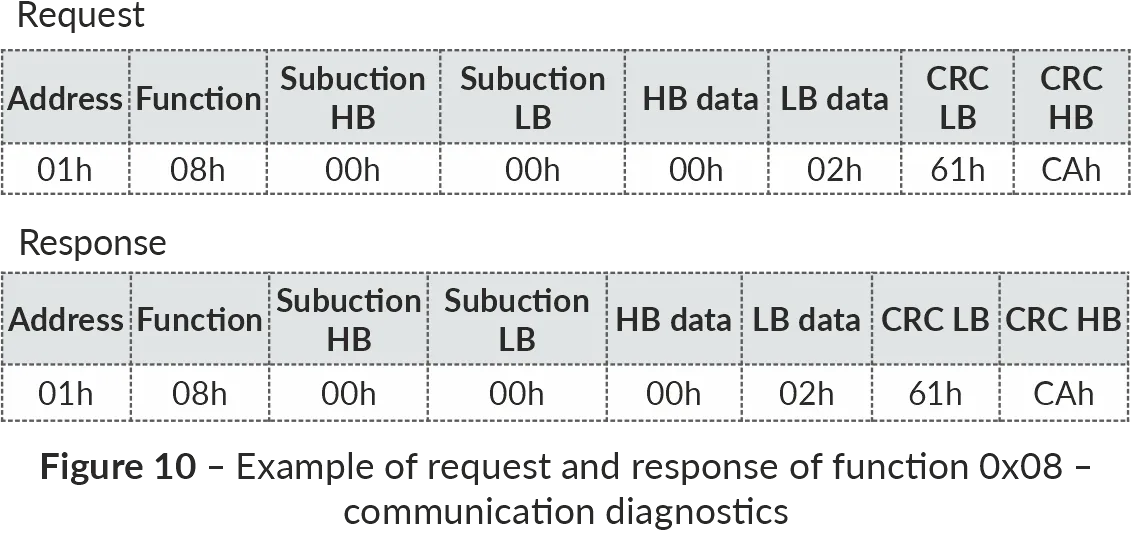
Figure 9 – Example of writing to a register (Function 0x06) Function 0x08 – Communication DiagnosticsSection titled “Function 0x08 – Communication Diagnostics”Subfunction 0x00 - returns the received data, the response is identical to the request. An example of a request and response is shown in Figure 10.
Figure 10 – Example of communication diagnostics (Function 0x08) Modbus Error CodesSection titled “Modbus Error Codes”
|
| |
|---|
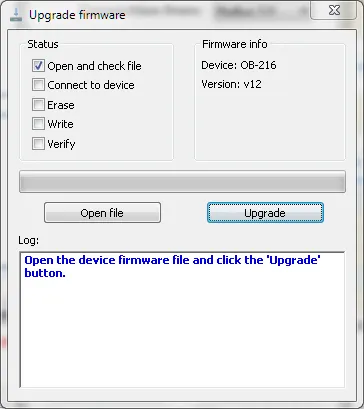
Firmware UpdateTo update the firmware, the Before you startSection titled “Before you start”Checking current versionSection titled “Checking current version”Before updating, check your current firmware version to see if an update is necessary. You can find the version number:
Getting the update file into OB-216Section titled “Getting the update file into OB-216”To write the update files into the OB-216 memory:
Troubleshooting & FAQSection titled “Troubleshooting & FAQ”Q: Will I lose my configuration or data during an update? A: No, the firmware update to a newer version process is designed to preserve your device configuration, and Modbus settings. However, downgrading the firmware may revert the settings to factory defaults. In either case, backing up critical data is always recommended. Q: The A: Disconnect the application from the device, then use Q: The Control Panel application does not recognize the file, and no file version is displayed. A: Check the following:
Q: The update process seems to hang. A: The update process typically takes 20-30 minutes. If it takes significantly longer:
Q: Can I downgrade the firmware? A: Yes, you can install an older firmware version by sending the older firmware file to the device. However, the device settings are not always retained and may be reverted to factory defaults after firmware downgrade. Need Help?Section titled “Need Help?”For technical support and assistance:
|
| | ||||||||
|---|---|---|---|---|---|---|---|---|
Firmware DownloadsLatest VersionSection titled “Latest Version”
See Firmware update instructions for the way to update the firmware. ChangelogSection titled “Changelog”Version 12Section titled “Version 12”2020-03-16 Download
Version 11Section titled “Version 11”2019-08-08
Version 10Section titled “Version 10”2019-04-15
|
| |
|---|
Additional SoftwareThis page lists the software available for configuring and monitoring the Overvis OB-216 Digital Input/Output Module. Control Panel OB-215/OB-216Section titled “Control Panel OB-215/OB-216”
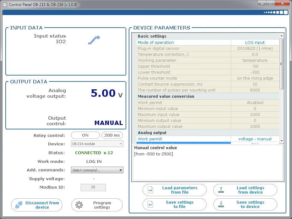
Control Panel OB-215/OB-216 is a Windows application for configuring the OB-215 and OB-216 through their Modbus communication interfaces. Use the application to:
For initial connection and configuration instructions, see Quick Start and Application Setup. Download: setup_cpl_ob21x(ver1.0.8).exe |