MC252 Documentation
https://www.overvis.com/docs/en/mc252/
2026-07-30
| |
|---|
Overvis MC252
The Overvis MC252 is a programmable RS-485 to Ethernet / GSM / LTE gateway and controller designed for industrial automation and remote monitoring applications. It bridges Modbus RTU/ASCII protocols to modern TCP/IP networks, enabling seamless integration of legacy industrial equipment with SCADA systems, cloud platforms, and IoT infrastructures. Key CapabilitiesSection titled “Key Capabilities”
Common Use CasesSection titled “Common Use Cases”
Documentation StructureSection titled “Documentation Structure”Getting StartedSection titled “Getting Started”
ConfigurationSection titled “Configuration”
Advanced FeaturesSection titled “Advanced Features”
ResourcesSection titled “Resources”
SupportSection titled “Support”
Ready to get started? Head to the Quick Start Guide to set up your MC252 in minutes. |
| |
|---|
Quick Start GuideThis guide walks you through setting up your Overvis MC252 gateway from wiring to successful connection in about 15 minutes. The Overvis MC252 is a programmable gateway that bridges RS-485 Modbus devices to modern networks, letting you monitor and control industrial equipment remotely via Ethernet or cellular connections. What You’ll NeedSection titled “What You’ll Need”From the delivery box: MC252 device, Ethernet cable, GSM antenna, 2GB microSD card. You’ll also need:
Step 1: Physical SetupSection titled “Step 1: Physical Setup”Mount your MC252 on a standard 35mm DIN rail in a well-ventilated location. The device operates from -35°C to +55°C, but avoid areas with excessive vibration, humidity, or corrosive atmospheres. Install memory card: Insert the provided 2GB microSD card into the Install SIM card (if using GSM/LTE): If you plan to use cellular connectivity, insert your SIM card (with data service enabled) into the Network connection: Connect the Ethernet cable from MC252’s Before making any electrical connections, ensure all devices are powered off. Tighten terminal screws to 0.4 N·m — enough for solid contact without damage. RS-485 wiring: Connect twisted-pair cable to MC252’s Power: Connect 12V DC power to the
Step 2: Power OnSection titled “Step 2: Power On”When you apply power, all LEDs light up briefly during the 2-second initialization, then the device spends 10-15 seconds establishing network connections. The The display shows IP addresses (prefixed with Step 3: Access Web Interface and ConfigureSection titled “Step 3: Access Web Interface and Configure”Note the IP address from the display (press Connecting directly to a PC?Without a DHCP server, the device uses default Open a web browser and enter the IP address shown on the display (e.g., Login to dashboard: You’ll see a login page. Press the Configure network (LAN/Internet tab): Enable/disable DHCP, set static IP if needed, adjust subnet mask and gateway. For GSM, enter your mobile operator’s APN (Access Point Name) and SIM card PIN (if present). Configure Modbus RTU/ASCII (Modbus tab): Consult the manual of your Modbus devices for their exact baud rate, parity and stopbits settings, then match these exactly in MC252. If no manual is available, start with common values: 9600 or 19200 baud, Modbus RTU protocol, and AUTO-STOP parity (which automatically detects the correct stopbits setting). MC252 has Modbus TCP server enabled by default on port 502. You can change the port or set Modbus passwords here if needed. For detailed information about all web interface options, see the Web Interface Guide. Step 4: Test Modbus TCP ConnectionSection titled “Step 4: Test Modbus TCP Connection”Use a Modbus client application to test the gateway. Connect to MC252’s IP address (from the display) on port 502.
Common issues:
Step 5: Connect to Overvis Cloud (Optional)Section titled “Step 5: Connect to Overvis Cloud (Optional)”Overvis Cloud provides remote monitoring and control through a web dashboard. The device label includes a QR code and PIN for quick setup.
Troubleshooting cloud connection:
TroubleshootingSection titled “Troubleshooting”Display shows Display shows Can’t access web interface: Verify IP address entered in browser matches what’s on the display. Ensure Ethernet address is used (the one marked with GSM won’t connect: Verify SIM card is fully inserted (until you hear a click), check the antenna is attached, check the GSM settings. Check that data service is active. Check signal strength on display (should be >0%). Try relocating antenna to better position. Try to disable PIN. Try manually configured APN settings. RS-485 devices don’t respond: Most common issue is mismatched settings. Verify baud rate matches all the devices. Check A/B wiring polarity (swapping these is very common - this doesn’t cause equipment damage, but prevents communication). Try increasing delays in MC252 settings for RS-485. Ensure protocol (Modbus RTU/ASCII) and parity are the same for all the devices. Start with 9600 baud, RTU, AUTO-STOP parity. Service Button Quick ReferenceSection titled “Service Button Quick Reference”The Quick press: Wake display, show status, grant temporary web access Hold 2-8 seconds: Prepare for safe memory card removal and restart device Hold 8+ seconds: Factory reset (erases all settings) What’s Next?Section titled “What’s Next?”
Need Help?Section titled “Need Help?”For technical support and assistance:
|
| | ||||||||||||||||||||||||||||||||||||||||||||||||||||||||||||||||||||||||||||||||||||
|---|---|---|---|---|---|---|---|---|---|---|---|---|---|---|---|---|---|---|---|---|---|---|---|---|---|---|---|---|---|---|---|---|---|---|---|---|---|---|---|---|---|---|---|---|---|---|---|---|---|---|---|---|---|---|---|---|---|---|---|---|---|---|---|---|---|---|---|---|---|---|---|---|---|---|---|---|---|---|---|---|---|---|---|---|
Overvis MC252 Modbus Gateway with 4G/Ethernet/RS-485 Operating Manual
This Operating Manual explains the design, safety requirements, operating rules, and maintenance procedures for the Overvis MC252 Modbus Gateway with 4G/Ethernet/RS-485. Safety informationSection titled “Safety information”During operation and maintenance, observe the requirements of applicable regulatory documents, including:
Only qualified personnel who have studied this Operating Manual should perform installation, adjustment, and maintenance. When used in accordance with this manual, the Overvis MC252 is safe in operation. The Overvis MC252 meets the requirements of the following standards: EN 60947-1; EN 60947-6-2; EN 55011; EN 61000-4-2. The device contains no hazardous substances in excess of maximum permissible limits. The development and production quality management system complies with ISO 9001:2015. General descriptionSection titled “General description”The Overvis MC252 is a programmable RS-485 to Ethernet / GSM / LTE gateway and controller. It:
The Overvis MC252 provides the following capabilities:
Front panel and indicatorsSection titled “Front panel and indicators”
Fig.1 – Overall and mounting dimensions of MC252
Fig.2 – Controls of the Overvis MC252
Operating conditionsSection titled “Operating conditions”The Overvis MC252 is designed for operation under the following environmental conditions:
Delivery setSection titled “Delivery set”Table 1 – MC252 delivery set
Technical specificationsSection titled “Technical specifications”Table 2 – MC252 technical specifications
* Establishing connections in Ethernet / GSM / Internet networks can take more time. Device architectureSection titled “Device architecture”MC252 provides control over Modbus devices in an RS-485 network via Ethernet interfaces, GSM / LTE, or SMS. It also supports reading Modbus data. The processor supports connection to a cloud server:
In addition, MC252 can be connected via the Modbus TCP protocol to exchange data with Modbus devices or with another MC252 controller. MC252 receives and processes SMS messages that contain a password and a read/write command for Modbus devices. When you insert a memory card, MC252 loads the operation logic program into internal memory. This program defines data collection and event tracking. It runs in the background. You can write collected data to the memory card in tabular or binary format. For registered events, you can configure actions such as sending SMS messages or writing corrected Modbus values. MC252 stores network settings, security parameters, and operation logic in its built-in memory. Installation and wiringSection titled “Installation and wiring”Before you start:
Wiring requirementsSection titled “Wiring requirements”If the temperature of MC252 after transportation or storage differs from the ambient operating temperature, keep MC252 under operating conditions for at least two hours before connecting it to the power supply. This prevents condensation on internal components. To ensure reliable electrical connections, use flexible (stranded) wires. Strip the insulation from the wire ends by 5±0.5 mm and crimp with suitable ferrules. It is recommended to use wire with a cross-section of at least 1 mm².
Route and fasten wires so as to avoid mechanical damage, twisting, or abrasion of the insulation. For a reliable contact, tighten the terminal screws with the force indicated in Technical specifications. To improve safety and reliability, it is recommended to install the fuse F1 (or its equivalent) in the MC252 supply circuit, rated for a current of no more than 2.5 A. Electrical connectionSection titled “Electrical connection”
Fig.3 – Connection diagram of the device
Follow these steps to connect the MC252:
Power-up and normal operationSection titled “Power-up and normal operation”After power is turned on, all indicators except Fig.4 – Displaying of general information about the device on the display After this, if enabled in settings, MC252 establishes a connection with the cloud server (or VPN) and starts executing the operation logic (if a program is loaded from the memory card). By default, cloud connections are disabled. If configured, MC252 establishes TCP connections (via Ethernet and GSM/LTE networks) and waits for incoming TCP connections. If a SIM card is installed, the The display shows the interfaces load, the GSM signal strength and the IP addresses used, as shown in Figure 5. Fig.5 – Displaying the status of connections on the display
Communication modesSection titled “Communication modes”The Overvis MC252 is a protocol converter that bridges RS-485 Modbus RTU/ASCII networks with Modbus TCP networks. It operates in multiple communication modes simultaneously, providing flexible connectivity through Ethernet, GSM/LTE networks, and RS-485 interfaces. Each mode serves a distinct purpose and can be used independently or in combination to meet your application requirements. RS-485 Modbus RTU/ASCII master modeSection titled “RS-485 Modbus RTU/ASCII master mode”In master mode, MC252 forwards Modbus requests from TCP clients to devices on the RS-485 bus and returns their responses.
When an operation logic program is loaded, MC252 can also autonomously poll devices at configured intervals for data logging or event tracking purposes. Request processing is described in detail in Modbus interface. Use case: Data collection and event tracking for serial port equipment. Integrated Modbus TCP server (slave mode)Section titled “Integrated Modbus TCP server (slave mode)”MC252 acts as a Modbus TCP server, accepting incoming connections and processing Modbus requests.
Use case: Access to the RS-485 serial port equipment for the TCP devices, HMI panels, SCADA and other Modbus TCP software. Connection to remote Modbus TCP servers (master mode)Section titled “Connection to remote Modbus TCP servers (master mode)”MC252 can establish outgoing connections to remote Modbus TCP servers, enabling it to forward requests to remote devices.
Use case: Data collection and event tracking for Modbus TCP equipment. Reverse control translator mode (RS-485 slave, TCP master)Section titled “Reverse control translator mode (RS-485 slave, TCP master)”MC252 can operate as an RS-485 slave while acting as a Modbus TCP master, enabling reverse control scenarios.
Use case: Access to the Modbus TCP equipment for the RS-485 serial port master device. Tunnel mode (transparent data forwarding)Section titled “Tunnel mode (transparent data forwarding)”In tunnel mode, MC252 accepts data “as is” (without protocol verification) and forwards it to all other directions that are configured for this mode. This allows transmission of data in formats different from the Modbus protocol. For example, arbitrary data received via RS-485 can be redirected to a remote TCP server, and vice versa. Tunnel mode can be configured individually for:
First, a data packet from one direction is fully received (for Ethernet or GSM/LTE, this is one TCP packet; for RS-485, the packet length is determined by the Modbus RTU maximum-pause rules). Then it is sequentially forwarded to the other tunnel directions (if there are more than two directions). The maximum data packet length in tunnel mode is 254 bytes. Use case: Connecting equipment with non-Modbus compatible protocols, or extending serial communication over IP networks. Connection to cloud server (reverse connection)Section titled “Connection to cloud server (reverse connection)”MC252 can establish and maintain a persistent outbound connection to a cloud server (using Modbus TCP protocol or via VPN).
Use case: Centralized monitoring and control of distributed equipment through cloud platforms like Overvis Cloud, enabling remote access from anywhere without configuring firewall port forwarding or static IP addresses. Network extension (long-range RS-485 bridging)Section titled “Network extension (long-range RS-485 bridging)”Pair two MC252 units to extend RS-485 networks beyond physical distance limitations by converting to/from TCP.
Use case: Connecting RS-485 networks in separate buildings without running long cable runs, extending RS-485 beyond the 1200m distance limit, or accessing remote sites via cellular networks. Network consolidation (address space remapping)Section titled “Network consolidation (address space remapping)”Combine multiple separate Modbus networks into one unified network by remapping device address spaces.
Use case: Integrating multiple legacy systems with overlapping device addresses into a single SCADA system without physically re-addressing devices. Access to Modbus network using SMSSection titled “Access to Modbus network using SMS”If an active SIM card is installed, MC252 receives and processes incoming SMS messages.
SMS Modbus request format is described in Modbus interface. Custom SMS processing is described in Operations logic programming. Use case: Remote diagnostics and emergency control of equipment in locations without reliable Internet, such as pump stations or remote substations. Data collection and event trackingSection titled “Data collection and event tracking”When an operation logic program is loaded into internal memory, MC252 reads specified parameters at a configured rate. These parameters may include registers of connected Modbus devices, MC252’s own registers, or MC252 memory. The device then performs configured calculations and evaluates the received data. As a result, the following actions can be executed:
The program is loaded into internal memory from the memory card. The procedure for preparing and loading the program into the device is described in Operations logic programming. Use case: Autonomous data logging to memory card for later analysis, or automated responses like sending alarm notifications or regulation commands when temperature exceeds thresholds. ConfigurationSection titled “Configuration”MC252 configuration can be performed in two ways:
Use the To reset the device to factory settings and clear the internal operation logic memory:
To safely remove the memory card and restart the device (while preserving user settings):
To wake up the display, show connection information, and grant quick access to the device:
MaintenanceSection titled “Maintenance”
Service life and warrantySection titled “Service life and warranty”
When returning MC252 for warranty or post-warranty service, please provide a detailed reason for the return in the claims data field. Transportation and storageSection titled “Transportation and storage”You may transport and store MC252 in the original package at temperatures from minus 45 to +60 °C and relative humidity of no more than 80%. When transporting MC252, protect it against mechanical damage. See alsoSection titled “See also” |
| | ||||||||||
|---|---|---|---|---|---|---|---|---|---|---|
Connections and Network SetupIP AddressingSection titled “IP Addressing”The Overvis MC252 uses standard TCP/IPv4 addressing for Ethernet communication. DHCP is enabled by default, allowing the device to automatically obtain network settings from your router. Without DHCP the factory default IP address is IP Addressing FundamentalsWhen devices communicate over an Ethernet network using the TCP/IPv4 protocol, each device uses IP addressing settings to identify the sender and receiver of data. MC252 stores the following in its memory:
Requirements for Proper Communication: Devices within a subnet communicate properly when these conditions are met:
Table 1 - Factory addressing settings for MC252
Ethernet Connection MethodsSection titled “Ethernet Connection Methods”With factory default settings, MC252 supports two connection methods via Ethernet. Method 1: Network with DHCP Server If your network includes a router or DHCP server that assigns IP addresses to new devices:
Method 2: Direct Connection or Network Without DHCP If DHCP is unavailable, or MC252 is connected directly to a computer:
If your network uses different addressing (different mask or IP range from Table 1), or if
Configuring Ethernet Connection on Windows PCSection titled “Configuring Ethernet Connection on Windows PC”In some cases you may need to connect MC252 directly to your computer to access its web interface and change settings. Connect the device with an Ethernet cable to the LAN port on your PC, then configure your network adapter as described below. The following example shows how to configure a Windows PC (Windows 7/8/10/11) to communicate directly with MC252 using factory settings. For other operating systems, configure your client device’s addressing according to its documentation. How to access network adapter settings on Windows 7 / 8 / 10
How to access network adapter settings on Windows 11
Configuring the Network AdapterSection titled “Configuring the Network Adapter”
Internet Connection via EthernetSection titled “Internet Connection via Ethernet”Basic Internet SetupSection titled “Basic Internet Setup”To connect MC252 to the Internet via Ethernet:
This setup enables outgoing connections (e.g., active-mode connection to cloud servers, connections to other servers using hostnames or static IP addresses). graph LR
A[MC252] -->|Ethernet| B[Router]
B -->|WAN| C[Internet/ISP]
B -->|LAN| D[Local Network]
C --> E[Cloud Server / Remote Modbus TCP Devices]
D --> F[Modbus TCP Devices]
Fig. 3 – MC252 Internet connection topology via Ethernet with DHCP Incoming Connections SetupSection titled “Incoming Connections Setup”To access the device from the Internet via incoming connections (direct TCP connection or web interface):
GSM ConnectionSection titled “GSM Connection”Ensure your tariff plan includes GPRS or LTE service (for Internet connectivity) and/or SMS messaging (for SMS-based control). Basic GSM SetupSection titled “Basic GSM Setup”To connect MC252 via GSM:
This setup enables outgoing connections (connecting to cloud servers in active mode, or to other servers with hostnames or static IP addresses on the Internet). graph LR
A[MC252] -->|GSM/LTE| B[Cellular Network]
B --> C[Internet]
C --> D[Cloud Server / Remote Modbus TCP Devices]
A -->|RS-485| E[Modbus Devices]
Fig. 5 – MC252 Internet connection topology via GSM/LTE APN Configuration ExamplesCommon APN Settings by OperatorSection titled “Common APN Settings by Operator”United States:
Europe:
Other Regions:
To configure the APN, use the MC252 web interface or modify register 2200-2263 via Modbus. See Modbus Interface for details. Incoming Connections via GSMSection titled “Incoming Connections via GSM”
Connection SecuritySection titled “Connection Security”MC252 provides several security features to protect against unauthorized access: Built-in Security FeaturesSection titled “Built-in Security Features”MC252 has basic protection against unauthorized access via network. Access for writing and/or reading via Modbus or SMS can be deactivated in settings. Device settings can be changed remotely by entering a password (minimum 5 characters). Access passwords can be set for restriction of writing and/or reading via Modbus or SMS. When entering the password, all settings are only available to the specific client using the specific protocol. In case of no requests from the client over a long period, the access returns to locked mode. Server ConnectionSection titled “Server Connection”MC252 supports constant communication with data collection and management servers, for example, Overvis Cloud. MC252 factory settings are preconfigured for Overvis connection, but the connection is disabled by default and must be enabled manually. The Overvis system uses MAC address-based authentication — the device’s unique MAC address is sent to the server at each connection session. Connection Methods OverviewSection titled “Connection Methods Overview”There are three ways to connect MC252 to Overvis Cloud:
Method 1: Using PIN/QR Code from Device LabelSection titled “Method 1: Using PIN/QR Code from Device Label”This is the recommended method for first-time setup, using the registration information from your MC252 label. sequenceDiagram
participant MC252
participant Overvis
participant User
MC252->>Overvis: Connect & send handshake (MAC address)
Overvis->>MC252: Confirm handshake
Note over MC252,Overvis: Connection established, waiting for binding
User->>Overvis: Scan QR code / Enter PIN URL
User->>Overvis: Login to account
User->>Overvis: Submit PIN in "Create Network" page
Overvis->>Overvis: Link PIN to MAC address
Overvis->>Overvis: Find matching connection by MAC
Overvis->>User: Create network under user's account
loop Data Communication
User->>Overvis: Request device data
Overvis->>MC252: Read registers (via established connection)
MC252->>Overvis: Return data
Overvis->>User: Display data
end
Fig. 6 – Connection sequence for PIN/QR code method (reverse connection) Connection Flow: MC252 initiates outbound connection to Overvis and maintains it. User registers by linking the PIN to this existing connection. No port forwarding required. Prerequisites:
Connection Steps:
After successful registration, the MC252 display will show either Fig. 7 – Status displayed after PIN/QR code activation Method 2: Using Activation CodeSection titled “Method 2: Using Activation Code”This method requires viewing the MC252 device screen or web interface, proving you have physical access to the device. It’s the primary method for taking over previously used devices and verifying ownership. The activation code also serves as a security measure—only someone with physical access can see and use it. sequenceDiagram
participant MC252
participant Overvis
participant User
MC252->>Overvis: Connect & send handshake (MAC address)
Overvis->>Overvis: Generate random 8-digit Activation Code
Overvis->>Overvis: Store AC-MAC link
Overvis->>MC252: Send Activation Code
MC252->>MC252: Display AC on screen & web interface
Note over MC252,Overvis: Connection established, waiting for binding
User->>Overvis: Login to account
User->>MC252: Read AC from display/web interface
User->>Overvis: Enter Activation Code
Overvis->>Overvis: Verify AC-MAC link
Overvis->>Overvis: Find matching connection by MAC
Overvis->>User: Create network under user's account
Overvis->>MC252: Confirm binding
MC252->>MC252: Display "active"
loop Data Communication
User->>Overvis: Request device data
Overvis->>MC252: Read registers (via established connection)
MC252->>Overvis: Return data
Overvis->>User: Display data
end
Fig. 8 – Connection sequence for Activation Code method (reverse connection) Connection Flow: MC252 initiates outbound connection to Overvis and receives a unique 8-digit Activation Code. User enters this code to bind the device to their account. No port forwarding required. Prerequisites:
Connection Steps:
Method 3: Direct Connection from OvervisSection titled “Method 3: Direct Connection from Overvis”This method allows Overvis to connect directly to your MC252 using its public IP address. It requires more advanced network configuration. sequenceDiagram
participant User
participant MC252
participant Router
participant Overvis
User->>Router: Configure port forwarding<br/>(Public IP:Port → MC252:502)
User->>MC252: Set static/reserved IP
User->>Overvis: Add network with direct connection method
User->>Overvis: Enter public IP & port
Overvis->>Router: Connect to Public IP:Port
Router->>MC252: Forward to MC252:502
MC252->>Router: Modbus TCP response
Router->>Overvis: Forward response
Overvis->>User: Show device online
loop Data Communication
User->>Overvis: Request device data
Overvis->>Router: Read registers request
Router->>MC252: Forward request to MC252:502
MC252->>Router: Return data
Router->>Overvis: Forward response
Overvis->>User: Display data
end
Fig. 11 – Connection sequence for direct connection method (incoming connection) Connection Flow: Overvis initiates inbound connection to MC252 through router port forwarding. Requires static public IP. Prerequisites:
Connection Steps:
Connecting to Other ServersSection titled “Connecting to Other Servers”The only method of connection MC252 to other cloud servers and SCADA systems is the direct connection method via Modbus TCP. Configure MC252 in the monitoring system as a remote Modbus TCP device. This requires setting up port forwarding on your router to redirect external connections to MC252’s local IP address and Modbus TCP port (default: 502). Your server will initiate connections to MC252 through your router, similar to Method 3 described above. You’ll need a static public IP address from your ISP, or alternatively, you can use a secure WireGuard VPN tunnel to bypass the need for public IP exposure. Since MC252 uses the standard Modbus TCP protocol for direct connections, no special server software is required—any Modbus TCP client can communicate with the device. See the Modbus Interface documentation for complete register mappings and communication protocols. TroubleshootingSection titled “Troubleshooting”Problem: MC252 display shows The DHCP server is not responding. Wait up to 60 seconds for MC252 to switch to its static IP Problem: Cannot access MC252 web interface Verify your client device is on the same subnet as MC252. Check firewall settings on your client device and confirm the MC252 IP address shown on the display. You can press the Problem: Check the Ethernet cable connection and verify it’s not damaged. Try using a different cable to rule out cable faults. Problem: The SIM card may not be inserted correctly — remove and reinsert it. Check that the SIM card PIN is disabled (disable it using a phone before inserting). Verify the antenna is connected properly. Poor signal strength may require relocating MC252 or using an external antenna. Problem: This indicates incorrect APN settings. Verify the APN configuration with your operator. Check that your SIM card has an active data plan and review the APN configuration in MC252 settings. Problem: Cannot receive SMS commands Verify the SIM card phone number is correct. Check the SMS format according to the Modbus Interface documentation. Ensure SMS service is enabled on the SIM card and verify any SMS passwords are configured correctly. Problem: MC252 is not connected to the Internet — check your Ethernet or GSM connection. Verify the server connection is enabled in the web interface. Check that the server address and port are correct in settings. Your network firewall may be blocking outgoing connections. Problem: Activation code not displayed The server connection has not been established yet. Verify Internet connectivity and wait up to 2 minutes after the Internet connection is established. Check the cloud server settings in the web interface. Problem: “Device already registered” error The device is bound to another Overvis account. Use the Restart Activation button in the Cloud settings page to unbind it, or contact the previous owner to remove the device from their account. Problem: Intermittent connection drops Check that the power supply voltage is within the required range (9-30V DC) and can provide sufficient current (up to 500mA). Look for electrical noise or interference sources near the device. Update MC252 firmware to the latest version. Problem: RS-485 devices not responding Verify the RS-485 wiring is correct (A and B terminals). Check that the RS-485 bus termination is properly configured. Verify Modbus RTU/ASCII settings match the connected devices. See the Modbus Interface documentation for detailed communication settings. Further ReadingSection titled “Further Reading”
Need Help?Section titled “Need Help?”If you’re experiencing issues not covered in this guide, we’re here to help:
For warranty service or hardware issues, please contact your authorized distributor or the manufacturer directly. |
| |
|---|
User Web InterfaceThe Overvis MC252 features a built-in web interface for configuration, status monitoring, and management. You can access this interface using any standard web browser connected to the same network as the device. Accessing the InterfaceSection titled “Accessing the Interface”
AuthenticationSection titled “Authentication”Upon accessing the device, you will be presented with a login page.
There are two ways to authorize access:
DashboardSection titled “Dashboard”After logging in, the Dashboard provides a real-time overview of the device status.
The dashboard displays:
ConfigurationSection titled “Configuration”The web interface is divided into several tabs for different configuration aspects.
LAN/InternetSection titled “LAN/Internet”Configure network interfaces and connectivity settings.
ModbusSection titled “Modbus”Manage Modbus protocol settings for industrial communication.
RS-485 Modbus Devices SearchSection titled “RS-485 Modbus Devices Search”The Search Devices button allows to list the slave devices connected via serial RS-485 interface.
The search covers all the Modbus unit addresses. The search can also cover RTU or ASCII framing and commonly used configurations (baudrate, parity and stopbits), or some of the parameters can be set fixed (to filter and speedup the search). The search can be optionally simplified to stop matching the configuration once the first device answers on the RS-485 bus. If there is a set of devices with the same serial settings (or a single slave device on the bus), the Fast search option can be flagged. If the number and configuration of the devices are unknown, it is recommended to run a thorough search once (can take from half an hour to an hour).
After the search has been started, its progress and the current action are displayed, along with the list of the found devices. For each device, there are shown:
The exception code during the search does not mean a certain device problem (in most cases the device just didn’t have the Modbus resources requested). The exception still means the device has received the MC252 request and has answered. The search can be stopped by pressing the stop button or by closing the search tool. The MC252 configuration is left unchanged by the search. If the needed device configuration differs, either it has to be configured to match the MC252, or the MC252 serial settings have to be manually matched with this device. Modbus Communication CheckSection titled “Modbus Communication Check”The Send Request button allows to check the MC252 configuration or to check the available Modbus devices (both at RS-485 and at remote TCP servers).
The MODBUS request (with device address byte, but without any other headers or checksums) can then be entered as a hexadecimal string of bytes. The request can also be built by specifying a device Modbus address (UID), function to call and function parameters. These include address (e.g. holding register address) and count of items to read (or a single value to write). The Build request button would convert the specified parts into a hexadecimal string below. This should be used before sending the request.
After the request has been sent, the answer wait message and then the results are displayed. These could be one of the following:
Setup the connection to the Overvis cloud platform.
MonitoringSection titled “Monitoring”Setup the parameters logging task.
The factory default configuration includes no monitoring task. If the memory card is present, the monitored parameters can be added to the list on the right. Each parameter has an address on a Modbus device and the value type (the way it would be converted from the device registers). The optional comment can be added. The Save list button allows to generate the automation task The saved parameters log files would be displayed on the left of the page. A folder would be created for each month. Selecting the folder allows to expand it and show the files. The needed file can then be downloaded by pressing the corresponding button to the right of it. The Delete list button allows to remove the automation task and then restart the tasks for the changes to take effect. The Reread list button allows to cancel any unsaved changes and read the list from the automation task Manage programmed logic and automation tasks.
The factory default configuration includes no logic tasks. If the memory card with taskfiles in the If during reading and verifying the program errors were detected, then it indicates the type of error, file and line number of the file error. If the program consisted of several files in the folder The successfully read files are displayed below in the logic tasks table. The original taskfile name, the task programmed period of reruns, the task last run time, and the last run error, if any, are displayed for each of the tasks. If the task was recently run, the last run time is displayed in green. If the task hangs or otherwise misses its scheduled runs, the last run time is displayed in red. The Reload Tasks button allows to clear the internal tasks memory and then reload the tasks (if the memory card is present). Manage the contents of the inserted memory card.
Folders can be opened and items can be selected in the tree view of the card contents. There are options for a folder to re-read its contents, create a new subfolder, upload a file from the local device, remove a folder (provided it is empty). Files have options for download or removal. The Eject Memory Card button allows to safely remove the card. If the card is not removed within 30 seconds, it would be automatically re-mounted. AdministrationSection titled “Administration”General system maintenance and device settings.
Need Help?Section titled “Need Help?”For technical support and assistance:
|
| | |||||||||||||||||||||||||||||||||||||||||||||||||||||||||||||||||||||||||||||||||||||||||||||||||||||||||||||||||||||||||||||||||||||||||||||||||||||||||||||||||||||||||||||||||||||||||||||||||||||||||||||||||||||||||||||||||||||||||||||||||||||||||||||||||||||||||||||||||||||||||||||||||||||||||||||||||||||||||||||||||||||||||||||||||||||||||||||||||||||||||||||||||||||||||||||||||||||||||||||||||||||||||||||||||||||||||||||||||||||||||||||||||||||||||||||||||||||||||||||||||||||||||||||||||||||||||||||||||||||||||||||||||||||||||||||||||||||||||||||||||||||||||||||||||||||||||||||||||||||||||||||||||||||||||||||||||||||||||||||||||||||||||||||||||||||||||||||||||||||||||||||||||||||||||||||||||||||||||||||||||||||||||||||||||||||||||||||||||||||||||||||||||||||||||||||||||||||||||||||||||||||||||||||||||||||||||||||||||||||||||||||||||||||||||||||||||||||||||||||||||||||||||||||||||||||||||||||||||||||||||||||||||||||||||||||||||||||||||||||||||||||||||||||||||||||||||||||||||||||||
|---|---|---|---|---|---|---|---|---|---|---|---|---|---|---|---|---|---|---|---|---|---|---|---|---|---|---|---|---|---|---|---|---|---|---|---|---|---|---|---|---|---|---|---|---|---|---|---|---|---|---|---|---|---|---|---|---|---|---|---|---|---|---|---|---|---|---|---|---|---|---|---|---|---|---|---|---|---|---|---|---|---|---|---|---|---|---|---|---|---|---|---|---|---|---|---|---|---|---|---|---|---|---|---|---|---|---|---|---|---|---|---|---|---|---|---|---|---|---|---|---|---|---|---|---|---|---|---|---|---|---|---|---|---|---|---|---|---|---|---|---|---|---|---|---|---|---|---|---|---|---|---|---|---|---|---|---|---|---|---|---|---|---|---|---|---|---|---|---|---|---|---|---|---|---|---|---|---|---|---|---|---|---|---|---|---|---|---|---|---|---|---|---|---|---|---|---|---|---|---|---|---|---|---|---|---|---|---|---|---|---|---|---|---|---|---|---|---|---|---|---|---|---|---|---|---|---|---|---|---|---|---|---|---|---|---|---|---|---|---|---|---|---|---|---|---|---|---|---|---|---|---|---|---|---|---|---|---|---|---|---|---|---|---|---|---|---|---|---|---|---|---|---|---|---|---|---|---|---|---|---|---|---|---|---|---|---|---|---|---|---|---|---|---|---|---|---|---|---|---|---|---|---|---|---|---|---|---|---|---|---|---|---|---|---|---|---|---|---|---|---|---|---|---|---|---|---|---|---|---|---|---|---|---|---|---|---|---|---|---|---|---|---|---|---|---|---|---|---|---|---|---|---|---|---|---|---|---|---|---|---|---|---|---|---|---|---|---|---|---|---|---|---|---|---|---|---|---|---|---|---|---|---|---|---|---|---|---|---|---|---|---|---|---|---|---|---|---|---|---|---|---|---|---|---|---|---|---|---|---|---|---|---|---|---|---|---|---|---|---|---|---|---|---|---|---|---|---|---|---|---|---|---|---|---|---|---|---|---|---|---|---|---|---|---|---|---|---|---|---|---|---|---|---|---|---|---|---|---|---|---|---|---|---|---|---|---|---|---|---|---|---|---|---|---|---|---|---|---|---|---|---|---|---|---|---|---|---|---|---|---|---|---|---|---|---|---|---|---|---|---|---|---|---|---|---|---|---|---|---|---|---|---|---|---|---|---|---|---|---|---|---|---|---|---|---|---|---|---|---|---|---|---|---|---|---|---|---|---|---|---|---|---|---|---|---|---|---|---|---|---|---|---|---|---|---|---|---|---|---|---|---|---|---|---|---|---|---|---|---|---|---|---|---|---|---|---|---|---|---|---|---|---|---|---|---|---|---|---|---|---|---|---|---|---|---|---|---|---|---|---|---|---|---|---|---|---|---|---|---|---|---|---|---|---|---|---|---|---|---|---|---|---|---|---|---|---|---|---|---|---|---|---|---|---|---|---|---|---|---|---|---|---|---|---|---|---|---|---|---|---|---|---|---|---|---|---|---|---|---|---|---|---|---|---|---|---|---|---|---|---|---|---|---|---|---|---|---|---|---|---|---|---|---|---|---|---|---|---|---|---|---|---|---|---|---|---|---|---|---|---|---|---|---|---|---|---|---|---|---|---|---|---|---|---|---|---|---|---|---|---|---|---|---|---|---|---|---|---|---|---|---|---|---|---|---|---|---|---|---|---|---|---|---|---|---|---|---|---|---|---|---|---|---|---|---|---|---|---|---|---|---|---|---|---|---|---|---|---|---|---|---|---|---|---|---|---|---|---|---|---|---|---|---|---|---|---|---|---|---|---|---|---|---|---|---|---|---|---|---|---|---|---|---|---|---|---|---|---|---|---|---|---|---|---|---|---|---|---|---|---|---|---|---|---|---|---|---|---|---|---|---|---|---|---|---|---|---|---|---|---|---|---|---|---|---|---|---|---|---|---|---|---|---|---|---|---|---|---|---|---|---|---|---|---|---|---|---|---|---|---|---|---|---|---|---|---|---|---|---|---|---|---|---|---|---|---|---|---|---|---|---|---|---|---|---|---|---|---|---|---|---|---|---|---|---|---|---|---|---|---|---|---|---|---|---|---|---|---|---|---|---|---|---|---|---|---|---|---|---|---|---|---|---|---|---|---|---|---|---|---|---|---|---|---|---|---|---|---|---|---|---|---|---|---|---|---|---|---|---|---|---|---|---|---|---|---|---|---|---|---|---|---|---|---|---|---|---|---|---|---|---|---|---|---|---|---|---|---|---|---|---|---|---|---|---|---|---|---|---|
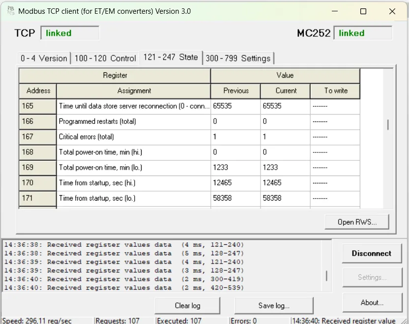
Modbus Interface ReferenceThe Overvis MC252 operates as a Modbus gateway, listening for Modbus TCP connections on port 502 (configurable). It supports connections from standard Modbus TCP client applications. Windows client software for basic testing is available for download here. Upon receiving a connection request, the MC252 checks its list of active clients. If the maximum list size (as per technical specifications) has not been reached, the new client is accepted. Once connected, the MC252 processes Modbus requests from the client. In RS-485 Slave Mode, it also accepts requests from a Modbus Master on the RS-485 bus. Request ProcessingSection titled “Request Processing”The device analyzes each request based on the requested function and the client’s access rights (determined by passwords entered).
If a valid response is received, the MC252 forwards it back to the client. TroubleshootingSection titled “Troubleshooting”
SMS Modbus AccessSection titled “SMS Modbus Access”With an active SIM card, the MC252 can process Modbus requests via SMS. SMS FormatSection titled “SMS Format”Incoming SMS messages are checked for a valid Modbus request format.
Request Syntax:
Examples:
SMS ResponsesSection titled “SMS Responses”The MC252 sends a response SMS upon processing the Modbus request command.
Table 1 - Standard Modbus Exception Codes
Configuration via ModbusSection titled “Configuration via Modbus”The MC252 can be configured using any Modbus TCP client.
Managing SettingsSection titled “Managing Settings”In Setup Mode, you can modify the Changeable Settings registers.
MC252 ParametersSection titled “MC252 Parameters”Table 2 - Parameter Data Formats
Table 3 - Parameter Groups
Device Description ParametersSection titled “Device Description Parameters”Table 4 - Device Description Parameters
Current Mode ParametersSection titled “Current Mode Parameters”Table 5 - Current Mode Parameters
Table 5.1 - Control Commands (Register 120)
Current Status ParametersSection titled “Current Status Parameters”Table 6 - Current Status Parameters
Table 6.1 - Tabs of Access Bits (Register 122)
Table 6.2 - Reset Causes Bits (Register 945)
Table 6.3 - Firmware Download Status Bits (Register 2004)
Settings ParametersSection titled “Settings Parameters”Table 7 - Settings Parameters
Table 7.1 - RS-485 Byte Formats (Register 461)
Table 7.2 - Cloud Server Connection Modes (Register 465)
Table 7.3 - Remote Server Connection Modes (Register 647)
Table 7.4 - Daylight Saving Time Transition Modes (Register 700)
Q: What is the default Modbus TCP port and device address? A: MC252 listens on TCP port 502 (configurable in register 450) and uses Modbus address 111 by default (configurable in register 457). You can view the current IP address by pressing the Q: How do I enter Setup Mode to change configuration? A: Write the password (found on the device label) to registers 100-119. If correct, register 121 will read Q: How do I save my configuration changes? A: Write command Q: I have saved the new settings, how do I restart MC252 remotely? A: Write command Q: How do I configure RS-485 communication parameters? A: Key registers are:
Q: What is the difference between Master and Slave RS-485 modes? A: In Modbus Master mode (default), MC252 sends queries to RS-485 devices. In Modbus Slave mode, MC252 receives queries from an external Modbus Master on RS-485. Use Slave mode when MC252 should act as a slave device on an existing RS-485 network. **Q: I have configured RS-485 and set MC252 modbus device ID parameter to match my RS-485 device address. But I still get errors like A: This can happen because MC252 (configured this way) reads its own virtual Modbus device registers instead of redirecting the requests to your RS-485 device. Do not set virtual Modbus ID in the Q: How can I connect the RS-485 device if its protocol differs from Modbus? A: Select Tunnel mode for RS-485. You may also need to select the tunnel for either the MC252 server or one of the remote servers connections. Q: How do I send Modbus commands via SMS? A: Format: Q: How do I set the device clock via Modbus? A: First, write command Q: How can I connect MC252 to multiple remote Modbus TCP servers? A: MC252 supports up to 3 remote TCP servers. Configure each in registers 640-649 (first), 760-769 (second), and 770-779 (third). The main parameters are the connection mode and the server IP address. Also, set Modbus ID range for each server to avoid extra traffic and delays. Q: What does the “virtual identifiers” option do for remote servers? A: When enabled (register 647 for the first remote server, values 5-8), MC252 remaps Modbus addresses before forwarding. The range is renumbered starting from 1. For example, if range is 15-17, address 16 becomes 2 on the remote server. This helps to avoid address conflicts, when multiple gateways share address space, or when multiple Modbus TCP devices of the same model are connected. Q: How do I reset the device to factory defaults? A: Enter Setup Mode by writing the password, then write command Q: Why can’t I read certain status registers? A: Some registers (like GSM IP address, register 900-903) are only available after the authentication. Enter the password first. Also, the clock setting registers (34817-34825) require Clock Setting Mode. Q: How do I check the current firmware version? A: Read register 1 for the firmware version number. Need Help?Section titled “Need Help?”For technical support and assistance:
FootnotesSection titled “Footnotes”
|
| | |||||||||||||||||||||||||||||||||||||||||||||||||||||||||||||||||||||||||||||||||||||||||||||||||||
|---|---|---|---|---|---|---|---|---|---|---|---|---|---|---|---|---|---|---|---|---|---|---|---|---|---|---|---|---|---|---|---|---|---|---|---|---|---|---|---|---|---|---|---|---|---|---|---|---|---|---|---|---|---|---|---|---|---|---|---|---|---|---|---|---|---|---|---|---|---|---|---|---|---|---|---|---|---|---|---|---|---|---|---|---|---|---|---|---|---|---|---|---|---|---|---|---|---|---|---|
Memory Card Data SavingThe Overvis MC252 supports microSD compatible memory cards formatted as FAT/FAT32. Only the first volume of the card is used (the maximum usable capacity on the card is 32 GB). The card can be inserted before powering the device or while the device is in operation. MC252 uses a memory card for the following actions:
When the device is started or when a memory card is inserted, its parameters are checked (it may take up to 3 seconds). After that, the card can be used for other actions. When the device is restarted, or when the supply voltage drops below the value specified in the settings (see Modbus Register Map, register 724), MC252 safely unmounts the memory card. Before unmounting, temporary data is saved and files are closed. Taskfiles operationsSection titled “Taskfiles operations”MC252 performs several operations with taskfiles in the
See Logic Programming for details on files in the Logging of collected dataSection titled “Logging of collected data”MC252 saves the collected data to the log in the
For each month, a subfolder is created with a name in the format
In this subfolder, for each day of the month, a file is created with the name in the format
The data is appended to the end of the current file. A new file with the next index is created when one or more of the following conditions are met:
File IndexingSection titled “File Indexing”Before creating the file, the presence of files in the subfolder with names for the given day of the month is checked, and the maximum occupied index is found.
Files are numbered starting from
In total, up to 1035 indexes can be used for one day of the month. After that, recording is suspended until the date changes. Log FormatsSection titled “Log Formats”When the binary log format is selected, the MC252 saves the collected data in a compact form into files with the Table 1 - Format of the service record in the log data bytes file
Table 2 - Format of parameter recording in the log data bytes file
When the text table log format is selected, MC252 saves the collected data in text form into files with the
Table 3 – Format of records in the file of text tables of the log
Filling the memory cardSection titled “Filling the memory card”The time it takes for an empty memory card to be filled, can be calculated using the formula: , where:
Examples:
Diagnostic loggingSection titled “Diagnostic logging”MC252 can be configured to store diagnostic logs into the
Export and import settingsSection titled “Export and import settings”MC252 can export the saved settings from the internal memory to the
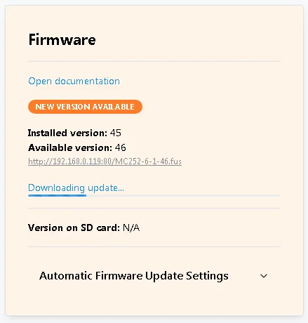
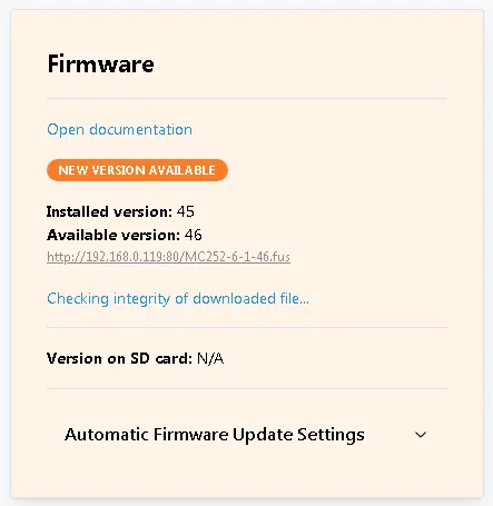
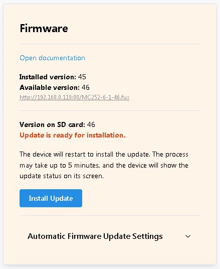
Firmware updatesSection titled “Firmware updates”MC252 can update the firmware (see Firmware Update) with one of three files:
MC252 uses the The file size can be up to 10 MB each in size. Q: What type of memory card does MC252 support? A: MC252 supports microSD compatible memory cards formatted as FAT or FAT32. Only the first volume is used, with a maximum usable capacity of 32 GB. Q: Can I insert or remove the memory card while the device is running? A: You can insert the card while the device is running. However, removing the card during operation may result in data loss. To safely remove the card, wait until after a device reset while the device title is displayed on screen. Q: What happens if the power supply drops while the card is in use? A: MC252 monitors supply voltage and safely unmounts the memory card when voltage drops below a configurable threshold (register 724). Before unmounting, temporary data is saved and files are closed to prevent corruption. A high-capacitive power supply is recommended to give enough time for this feature. Q: Which log format should I use — binary (.DAT) or text (.CSV)? A:
Q: How long will it take to fill my memory card with log data? A: Use the formula: Q: What happens when the memory card is full? A: It depends on the recorder mode setting (register 727). When enabled, the oldest files are automatically deleted to make room for new data. When disabled, logging pauses until you manually free up space. Q: How much data can be logged per day? A: The file size limit is configurable (up to 64Mb). And up to 1035 files per day can be created in the day folder. After all file indices are used, recording is suspended until the date changes. Q: What happens if a write error occurs during logging? A: Data remains in a temporary write queue and the device retries for up to 10 minutes. If writing still fails, the data is removed from the queue and the number of lost bytes is recorded for reporting in subsequent log entries. Q: Can I use the same memory card for multiple MC252 devices? A: Yes, but be careful with taskfiles — each device will try to load and execute taskfiles from the Q: Where are taskfile compilation results stored? A: In the same
Q: How do I back up my MC252 settings to the memory card? A: Export settings to the Q: Why does the SD card take up to 3 seconds to become available after insertion? A: MC252 performs parameter checks on the card after insertion or device startup. This verification ensures the card is properly formatted and usable. Need Help?Section titled “Need Help?”For technical support and assistance:
|
| | ||||||||||||||||||||||||||||||||||||||||||||||||||||||||||||||||||||||||||||||||||||||||||||||||||||||||||||||||||
|---|---|---|---|---|---|---|---|---|---|---|---|---|---|---|---|---|---|---|---|---|---|---|---|---|---|---|---|---|---|---|---|---|---|---|---|---|---|---|---|---|---|---|---|---|---|---|---|---|---|---|---|---|---|---|---|---|---|---|---|---|---|---|---|---|---|---|---|---|---|---|---|---|---|---|---|---|---|---|---|---|---|---|---|---|---|---|---|---|---|---|---|---|---|---|---|---|---|---|---|---|---|---|---|---|---|---|---|---|---|---|---|---|---|---|
HTTP APIThis HTTP API provides an interface for interacting with the Overvis MC252 device. All requests are made to paths starting with General PrinciplesSection titled “General Principles”
AuthorizationSection titled “Authorization”Authorization via APISection titled “Authorization via API”To perform protected requests, you must complete the authorization procedure:
Logout is performed via Authorization via Front Panel ButtonSection titled “Authorization via Front Panel Button”Press the button on the front panel of the MC252 device once. After this, a user with Guest rights temporarily receives access level 🟨 1 (Power User) for 10 minutes. Authorization via VPN CloudSection titled “Authorization via VPN Cloud”All requests coming from the VPN cloud automatically receive access level 🟥 2 — Administrator. Endpoints SummarySection titled “Endpoints Summary”GET RequestsSection titled “GET Requests”
POST RequestsSection titled “POST Requests”
|
| | |||||||||||||||||||||||||||
|---|---|---|---|---|---|---|---|---|---|---|---|---|---|---|---|---|---|---|---|---|---|---|---|---|---|---|---|
AuthenticationGet Salt for Password HashingSection titled “Get Salt for Password Hashing”Provides a unique GET Response:
Example Response: User AuthenticationSection titled “User Authentication”Allows a user to authenticate and receive an access token. POST Request Parameters:
Note: SHA1 password hash is calculated as SHA1( Example Request: Response: Upon successful authentication, a token and its expiration time are returned.
LogoutSection titled “Logout”Ends the current user session and invalidates the token. POST Example Request: Response: Empty JSON upon successful command execution. |
| | ||||||||||||||||||||||||||||||||||||||||||||||||||||||||||||||||||||||||||||||||||||||||||||||||||||||||||||||||||||||||||||||||||||||||||||||||||||||||||||||||||||||||||||||||||||||||||||||||||||||||||||||||||||||||||||||||||||||||||||||||||||||||||||||||||||||||||||||||||||||||||||||||||||||||||||||||||||||||||||||||||||||||||||||||||||||||||||||||||||||||||||||||||||||||||||||||||||||||||||||||||||||||||||||||||||||||||||||||||||||||||||||||||||||||||||||||||||||||||||||||||||||||||||||||||||||||||||||||||||||||||||||||||||||||||||||||||||||||||||||||||||||||||||||||||||||||||||||||||||||||||||||||||||||||||||||||||||||||||||||||||||||||||||||||||||||||||||||||||||||||||||||||||||||||||||||
|---|---|---|---|---|---|---|---|---|---|---|---|---|---|---|---|---|---|---|---|---|---|---|---|---|---|---|---|---|---|---|---|---|---|---|---|---|---|---|---|---|---|---|---|---|---|---|---|---|---|---|---|---|---|---|---|---|---|---|---|---|---|---|---|---|---|---|---|---|---|---|---|---|---|---|---|---|---|---|---|---|---|---|---|---|---|---|---|---|---|---|---|---|---|---|---|---|---|---|---|---|---|---|---|---|---|---|---|---|---|---|---|---|---|---|---|---|---|---|---|---|---|---|---|---|---|---|---|---|---|---|---|---|---|---|---|---|---|---|---|---|---|---|---|---|---|---|---|---|---|---|---|---|---|---|---|---|---|---|---|---|---|---|---|---|---|---|---|---|---|---|---|---|---|---|---|---|---|---|---|---|---|---|---|---|---|---|---|---|---|---|---|---|---|---|---|---|---|---|---|---|---|---|---|---|---|---|---|---|---|---|---|---|---|---|---|---|---|---|---|---|---|---|---|---|---|---|---|---|---|---|---|---|---|---|---|---|---|---|---|---|---|---|---|---|---|---|---|---|---|---|---|---|---|---|---|---|---|---|---|---|---|---|---|---|---|---|---|---|---|---|---|---|---|---|---|---|---|---|---|---|---|---|---|---|---|---|---|---|---|---|---|---|---|---|---|---|---|---|---|---|---|---|---|---|---|---|---|---|---|---|---|---|---|---|---|---|---|---|---|---|---|---|---|---|---|---|---|---|---|---|---|---|---|---|---|---|---|---|---|---|---|---|---|---|---|---|---|---|---|---|---|---|---|---|---|---|---|---|---|---|---|---|---|---|---|---|---|---|---|---|---|---|---|---|---|---|---|---|---|---|---|---|---|---|---|---|---|---|---|---|---|---|---|---|---|---|---|---|---|---|---|---|---|---|---|---|---|---|---|---|---|---|---|---|---|---|---|---|---|---|---|---|---|---|---|---|---|---|---|---|---|---|---|---|---|---|---|---|---|---|---|---|---|---|---|---|---|---|---|---|---|---|---|---|---|---|---|---|---|---|---|---|---|---|---|---|---|---|---|---|---|---|---|---|---|---|---|---|---|---|---|---|---|---|---|---|---|---|---|---|---|---|---|---|---|---|---|---|---|---|---|---|---|---|---|---|---|---|---|---|---|---|---|---|---|---|---|---|---|---|---|---|---|---|---|---|---|---|---|---|---|---|---|---|---|---|---|---|---|---|---|---|---|---|---|---|---|---|---|---|---|---|---|---|---|---|---|---|---|---|---|---|---|---|---|---|---|---|---|---|---|---|---|---|---|---|---|---|---|---|---|---|---|---|---|---|---|---|---|---|---|---|---|---|---|---|---|---|---|---|---|---|---|---|---|---|---|---|---|---|---|---|---|---|---|---|---|---|---|---|---|---|---|---|---|---|---|---|---|---|---|---|---|---|---|---|---|---|---|---|---|---|---|---|---|---|---|---|---|---|---|---|---|---|---|---|---|---|---|---|---|---|---|---|---|---|---|---|---|---|---|---|---|---|---|---|---|---|---|---|---|---|---|---|---|---|---|---|---|---|---|---|---|---|---|---|---|---|---|---|---|---|
System InformationPhysical Device IdentificationSection titled “Physical Device Identification”Returns unique information about the current device, including model, firmware version, MAC address, and public key. GET Access Level: 🟨 1 Response:
Example Response: Firmware VersionSection titled “Firmware Version”GET Access Level: 🟩 0 Response:
Example Response: Get Device StateSection titled “Get Device State”Retrieves the current state of the device by key (or all states). GET Access Level: 🟨 1 Available Keys:
ethernetSection titled “ethernet”Returns information about the current Ethernet connection state. Response Fields:
Returns information about the current GSM module state. Response Fields:
Returns information about the current VPN (WireGuard) connection state. Response Fields:
mbTcpCallbackSection titled “mbTcpCallback”Modbus TCP cloud connection state. Response Fields:
activationSection titled “activation”Returns information about the current device activation state. Response Fields:
fwUpdateSection titled “fwUpdate”Firmware update process state. Response Fields:
mbTcpServerSection titled “mbTcpServer”List of active Modbus TCP server connections. Response Fields:
mbTcpClientsSection titled “mbTcpClients”State of Modbus TCP clients. Response Fields:
inputsSection titled “inputs”Example Request:
Example Response: outputsSection titled “outputs”Example Request:
Example Response: statisticsSection titled “statistics”Device operation statistics. Response Fields:
memTaskfilesSection titled “memTaskfiles”Task files and programmable logic state information. Example Request:
Response Fields:
Compilation Error Codes:
Task Object Fields:
Task Execution Error Codes:
Example Response: memCardSection titled “memCard”SD card state information. Response Fields:
settingsSection titled “settings”Settings state information. Response Fields:
Current device time information. Response Fields:
Additional diagnostic data. Response Fields:
Last Reset Causes Flags:
|
| | |||||||||||||||||||||||||||||||||||||||||||||||||||||||||||||||||||||||||||||||||||||||||||||||||||||||||||||||||||||||||||||||||||||||||||||||||||||||||||||||||||||||||||||||||||||||||||||||||||||||||||||||||||||||||||||||||||||||||||||||||||||||||||||||||||||||||||||||||||||||||||||||||||||||||||||||||||||||||||||||||||||||||||||||||||||||||||||||||||||||||||||||||||||||||||||||||||||||||||||||||||||||||||||||||||||||||||||||||||||||||||||||||||||||||||||||||||||||||||||||||||||||||||||||||||||||||||||||||||||||||||||||||||||||||||||||||||||||||||||||||||||||||||||||||||||||||||||||||||||||||||||||||||||||||||||
|---|---|---|---|---|---|---|---|---|---|---|---|---|---|---|---|---|---|---|---|---|---|---|---|---|---|---|---|---|---|---|---|---|---|---|---|---|---|---|---|---|---|---|---|---|---|---|---|---|---|---|---|---|---|---|---|---|---|---|---|---|---|---|---|---|---|---|---|---|---|---|---|---|---|---|---|---|---|---|---|---|---|---|---|---|---|---|---|---|---|---|---|---|---|---|---|---|---|---|---|---|---|---|---|---|---|---|---|---|---|---|---|---|---|---|---|---|---|---|---|---|---|---|---|---|---|---|---|---|---|---|---|---|---|---|---|---|---|---|---|---|---|---|---|---|---|---|---|---|---|---|---|---|---|---|---|---|---|---|---|---|---|---|---|---|---|---|---|---|---|---|---|---|---|---|---|---|---|---|---|---|---|---|---|---|---|---|---|---|---|---|---|---|---|---|---|---|---|---|---|---|---|---|---|---|---|---|---|---|---|---|---|---|---|---|---|---|---|---|---|---|---|---|---|---|---|---|---|---|---|---|---|---|---|---|---|---|---|---|---|---|---|---|---|---|---|---|---|---|---|---|---|---|---|---|---|---|---|---|---|---|---|---|---|---|---|---|---|---|---|---|---|---|---|---|---|---|---|---|---|---|---|---|---|---|---|---|---|---|---|---|---|---|---|---|---|---|---|---|---|---|---|---|---|---|---|---|---|---|---|---|---|---|---|---|---|---|---|---|---|---|---|---|---|---|---|---|---|---|---|---|---|---|---|---|---|---|---|---|---|---|---|---|---|---|---|---|---|---|---|---|---|---|---|---|---|---|---|---|---|---|---|---|---|---|---|---|---|---|---|---|---|---|---|---|---|---|---|---|---|---|---|---|---|---|---|---|---|---|---|---|---|---|---|---|---|---|---|---|---|---|---|---|---|---|---|---|---|---|---|---|---|---|---|---|---|---|---|---|---|---|---|---|---|---|---|---|---|---|---|---|---|---|---|---|---|---|---|---|---|---|---|---|---|---|---|---|---|---|---|---|---|---|---|---|---|---|---|---|---|---|---|---|---|---|---|---|---|---|---|---|---|---|---|---|---|---|---|---|---|---|---|---|---|---|---|---|---|---|---|---|---|---|---|---|---|---|---|---|---|---|---|---|---|---|---|---|---|---|---|---|---|---|---|---|---|---|---|---|---|---|---|---|---|---|---|---|---|---|---|---|---|---|---|---|---|---|---|---|---|---|---|---|---|---|---|---|---|---|---|---|---|---|---|---|---|---|---|---|---|---|---|---|---|---|---|---|---|---|---|---|---|---|---|---|---|---|---|---|---|---|---|---|---|---|---|---|---|---|---|---|---|---|---|---|---|---|---|---|---|---|---|---|---|---|---|---|---|---|---|---|---|---|---|---|---|---|---|---|---|---|---|
SettingsGet SettingsSection titled “Get Settings”Read settings from
GET Access Level: 🟨 1 Example Response: Set SettingsSection titled “Set Settings”Write settings to the POST Access Level: 🟨 1 Example Request: Response: Empty JSON upon success. Available Settings KeysSection titled “Available Settings Keys”The following keys can be used with
timeGmtSection titled “timeGmt”Time zone management (GMT offset). Request Parameters:
Example Request: Note: 8 means +2 hours offset (8 × 15 minutes). ethernetSection titled “ethernet”Ethernet interface settings. Request Parameters:
Example Request: GSM module settings. Request Parameters:
Example Request: ownSrvSection titled “ownSrv”Connection to own server. New values of these parameters take effect immediately after they are written by an API request. Request Parameters:
Example Request: wgCloudSection titled “wgCloud”Cloud VPN connection settings. Request Parameters:
Example Request: wgManualSection titled “wgManual”Custom WireGuard VPN settings. Request Parameters:
Example Request: cbCloudSection titled “cbCloud”Cloud Modbus connection settings. Request Parameters:
Example Request: aresetSection titled “areset”Automatic reset settings. Request Parameters:
Example Request: protectSection titled “protect”Device protection parameters. Request Parameters:
Example Request: downloadSection titled “download”File server settings. Request Parameters:
Example Request: firmwareSection titled “firmware”Firmware management. Request Parameters:
Example Request: Built-in HTTP server parameters. Request Parameters:
Example Request: languageSection titled “language”Interface language code. Note: If the display does not support the specified code, English will be used. Request Parameters:
Example Request: serialSection titled “serial”Serial interface settings. New values of these parameters take effect immediately after they are written by an API request. Request Parameters:
Example Request: Astronomical settings (sunrise/sunset). Request Parameters:
Example Request: NTP time synchronization settings. Request Parameters:
Example Request: tsModeSection titled “tsMode”Daylight saving time mode. Request Parameters:
Example Request: tsManualSection titled “tsManual”Manual daylight saving time settings. Request Parameters:
Example Request: logFlagsSection titled “logFlags”Logging settings. Request Parameters:
Example Request: TCP client settings (Remote Servers). New values of these parameters take effect immediately after they are written by an API request. Request Parameters:
Example Request: forwardingSection titled “forwarding”Port forwarding settings (Ethernet to GSM only). Request Parameters:
Example Request: tasksLoggingSection titled “tasksLogging”Programmable logic data logging settings. Note: Logging is only available when an SD card is installed. Request Parameters:
Example Request: powerSavingSection titled “powerSaving”Power and resource saving settings. Request Parameters:
Example Request: Export SettingsSection titled “Export Settings”Saves settings to a file in the root folder POST Request Parameters:
Example Request: Import SettingsSection titled “Import Settings”Loads settings from a file in the root folder POST Request Parameters:
Example Request: Reset SettingsSection titled “Reset Settings”Resets all device settings to default values. POST Example Request: |
| | |||||||||||||||||||||||||||||||||||||||||||||||||||
|---|---|---|---|---|---|---|---|---|---|---|---|---|---|---|---|---|---|---|---|---|---|---|---|---|---|---|---|---|---|---|---|---|---|---|---|---|---|---|---|---|---|---|---|---|---|---|---|---|---|---|---|
System CommandsReboot DeviceSection titled “Reboot Device”Initiates a delayed device reboot. POST Request Parameters:
Example Request: Set TimeSection titled “Set Time”Sets the device time immediately. POST Request Parameters:
Example Request: Sync TimeSection titled “Sync Time”Immediately synchronizes device time with NTP servers specified in settings. POST Example Request: Activate LicenseSection titled “Activate License”Sends an activation request via WireGuard interface. Supported only with active WireGuard connection. POST Request Parameters:
|
| |
|---|
UpdatesCheck for UpdatesSection titled “Check for Updates”Initiates a check for available updates (firmware) on the server. POST Example Request: Download UpdatesSection titled “Download Updates”Initiates download of available updates (firmware). SD card must be installed. POST Example Request: Program UpdateSection titled “Program Update”Initiates installation of a previously downloaded update (firmware) from the SD card. POST Example Request: |
| | ||||||
|---|---|---|---|---|---|---|
GSMSend Test SMSSection titled “Send Test SMS”Sends a test SMS message to the specified phone number via the GSM modem. POST Request Parameters:
Example Request: |
| | ||||||||||||||||||||||||||||||||||||||||||||||||||||||||||||||||||||||||||||||||||||||||||||||||||||||||||||||||||||||||||||||||||||||||||||||||||||||||||||||||||||||||||||||||||||||||||||||||||||||||||||||||||||||||||||||||||||||||||||||||||||||||||||||||||||||||||||||||||
|---|---|---|---|---|---|---|---|---|---|---|---|---|---|---|---|---|---|---|---|---|---|---|---|---|---|---|---|---|---|---|---|---|---|---|---|---|---|---|---|---|---|---|---|---|---|---|---|---|---|---|---|---|---|---|---|---|---|---|---|---|---|---|---|---|---|---|---|---|---|---|---|---|---|---|---|---|---|---|---|---|---|---|---|---|---|---|---|---|---|---|---|---|---|---|---|---|---|---|---|---|---|---|---|---|---|---|---|---|---|---|---|---|---|---|---|---|---|---|---|---|---|---|---|---|---|---|---|---|---|---|---|---|---|---|---|---|---|---|---|---|---|---|---|---|---|---|---|---|---|---|---|---|---|---|---|---|---|---|---|---|---|---|---|---|---|---|---|---|---|---|---|---|---|---|---|---|---|---|---|---|---|---|---|---|---|---|---|---|---|---|---|---|---|---|---|---|---|---|---|---|---|---|---|---|---|---|---|---|---|---|---|---|---|---|---|---|---|---|---|---|---|---|---|---|---|---|---|---|---|---|---|---|---|---|---|---|---|---|---|---|---|---|---|---|---|---|---|---|---|---|---|---|---|---|---|---|---|---|---|---|---|---|---|---|---|---|---|---|---|---|---|---|---|---|
ModbusFind Modbus DevicesSection titled “Find Modbus Devices”Starts searching for Modbus devices on the RS-485 bus. POST Request Parameters:
Example Request: Stop SearchSection titled “Stop Search”Stops the active Modbus device search. POST Response:
Get Search ResultSection titled “Get Search Result”Returns the list of found devices. GET Request Parameters:
Response:
Template Search and IdentificationSection titled “Template Search and Identification”Get META Info from TemplateSection titled “Get META Info from Template”POST Request Parameters:
Example Request: Response:
Start Search by TemplateSection titled “Start Search by Template”POST Request Parameters:
Example Request: Response:
Stop Template SearchSection titled “Stop Template Search”POST Response:
Get Search ResultSection titled “Get Search Result”GET Response:
Template Search Error CodesSection titled “Template Search Error Codes”
Modbus Request/ResponseSection titled “Modbus Request/Response”Send Modbus RequestSection titled “Send Modbus Request”POST Request Parameters:
Example Request: Response:
Get Modbus ResponseSection titled “Get Modbus Response”GET Request Parameters:
Response:
Reconnect to Cloud via ModbusSection titled “Reconnect to Cloud via Modbus”Disconnects and reconnects to the cloud server. POST Request Parameters:
Example Request: |
| | |||||||||||||||||||||||||||||||||||||||||||||||||||||||||||||||||||||||||||||||||||||||||||||||||||||||||||||||||
|---|---|---|---|---|---|---|---|---|---|---|---|---|---|---|---|---|---|---|---|---|---|---|---|---|---|---|---|---|---|---|---|---|---|---|---|---|---|---|---|---|---|---|---|---|---|---|---|---|---|---|---|---|---|---|---|---|---|---|---|---|---|---|---|---|---|---|---|---|---|---|---|---|---|---|---|---|---|---|---|---|---|---|---|---|---|---|---|---|---|---|---|---|---|---|---|---|---|---|---|---|---|---|---|---|---|---|---|---|---|---|---|---|---|
SD CardList Files and DirectoriesSection titled “List Files and Directories”Returns a list of files and subdirectories. POST Request Parameters:
Example Request: Response:
Each item in
Example Response: Get File InfoSection titled “Get File Info”Returns metadata about a file. POST Request Parameters:
Example Request: Response:
Example Response: Download FileSection titled “Download File”Returns file as the HTTP response. This request supports GET Request Parameters:
Example Request: Response: The file contents are returned in the response. If the Read FileSection titled “Read File”Returns file data block in base64 encoding. POST Request Parameters:
Example Request: Response:
Example Response: Write FileSection titled “Write File”Uploads file data to SD card. POST Request Parameters:
Note: Data in blocks must be strictly 1024 bytes, except for the last block. Example Request: Response: Empty JSON on success. Remove FileSection titled “Remove File”Removes a file from the SD card. POST Request Parameters:
Example Request: Response: Empty JSON on success. Eject SD CardSection titled “Eject SD Card”Prepares SD card for safe removal. POST Example Request: Response: Empty JSON on success. |
| | ||||||||||||||||||||||||||||||
|---|---|---|---|---|---|---|---|---|---|---|---|---|---|---|---|---|---|---|---|---|---|---|---|---|---|---|---|---|---|---|
HTTP Status Codes
|
| | ||||||||||||||||||||||||||||||||||||||||||||||||||||||||||||||||||||||||||||||||||||||||||||||||||||||||||||||||||||||||||||||||||||||||||||||||||||||||||||
|---|---|---|---|---|---|---|---|---|---|---|---|---|---|---|---|---|---|---|---|---|---|---|---|---|---|---|---|---|---|---|---|---|---|---|---|---|---|---|---|---|---|---|---|---|---|---|---|---|---|---|---|---|---|---|---|---|---|---|---|---|---|---|---|---|---|---|---|---|---|---|---|---|---|---|---|---|---|---|---|---|---|---|---|---|---|---|---|---|---|---|---|---|---|---|---|---|---|---|---|---|---|---|---|---|---|---|---|---|---|---|---|---|---|---|---|---|---|---|---|---|---|---|---|---|---|---|---|---|---|---|---|---|---|---|---|---|---|---|---|---|---|---|---|---|---|---|---|---|---|---|---|---|---|---|---|---|
Operations Logic Programming ReferenceAfter running, Overvis MC252 starts execution of the operations logic program, if it was placed earlier in the internal memory. If there is no program in the internal memory, and a memory card is present (formatted as Files can have arbitrary names and extensions (except for The found correct files are read into the internal memory and they form the operations logic program. The internal logic memory can be cleared along with the settings reset to factory defaults. To preserve the settings and clear the internal logic memory only, you should use either Modbus or Web-interface command.
TaskfileSection titled “Taskfile”Taskfile describes set of actions repeated at a specified time interval. The actions can include gathering data, processing and comparing the values and special actions after fulfillment of the preset conditions (according to the processing results). File consists of lines. Each line can be one of the following:
Lines can include Taskfile optionsSection titled “Taskfile options”Options configure taskfile compilation or execution. Options start with Compilation optionsSection titled “Compilation options”
Section titled “PROTOCOLVERSION” |
| No. | Type | Description |
|---|---|---|
| 0 | UINT16 | unsigned (non-negative) 16-bit (2 bytes) integer, serialized as Big Endian (most significant byte first, e.g. 258 is stored as 0x01, 0x02); |
| 1 | INT16 | signed 16-bit (2 bytes) integer, serialized as Big Endian; |
| 2 | INT16BLE | signed 16-bit (2 bytes) integer, serialized as Little Endian (least significant byte first, e.g. 258 is stored as 0x02, 0x01); |
| 3 | INT32 | signed 32-bit (4 bytes) integer, serialized as Big Endian (most significant byte first, e.g. 66051 is stored as 0x00, 0x01, 0x02, 0x03); |
| 4 | INT32BLE | signed 32-bit (4 bytes) integer, with bytes serialized as Little Endian (least significant byte first, e.g. 66051 is stored as 0x03, 0x02, 0x01, 0x00); |
| 5 | INT32WLE | signed 32-bit (4 bytes) integer, with words serialized as Little Endian (least significant word first, e.g. 66051 is stored as 0x02, 0x03, 0x00, 0x01); |
| 6 | BIT | 1-bit integer (used for example to access Modbus coils and discrete inputs); |
| 7 | INT32BE | same as INT32 |
| 8 | F32EP0R | IEEE 754 single precision (4 bytes) floating-point, serialized as Big Endian; |
| 9 | F32BLEEP0R | IEEE 754 single precision (4 bytes) floating-point, with bytes serialized as Little Endian; |
| 10 | F32WLEEP0R | IEEE 754 single precision (4 bytes) floating-point, with words serialized as Little Endian; |
| 11 | F32EP1R | single precision (4 bytes) floating-point, serialized as divided by 10 Big Endian; |
| 12 | F32BLEEP1R | same as F32BLEEP0R, but divided by 10 before serializing; |
| 13 | F32WLEEP1R | same as F32WLEEP0R, but divided by 10 before serializing; |
| 14 | F32EP2R | single precision (4 bytes) floating-point, serialized as divided by 100 Big Endian; |
| 15 | F32BLEEP2R | same as F32BLEEP0R, but divided by 100 before serializing; |
| 16 | F32WLEEP2R | same as F32WLEEP0R, but divided by 100 before serializing; |
| 17 | F32EP3R | single precision (4 bytes) floating-point, serialized as divided by 1000 Big Endian; |
| 18 | F32BLEEP3R | same as F32BLEEP0R, but divided by 1000 before serializing; |
| 19 | F32WLEEP3R | same as F32WLEEP0R, but divided by 1000 before serializing; |
| 20 | UINT16BLE | unsigned (non-negative) 16-bit (2 bytes) integer, serialized as Little Endian; |
| 21 | UINT8 | unsigned (non-negative) 8-bit (1 byte) integer; |
| 22 | INT8 | signed 8-bit (1 byte) integer; |
Table 2 - Parameter types available for 64-bit variable type
| No. | Type | Description |
|---|---|---|
| 23 | UINT32 | unsigned (non-negative) 32-bit (4 bytes) integer, serialized as Big Endian (most significant byte first, e.g. 66051 is stored as 0x00, 0x00, 0x00, 0x00, 0x00, 0x01, 0x02, 0x03); |
| 24 | UINT32BLE | unsigned (non-negative) 32-bit (4 bytes) integer, with bytes serialized as Little Endian (least significant byte first, e.g. 66051 is stored as 0x03, 0x02, 0x01, 0x00, 0x00, 0x00, 0x00, 0x00); |
| 25 | UINT32WLE | unsigned (non-negative) 32-bit (4 bytes) integer, with words serialized as Little Endian (least significant word first, e.g. 66051 is stored as 0x02, 0x03, 0x00, 0x01, 0x00, 0x00, 0x00, 0x00); |
| 26 | INT64 | signed 64-bit (8 bytes) integer, serialized as Big Endian (most significant byte first, e.g. 66051 is stored as 0x00, 0x00, 0x00, 0x00, 0x00, 0x01, 0x02, 0x03); |
| 27 | INT64BLE | signed 64-bit (8 bytes) integer, with bytes serialized as Little Endian (least significant byte first, e.g. 66051 is stored as 0x03, 0x02, 0x01, 0x00, 0x00, 0x00, 0x00, 0x00); |
| 28 | INT64WLE | signed 64-bit (8 bytes) integer, with words serialized as Little Endian (least significant word first, e.g. 66051 is stored as 0x02, 0x03, 0x00, 0x01, 0x00, 0x00, 0x00, 0x00); |
| 29 | F64EP0R | IEEE 754 double precision (8 bytes) floating-point, serialized as Big Endian; |
| 30 | F64BLEEP0R | IEEE 754 double precision (8 bytes) floating-point, with bytes serialized as Little Endian; |
| 31 | F64WLEEP0R | IEEE 754 double precision (8 bytes) floating-point, with words serialized as Little Endian; |
| 32 | F64EP1R | double precision (8 bytes) floating-point, serialized as divided by 10 Big Endian; |
| 33 | F64BLEEP1R | same as F64BLEEP0R, but divided by 10 before serializing; |
| 34 | F64WLEEP1R | same as F64WLEEP0R, but divided by 10 before serializing; |
| 35 | F64EP2R | double precision (8 bytes) floating-point, serialized as divided by 100 Big Endian; |
| 36 | F64BLEEP2R | same as F64BLEEP0R, but divided by 100 before serializing; |
| 37 | F64WLEEP2R | same as F64WLEEP0R, but divided by 100 before serializing; |
| 38 | F64EP3R | double precision (8 bytes) floating-point, serialized as divided by 1000 Big Endian; |
| 39 | F64BLEEP3R | same as F64BLEEP0R, but divided by 1000 before serializing; |
| 40 | F64WLEEP3R | same as F64WLEEP0R, but divided by 1000 before serializing; |
| 41 | F64EP4R | double precision (8 bytes) floating-point, serialized as divided by 10000 Big Endian; |
| 42 | F64BLEEP4R | same as F64BLEEP0R, but divided by 10000 before serializing; |
| 43 | F64WLEEP4R | same as F64WLEEP0R, but divided by 10000 before serializing; |
| 44 | F64EP5R | double precision (8 bytes) floating-point, serialized as divided by 100000 Big Endian; |
| 45 | F64BLEEP5R | same as F64BLEEP0R, but divided by 100000 before serializing; |
| 46 | F64WLEEP5R | same as F64WLEEP0R, but divided by 100000 before serializing; |
| 47 | F64EP6R | double precision (8 bytes) floating-point, serialized as divided by 1000000 Big Endian; |
| 48 | F64BLEEP6R | same as F64BLEEP0R, but divided by 1000000 before serializing; |
| 49 | F64WLEEP6R | same as F64WLEEP0R, but divided by 1000000 before serializing; |
The type is followed by 1 or 3 arguments:
MEMTEMP, MEMBAT, MEMFILE, MEMFLASH (for memory areas) or a Modbus device defined earlier.C, D, H, I for coils, discrete inputs, holding registers or input registers respectively. For memory sources it is optional - if specified, it maps the memory parameter to own controller virtual device addresses.0..65535, or indirect as a variable plus integer value, e.g. some_variable+0). For memory sources it is optional - if specified, it maps the memory parameter to own controller virtual device addresses. Parameter may occupy several addresses depending on its type and size.Memory sources for the parameters allow to read presets or store settings and temporary values to be processed at consequtive runs.
MEMTEMP - RAM space, data is lost at powerdown or controller reset, small area size but excellent write speed;MEMBAT - memory area powered by internal clock battery, very limited size but good write speed;MEMFLASH - controller settings area, data retains at reset, small size and usually read-only;MEMFILE - extendable file area, requires memory card with the taskfiles to be present, average speed but excellent area size.Examples:
DEF local_time UINT32 mc_251 H 170 ; own controller registers 170..171DEF alg_mode UINT32 MEMTEMP H 5000 ; RAM value, mapped to own holding register 5000Variables are used to operate integer values. All variables have the same type, which is set in taskfile options.
Variables can be mostly defined automatically when first mentioned.
Some operations though (like ‘ISKNOWN’, copying, or array items assignment) require the variable to be defined earlier.
Variables are defined with VAR type.
Variable arrays are defined with VARS type followed by array size in range 1..65535 (array of a single variable is effectively the same as a simple variable).
There is one pre-defined variable: lasterror.
Error occurances write the error code to it.
It cannot be written like the other variables, but RAISE command effectively writes to it.
This variable can be used in error handlers for error-specific actions.
Examples:
DEF variable_1 VAR DEF array_with_5_items VARS 5Conditions are used to operate boolean values.
Conditions can be mostly defined automatically when first mentioned.
Some operations though (like ‘ISKNOWN’, copying or array items assignment) require the condition to be defined earlier.
Conditions are defined with COND type.
Condition arrays are defined with CONDS type followed by array size in range 1..65535 (array of a single condition is effectively the same as a simple condtion).
Examples:
DEF is_temperature_high CONDActions form iterative logic algorythm. Actions can be one of the following:
Actions are executed consequtively with these exceptions:
TRUE;GO, CALL, RETURN would jump to a label or return from the function call;RAISE or any error occurance would either jump to the error handler or stop this execution run due to an unhandled error;EXIT stops this execution run.There are 2 labels used as the main taskfile function definition:
run - each time the taskfile run is executed, the action labelled run is performed first (if there is no such label, the first action in the taskfile is the first to be performed);onerror - if an error occurs with no other handlers specified, a handler labelled onerror is used (if there is no such label, the error would be unhandled, see Error handling below).The action may in some cases reference the other items which were not defined earlier in the taskfile:
CALL, TRYCALL or GO before they are defined;SENDSMS, SMSRCVD, NOSMSRCVD, SYSLOG or PARAMLOG before they are defined;Assertions are actions producing some result data, which they store in one of the holding items (variable or condition).
Assertions start with a PUT followed by result target item name.
Then comes the function with the proper result type for this target (see Variable evaluation, Condition evaluation below).
If no function is specified, the argument is directly copied into target (this can also be used to get the items from the array indexed by the variable, or put them back).
Examples:
DEF numbers VARS 3PUT numbers[0] 0PUT numbers[1] 1PUT numbers[2] 2 ; numbers contains [0, 1, 2]PUT index 2PUT x numbers[index] ; x contains 2PUT var_mul_result MUL x 2 ; var_mul_result contains 4Checks are actions used for branching.
They skip the next action if their function (with condition result, that is boolean) produces FALSE or an unknown value.
Checks start with IF followed by the function with the condition result type (see Condition evaluation below).
If no function specified, the argument should be a condition name.
Examples:
PUT lesser 5PUT greater 3IF LE lesser greater ; LE 5 3 produces FALSE, for 5 <= 3 is not trueGO then_section ; this command will not be executed; else sectionPUT tmp lesser ; lesser and greater variables values exchangePUT lesser greaterPUT greater tmpGO endif_sectionthen_section:; two variables already sorted, nothing to doendif_section:; two variables are sorted now, lesser <= greaterCommands are actions producing no result data or discarding it.
Commands are one of the following:
EXIT - stops taskfile execution. Has 1 argument: error name, OK (if no error) or lasterror.RAISE - forces an error occurance. Has 1 argument: error name, or lasterror (for raising the same error higher).GO - next action will not be performed, execution will continue from the specified label. Has 1 argument: label name.CALL - starts some user function execution. Next action execution is postponed, execution will now continue from the specified label. Has 1 argument - function entry label name.TRYCALL - starts some user function with its own error handling. Next action execution is postponed, execution will now continue from the specified label. Has 2 arguments - function entry label label name and error handler label name.RETURN - ends user function execution. Next action will not be performed, execution will continue from the previously postponed action (by the previously met ‘CALL’).WRITE - outputs data to the parameter. Has 2 arguments: parameter name, then variable name or an integer value.PARAMLOG - writes the parameter to the data log with a comment. Has 2 arguments: parameter name, then string name. The parameter must be in Modbus registers or otherwise mapped to Modbus, as its address is used in logs.PARAMLOGNOCOMMENT - writes the parameter to the data log without a comment. Has 1 argument: parameter name. The parameter must be in Modbus registers or otherwise mapped to Modbus, as its address is used in logs.SYSLOG - writes the string to the system log. Has 1 argument: the string name.SENDSMS - sends the string as an SMS. Has 2 arguments: the addressee string, then the SMS text string name. If the addressee strings results in no other characters than 0, the SMS would not be sent.Examples:
WRITE param_hysteresis 5 EXIT OKVariable evaluation functions are used in assertion action (PUT) to calculate a new variable value.
They can produce numeric value or an unknown result (see Unknown values below).
Most of the following functions take 2 arguments (e.g. a and b) and perform an operation.
ADD - addition (a + b). The first argument is variable, the second can be either variable or an integer value.
SUB - subtraction (a - b). The first argument is variable, the second can be either variable or an integer value.
MUL - multiplication (a * b). The first argument is variable, the second can be either variable or an integer value.
DIV - division (a / b, integer result). The first argument is variable, the second can be either variable or an integer value.
MOD - remainder of division (a - (a / b * b)). The first argument is variable, the second can be either variable or an integer value.
SQRT - square root (integer). Takes a single variable or an integer value argument.
VAL - direct copy. Takes a single argument: variable or an integer value. As with the other direct copying evaluations, function name VAL can be omitted.
Most of the following functions take 2 arguments (e.g. a and b) and perform an operation.
BITSAND - logical AND of every bit of a with the corresponding bit of b. The first argument is variable, the second can be either variable or an integer value.
BITSOR - logical OR of every bit of a with the corresponding bit of b. The first argument is variable, the second can be either variable or an integer value.
SHR - arithmetic shift to the right of the bits of a, b times right. The first argument is variable, the second can be either variable or an integer value.
SHL - shift to the left of the bits of a, b times left. The first argument is variable, the second can be either variable or an integer value.
BITSBIT - bit b copy out of the bits of a. Is equivalent to SHR a b followed by BITSAND a 1. The first argument is variable, the second can be either variable or integer value.
BITSNOT - bits inversion. Takes a single variable or an integer value argument.
READ - takes parameter as an argument, and reads then casts its value to the variable default type.MAX - maximal item of the array. Takes a single argument: array of variables.MAXIDX - index of the maximal item of the array in range of 0 to array size minus 1. Takes a single argument: array of variables.MIN - minimal item of the array. Takes a single argument: array of variables.MINIDX - index of the minimal item of the array in range of 0 to array size minus 1. Takes a single argument: array of variables.SUM - sum of the array items. Takes a single argument: array of variables.SELECTBY - takes 2 arguments: array of variables and array of conditions of the same size, and selects the variable corresponding to the first condition which is TRUE.GETUPDPERIODSEC - Task update period in seconds. No arguments.GETUPDPERIODMS - Task update period in milliseconds. No arguments.GETUPDNAMEIDX - first integer in the taskfile name. This can be used as a base or a factor for parameters mapping, to create several similar tasks with the same contents. No arguments.GETRTC - Real time clock in seconds (since base year, usually 2000). Local, with DST. No arguments.GETYEAR - Clock year. No arguments.GETMONTH - Clock month, 1 to 12. No arguments.GETDAY - Clock day of month, 1 to 31. No arguments.GETHOURS - Clock hours. No arguments.GETMINUTES - Clock minutes, 0 to 59. No arguments.GETSECONDS - Clock seconds, 0 to 59. No arguments.GETDOW - Clock day of week, 0 to 6, with 0 for Monday, 6 for Sunday. No arguments.GETDAYTIME - Day seconds, 0 to 86399. No arguments.GETSUNRISE - Day sunrise second, -1 to 86400, with -1 for polar day, 86400 for polar night. No arguments.GETSUNSET - Day sunset second, -1 to 86400, with -1 for polar day, 86400 for polar night. No arguments.GETVOLTAGE - Power supply voltage in millivolts. No arguments.GETTEMPERATURE - Temperature in degrees. No arguments.Examples:
PUT square MUL x x PUT uperiod GETUPDPERIODSEC PUT tdelay 10 ; 10 minutes delay PUT tdelay MUL tdelay 60 ; 10 minutes converted to seconds PUT counter DIV tdelay uperiod ; task reruns counter for 10 minutes periodCondition evaluation functions are used in either assertions (PUT actions) or checks (IF actions) to determine a condition value.
They can produce TRUE, FALSE or an unknown result (if referring the other unknown item values, see Unknown values below).
All functions come in direct or inversed form, which differ only in result being inverted or not before use.
The functions are listed in both forms, e.g. ‘EQ’ / ‘NE’ for equality and non-equality (inverted EQ) checks.
EQ / NE - equal / non-equal (a = b / a != b). The first argument is variable, the second can be either variable or an integer value.GE / LS - greater-or-equal / lesser (a >= b / a < b). The first argument is variable, the second can be either variable or an integer value.GR / LE - greater / lesser-or-equal (a > b / a <= b). The first argument is variable, the second can be either variable or an integer value.AND / NAND - logical AND / inverted logical AND (a && b / !(a && b)). Takes 2 condition arguments.OR / NOR - logical OR / inverted logical OR (a || b / !(a || b)). Takes 2 condition arguments.VAL / NOT - direct copy / inverted copy (a / !a). Takes a single argument: condition or boolean value (TRUE or FALSE). As with the other direct copying evaluations, function name VAL can be omitted.SMSRCVD / NOSMSRCVD - checks whether a new SMS starting with a specified text came from a number starting with specified digits. The first argument is a phone number start, the second is an SMS text start. If the phone number is an empty string, SMS from any abonents are checked.ISKNOWN / ISNOTKNOWN - checks whether the holding item value is known. Takes a single argument: variable or condition (the values are unknown if they are read from an uninitialized parameters or evaluated from the other unknown items, see Unknown values below).Examples:
  PUT c_equal EQ x 5  IF c_equal  EXIT OK
; the same function can be used in check directly IF EQ x 5 EXIT OKData processing is performed by variable evaluations which store values of integer type.
However, parameters read and write can cast data types from and to fractional values of single and double precision as defined in IEEE 754 standard. This casting can be done with a multiplier (depending on the parameter type used), to preserve a certain number of decimal digits of the value fractional part. Some connected devices may also have integer parameters representing a fractional value (pre-multiplied in a similar way as above).
This allows to operate fractional values as integers.
A care should be taken using operations like multiplication, division or square root.
For example, MUL 2 2 = 4, but if the first argument represents 0.2 value multiplied by 10, and the second - 0.02 value multiplied by 100 (fixed point values with 1 and 2 digit precision respectively), the result represents 0.004 multiplied by 1000 (10*100, as the multipliers were also multiplied).
A square root of the previous value (4 standing for a value 0.004 multiplied by 1000), SQRT 4 produces 2, which is a wrong result, because of the multiplier 1000. For SQRT 1000 is not an integer.
To get a correct result, this value multiplier should be adjusted to a nearest multiplier with even number of zeroes, that is 10000. So 4 should be pre-multiplied by 10 (producing 40 for 0.004 multiplied by 10000). Then the SQRT 40 produces 6 which is a correct result (standing for 0.06 multiplied by 100).
Holding items can be organized in arrays of fixed size.
Arrays should be defined before referencing them in evaluations (e.g. DEF some_array VARS 5 or DEF the_other_array CONDS 2).
There are 3 ways of using the arrays:
PUT some_array[3] MUL some_array[2] some_array[1]).PUT some_array[ar_idx] SQRT distance), b) or as an argument for a direct copying (including NOT function which is just an inverted copying of a condition, e.g. IF NOT c_array[counter]).Errors can occur during actions execution.
Some commands like CALL or RETURN result in error due to misusage, which requires program correction.
The other commands or functions result in error due to either wrong argument values (square root of a negative variable) or external reasons (e.g. parameter could not be read or written).
Error occurance in the function causes execution to interrupt and jump to the function error handler.
This can happen once per function call: if no handler has been provided, or another error occurs in the error handler itself, the execution continues at the caller function handler.
For the main taskfile function, onerror label is used as a default taskfile error handler.
A pre-defined variable lasterror can be used to read error code and perform error-specific actions.
If no caller handler is availbale, the error is considered unhandled - the default handler is performed similar to this:
SYSLOG default_err_msg EXIT lasterror ; DEF default_err_msg "Unhandled error #*VAR(lasterror)*: *ERR(lasterror)*"Error during the assertion usually causes the result target to have an unknown value.
Unknown values can also appear without an actual error, e.g. when reading an unitialized parameter or using the variable which has not been asserted.
Unknown values tend to spread, as most functions referring an unknown variable or condition value will result in an unknown value themselves.
Some functions may still determine the result, notwithstanding of unknown items in their arguments.
SELECTBY array function can get the result early (before reaching any of the unknown items later).
AND logical check can result in FALSE if any of its arguments is FALSE (while the other one can have any value), OR can likewise result in TRUE, etc.
Critical commands may require additional checks (ISKNOWN / ISNOTKNOWN) and direct variable assertions, or parameter initializations, to guard against unknown states.
IF check action treat unknown function result as FALSE, and would skip the next command.
This allows to choose between direct and inverted check function to guard the branch against executing in unknown states.
Below there are examples of finished programs, each consists of a single task file. To run the sample on the MC252 it is necessary to:
.txt extension) with program text.TASKS.This example describes a program that, in the event of fault of the device, will send SMS with warning.
In the taskfile text:
3 is Modbus ID of the device OM-310;240 is the register address which is monitored for the fault.# SMS sending when bit 0 of register 240 of device 3 is set
#12th version of Protocol@PROTOCOLVERSION 12#task rerun interval will be every 3 seconds@UPDATE 3#limit of response waiting for Modbus query is 1000 msec = 1 sec@PARAMTIMEOUT 1000#after each query the delay is added, equal to the response waiting time,#so the other clients can perform their queries@PARAMLOADRATIO 50
#MC252 can read and write no less than 120 registers per one query#note the * character - it is Modbus ID of the MC252 own virtual Modbus deviceDEF mc252 MBWRANY * 120 120#ОМ-310 has Modbus ID equal to 3 and allows reading 4 registers per one query,#but writing of only one register per one queryDEF om310 MBWRSINGLE 3 4
#during each update, it is required to read#the holding register with address 240 from OM-310#UINT16 – means that the 16-bit value is unsigned (it can’t be less than 0)DEF alarms UINT16 om310 H 240
#each run starts herePUT alarm READ alarms
#copy zero bit of the register 240PUT alarm BITSBIT alarm 0#now the variable holds the parameter 240.0 value 0 or 1
#variable is compared with 1, the condition produces `TRUE`, if alarm = 1PUT is_alarm EQ alarm 1#condition is met, if the previous condition is not fulfilled, and vice versaPUT no_alarm NOT is_alarm
#if the condition is_alarm is met (if 240.0 = 1), then send one SMSIF is_alarmSENDSMS technician_number alarm_msg
#program endEXIT OK
#SMS textDEF alarm_msg "OM-310 (3) – avaria"
#the phone to receive the SMS can be specified belowDEF technician_number "01234567"In this example, the program controls the hysteresis value on the second channel of the TR-101 device, depending on the temperature of the sensor on the first channel.
The program uses clock battery-powered memory as a storage of the temperature limits and corresponding hysteresis parameters. These parameters are mapped to the MC252 own registers to simplify program configuration.
In the taskfile text:
16 is Modbus ID of the device TR-101;4 is the address of the channel 1 temperature register;47 is the address of the channel 2 hysteresis reguster;5500 is the address for the lower temperature limit;5501 is the address for the upper temperature limit;5502 is the address for the hysteresis at crossing the lower temperature limit;5503 is the address for the hysteresis at crossing the upper temperature limit.@PROTOCOLVERSION 12@UPDATE 20 #program will run every 20 seconds@PARAMLOADRATIO 50
DEF mc252 MBSELF#TR-101 has Modbus ID 16 and can read no less than 100 registers per a query,#but write one register per one queryDEF tr101 MBWRSINGLE 16 100
#INT16 – registers with signed integers, as the temperature can be less than 0DEF t_lower INT16 MEMBAT H 5500DEF t_upper INT16 MEMBAT H 5501DEF t_chan1 INT16 tr101 H 4#UINT16 – as the hysteresis is no less than 0DEF h_at_lower UINT16 MEMBAT H 5502DEF h_at_upper UINT16 MEMBAT H 5503DEF h_chan2 UINT16 tr101 H 47
DEF temperatures VARS 3DEF hysteresi VARS 3DEF checks CONDS 3
#program startrun:
#lower and upper temperature limits, as well as its current valuePUT temperatures[0] READ t_lowerPUT temperatures[1] READ t_upperPUT temperatures[2] READ t_chan1
# hysteresis for temperatures that are below (or above) than the limitsPUT hysteresi[0] READ h_at_lowerPUT hysteresi[1] READ h_at_upper# current hysteresis valuePUT hysteresi[2] READ h_chan2
# was the temperature out of the limits?PUT checks[0] LE temperatures[2] temperatures[0]PUT checks[1] GE temperatures[2] temperatures[1]# in other cases - do not change the hysteresis (current value)PUT checks[2] TRUE
# the desired hysteresis is selected from hysteresi array# according to the conditions of checks arrayPUT hysteresis SELECTBY hysteresi checks
# is hysteresis not set to the desired value yet?IF NE hysteresis hysteresi[2]# write a new hysteresis to TR-101WRITE h_chan2 hysteresis
EXIT OKIn this example, a program is described that monitors the temperature measured by OB-215. When the temperature exceeds -15 degrees for more than 10 minutes, it sends an SMS and starts logging the temperature values.
In the taskfile text:
11 is Modbus ID of the OB-215 device;6 is the address of the register from which the temperature is read.@PROTOCOLVERSION 12# the program will run every 15 seconds@UPDATE 15DEF controller MBSELFDEF ob215 MBWRSINGLE 11 4DEF temperature INT16 ob215 H 6# alarm flag - temperature rise for more than 10 minutesDEF alarm_temp_high UINT16 MEMTEMP H 5000# counter for a delay of 10 minutes (600 seconds)DEF counter UINT16 MEMTEMP H 5001
run:PUT v_temp READ temperaturePUT v_alarm READ alarm_temp_high# v_alarm is auto-defined above as a variable# (by a PUT v_alarm READ construction)IF ISNOTKNOWN v_alarm PUT v_alarm 0PUT v_counter READ counterIF ISNOTKNOWN v_counter PUT v_counter 0PUT temp_limit -150
IF GR v_temp temp_limit GO noticed_temp_highWRITE alarm_temp_high 0WRITE counter 0EXIT OK
noticed_temp_high:PUT counter_limit 10PUT counter_limit MUL counter_limit 10IF GE v_counter counter_limit GO temp_high_too_longPUT v_period GETUPDPERIODSECPUT v_counter ADD v_counter v_periodWRITE counter v_counterEXIT OK
temp_high_too_long:# SMS should be sent only once -# (the flag v_alarm will become 1 at the next run)IF EQ v_alarm 0 SENDSMS phone1 txtWRITE alarm_temp_high 1PARAMLOG temperature txtEXIT OK
DEF txt "OB-215 (11) – avaria, tmp *VAR(v_temp)* > *VAR(temp_limit)*"DEF phone1 "01234567" ; phone number for the SMS can be specified hereQ: Where should I place my taskfiles on the SD card?
A: Place your taskfiles in the TASKS folder in the root of the SD card. The SD card must be formatted as FAT or FAT32. Files can have any name and extension except .OBJ, .MAP, .CNF (e.g., task.txt), and can also be organized in subfolders.
Q: How do I know if my taskfile has syntax errors?
A: When MC252 loads taskfiles, it checks them for errors. If errors are detected, the file won’t be loaded. You can check the loading status via the Web interface page Tasks, or Modbus registers (see Modbus Register Map, registers 2020-2023). The system will indicate the error type and line number where the error was found.
Q: Will my program survive a power cycle or firmware update?
A: The program stored in internal memory is retained at power downs or restarts. It may be deleted during firmware updates, due to data formats of the logic execution engine updates. However, if you keep the SD card with taskfiles installed, the program will be automatically reloaded after the update.
Q: How do I clear the program from internal memory without resetting all settings?
A: Use the button on the Tasks page of the Web interface. Alternatively, enter Setup Mode via Modbus and write command 40959 to register 120. This clears only the internal logic memory while preserving your device configuration. If the SD card with the taskfiles is installed, the program will be automatically reloaded.
Q: What happens if my task takes longer than the UPDATE interval?
A: If the next run is scheduled before the current one finishes, it will be delayed and executed as soon as possible. If multiple runs are delayed, they will be skipped, which could affect the calculations (like counters). In this case, consider optimizing long operations, splitting the task in two or increasing the UPDATE interval. You can check the tasks update moments and late execution at the Tasks page of the Web interface.
Q: Can I share data between multiple taskfiles?
A: Yes. Use memory-sourced parameters (like MEMTEMP or MEMBAT) mapped to the same Modbus address in different taskfiles. Only one taskfile should write to the shared parameter (the “writer”), while others can read from it.
Q: How do I handle decimal/fractional values if variables are integers?
A: Use fixed-point arithmetic by multiplying fractional values by a power of 10. For example, to work with 2 decimal places, multiply values by 100. Parameter types like F32EP2R automatically handle this conversion when reading/writing. However, be careful with multiplication, division and square root operations as they affect the decimal point position.
Q: What’s the difference between MEMTEMP, MEMBAT, MEMFLASH, and MEMFILE?
A:
MEMTEMP - RAM space, data is lost at powerdown or controller reset, small area size but excellent write speed;MEMBAT - memory area powered by internal clock battery, very limited size but good write speed;MEMFLASH - controller settings area, data retains at reset, small size and usually read-only;MEMFILE - extendable file area, requires memory card with the taskfiles to be present, average speed but excellent area size.Q: Why does my IF check skip the command even when the condition seems true?
A: The IF check treats unknown values as FALSE. If your variable hasn’t been initialized or a READ operation failed, the value may be unknown. Use ISKNOWN to verify the variable state before checking it.
Q: How do I debug my taskfile program?
A: Use SYSLOG commands to write diagnostic messages to the system log. You can also map intermediate values to Modbus registers using memory parameters (e.g., MEMTEMP H 5000) and read them via Modbus.
Q: Can I use the same Modbus address for different parameter types?
A: Yes, for the parameters of the same size with the same address. Memory-stored parameters in that case will share the same memory area. This is useful for transferring data between taskfiles. However, MEMFILE parameters (stored on SD card) don’t support the sharing feature.
Q: What happens when an error occurs during program execution?
A: Execution jumps to the error handler. If TRYCALL was used, it jumps to the specified handler label. Otherwise, it looks for the nearest upper-level handler, and at last, for the onerror label in the taskfile. If no handler is available, the error is logged and the run exits with the error code.
Q: How do I send SMS only once when an alarm condition is triggered?
A: Use a flag variable stored in persistent memory (like MEMBAT) to track whether the SMS was already sent. Check the flag before sending. Set it after sending and clear the flag after the alarm condition ends. See Example 3 for a working implementation.
Q: How do I check the time interval which the event is active for?
A: Either use a counter (memory-stored parameter to increment at each update period while the event continues and to reset to 0 after the event stops) or a timestamp (variable to store a clock from the MC252 registers at the event start and to be cleared at the event end).
Q: How do I check if the task is run for the first time after reset or after the power-off?
A: A MEMTEMP flag, if checked (and then set to 1 in case it was not set), can tell whether the task run is the first after the power cycle. A MEMBAT or a MEMFILE flag can similarly tell if it is the very first run.
Q: How do I scan an array? How do I make a code part executed a set number of times?
A: Use a variable as a loop index. Check before or after the cycle code. Use 1 or more GO operators to continue the cycle or to end/break it. Do not forget to increment or decrement the index variable inside.
Q: Can I make a repeated code part execution with a complex loop end condition?
A: Yes, using IF and GO. However, it is not recommended without explicit timeouts. The loop which is not limited by a constant can turn infinite or in other way exceed the task configured update time. It could cause this task update skips or other task lags.
Q: Can I call a function from a function? How many nesting levels are there?
A: Yes, you can CALL or TRYCALL a function, which in turn calls some other function. The nesting stack size equals the number of RETURN operators in the taskfile. Because of the limited stack size, the recursion is not recommended.
For technical support and assistance:
| | ||||||||||||||||||||||||||||||||||||||||||||||||||||||||||||||||||||||||||||||||||||||||||||||||||||||||||||||||||||||||||||
|---|---|---|---|---|---|---|---|---|---|---|---|---|---|---|---|---|---|---|---|---|---|---|---|---|---|---|---|---|---|---|---|---|---|---|---|---|---|---|---|---|---|---|---|---|---|---|---|---|---|---|---|---|---|---|---|---|---|---|---|---|---|---|---|---|---|---|---|---|---|---|---|---|---|---|---|---|---|---|---|---|---|---|---|---|---|---|---|---|---|---|---|---|---|---|---|---|---|---|---|---|---|---|---|---|---|---|---|---|---|---|---|---|---|---|---|---|---|---|---|---|---|---|---|---|
Firmware UpdateTo update the firmware, Overvis MC252 uses the
Before you startSection titled “Before you start”Checking current versionSection titled “Checking current version”Before updating, check your current firmware version to see if an update is necessary. You can find the version number:
Updating from the file can be done in the firmware update mode. Getting the update file into MC252Section titled “Getting the update file into MC252”The update files can be written to the MC252 memory card in 5 ways:
Updating MC252 from the fileSection titled “Updating MC252 from the file”MC252 firmware can be updated from the file on the memory card in 4 ways:
Firmware update modeSection titled “Firmware update mode”MC252 can be put into firmware update mode during device power up or restart. The firmware update mode may be entered automatically (e.g. by a web-interface command or in case of updating failure) or manually (or if the button Table 1 - Manually entering the firmware update mode
After entering this mode manually, the update file has to be selected. To cancel the updating, cut off the power supply of MC252 or wait until the update mode is exited automatically due to file selection absence. Table 2 – Update file selection
At automatic update mode entrance (or after the manual selection of the file), the firmware update is started. Table 3 – Firmware update
The errors and warnings during the updating process are shown on the display. If the critical error is met, the indication of a critical error is made during an hour, after that the MC252 device automatically restarts. If an error is a result of an incidental event, the firmware will be restored from the file on the memory card. Table 4 – Firmware update mode warning and error codes
Troubleshooting & FAQSection titled “Troubleshooting & FAQ”Q: Will I lose my configuration or data during an update? A: No, the firmware update to a newer version process is designed to preserve your device configuration, Modbus settings, and historical data. However, downgrading the firmware may revert the settings to factory defaults. In either case, backing up critical data is always recommended. Q: The “Download Update” button is not appearing in the Web Interface. A: This can happen if:
Q: The firmware does not update automatically. A: This can happen if:
Q: The device does not see the manually written file on the memory card. A: The file should be named
Q: The update process seems to hang. A: The update process typically takes 2-4 minutes. If it takes significantly longer:
Q: Can I downgrade the firmware? A: Yes, you can install an older firmware version by manually placing the older firmware file (renamed to Need Help?Section titled “Need Help?”For technical support and assistance:
|
| | ||||||||
|---|---|---|---|---|---|---|---|---|
Firmware DownloadsLatest VersionSection titled “Latest Version”
See Firmware update instructions for the ways to update the firmware. ChangelogSection titled “Changelog”Version 48Section titled “Version 48”2026-07-17 Download
Version 47Section titled “Version 47”2026-06-30 Download
Version 46Section titled “Version 46”2026-04-02 Download
Version 45Section titled “Version 45”2025-10-31 Download
|
| |
|---|
Additional SoftwareThis page lists available software utilities for the Overvis MC252 RS-485 Modbus gateway. These tools are designed to help with device configuration, testing, and Modbus TCP communication. Windows Modbus TCP Client Software (Novatek-Electro)Section titled “Windows Modbus TCP Client Software (Novatek-Electro)”
The Modbus TCP Client is a Windows application designed for basic communication and testing with network devices that support the Modbus TCP protocol. It enables reading and writing to device holding registers. This application can also connect to other devices on the network, by using bridge and gateway devices (such as EM-482, EM-483, ET-485 converters, and MC251, MC252, EM-480, EM-481, EM-486 controllers). Key features include:
System RequirementsSection titled “System Requirements”
Download: Setup_MBTCP_Client(ver3.0).exe |
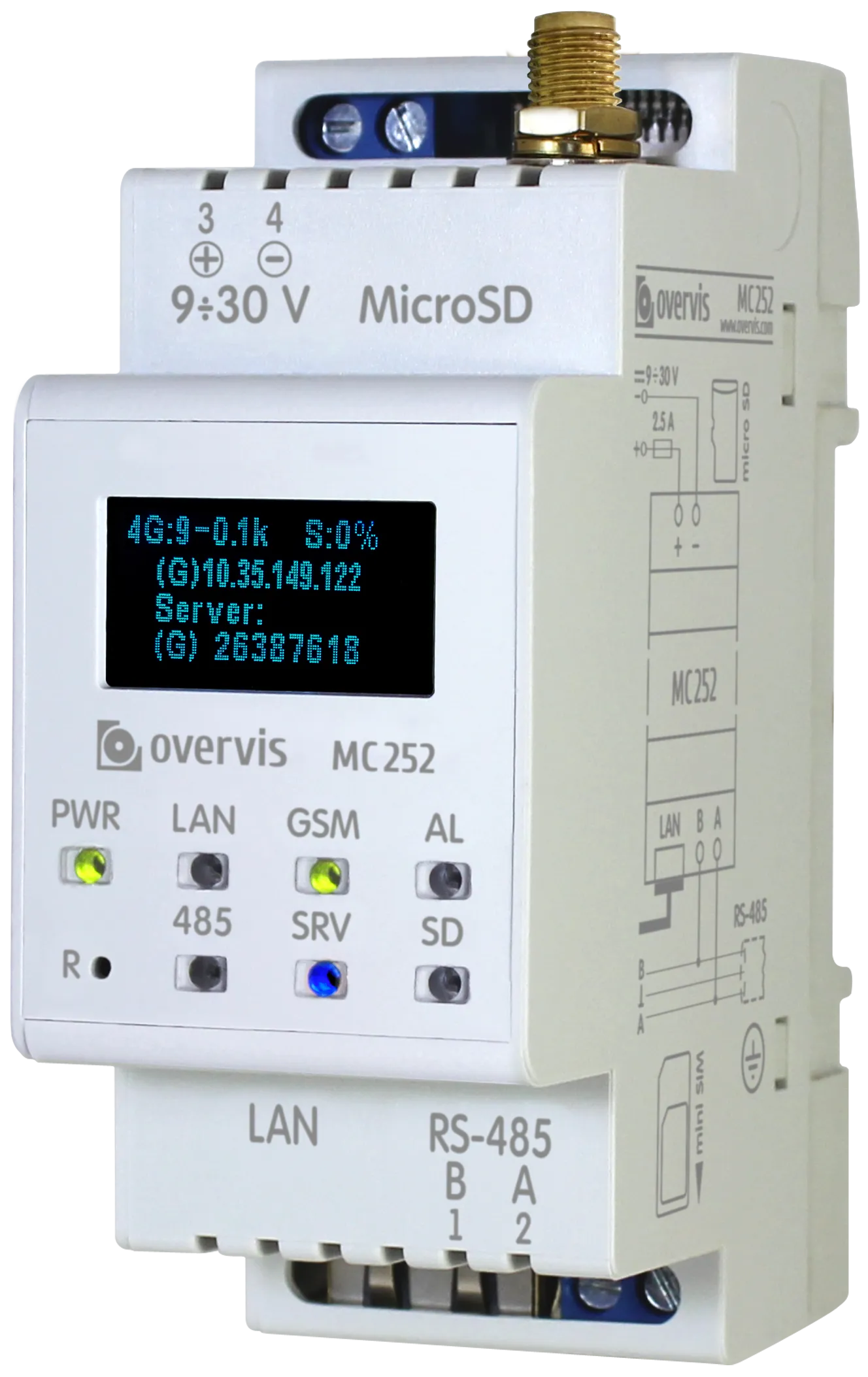


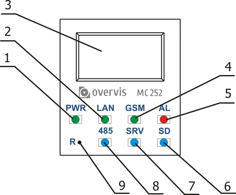
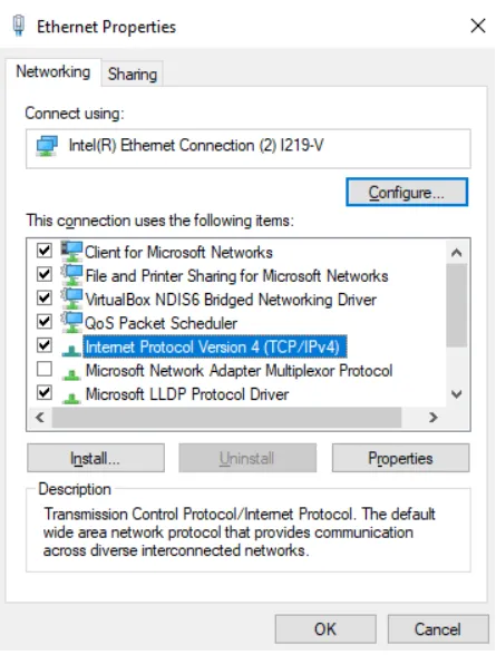
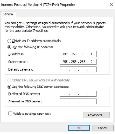
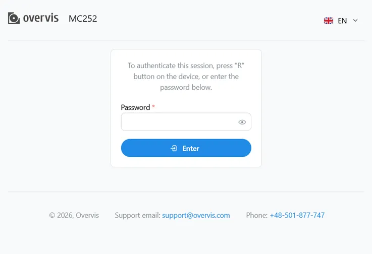 Fig. 1 - The login page
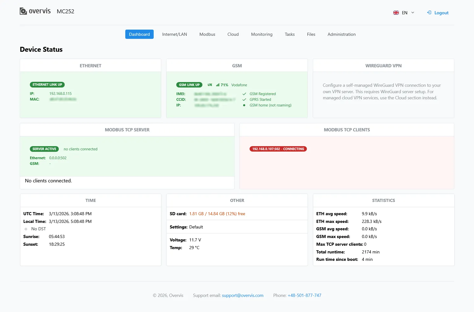 Fig. 2 - The dashboard page
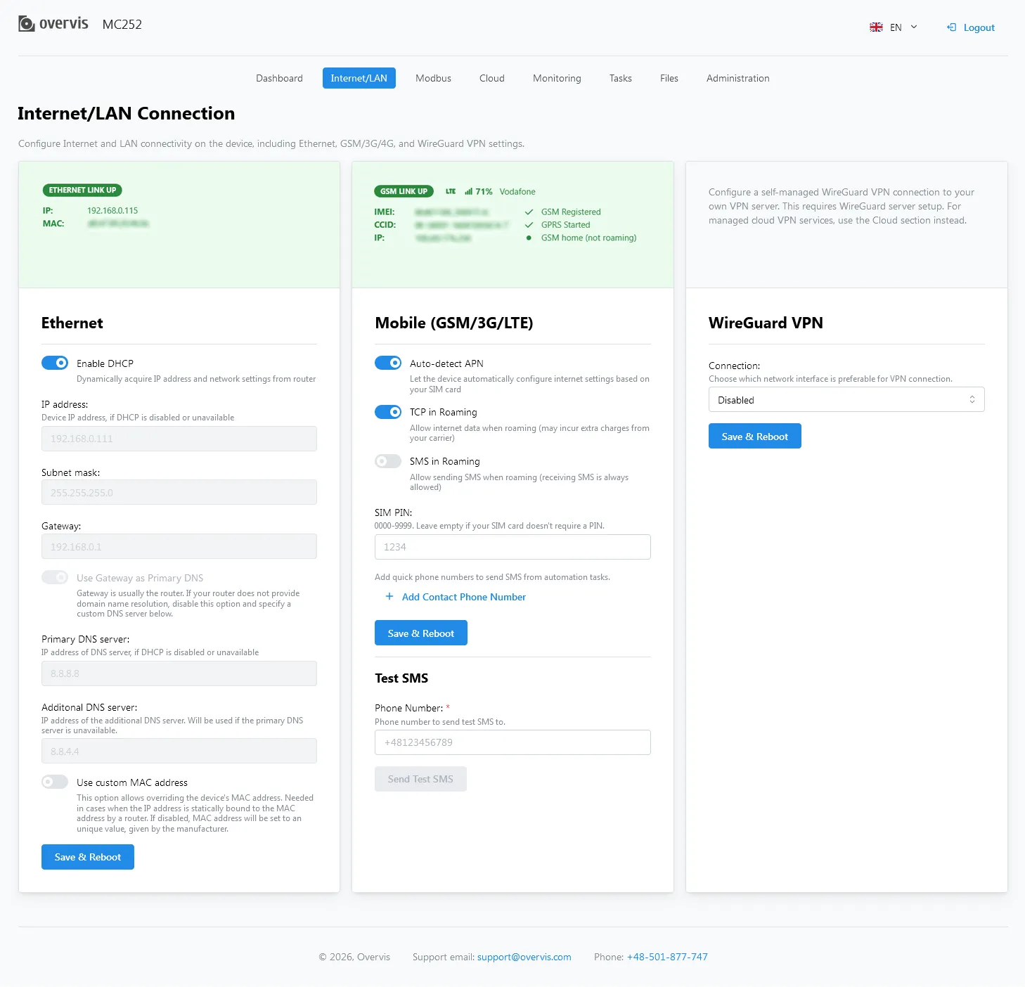 Fig. 3 - The LAN/Internet configuration page
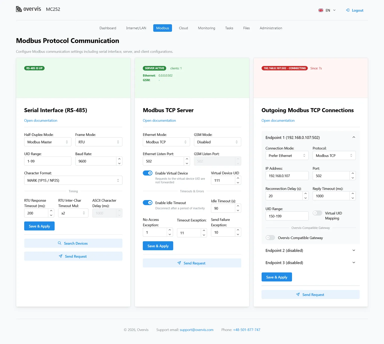 Fig. 4 - The Modbus configuration page
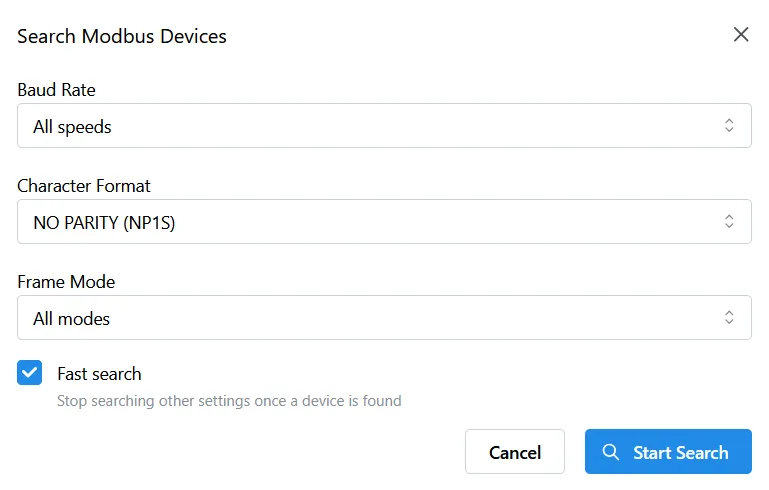 Fig. 5 - The Search Devices tool options
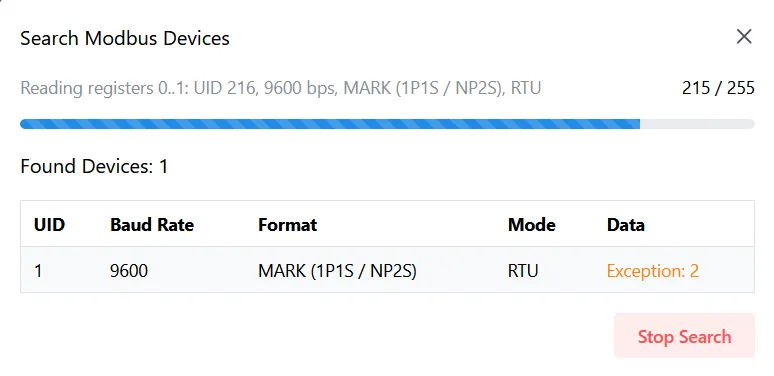 Fig. 6 - The devices search progress
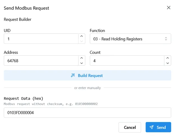 Fig. 7 - The Send Request tool options
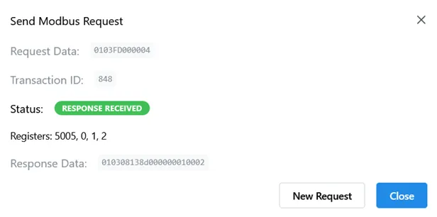 Fig. 8 - The Modbus request results
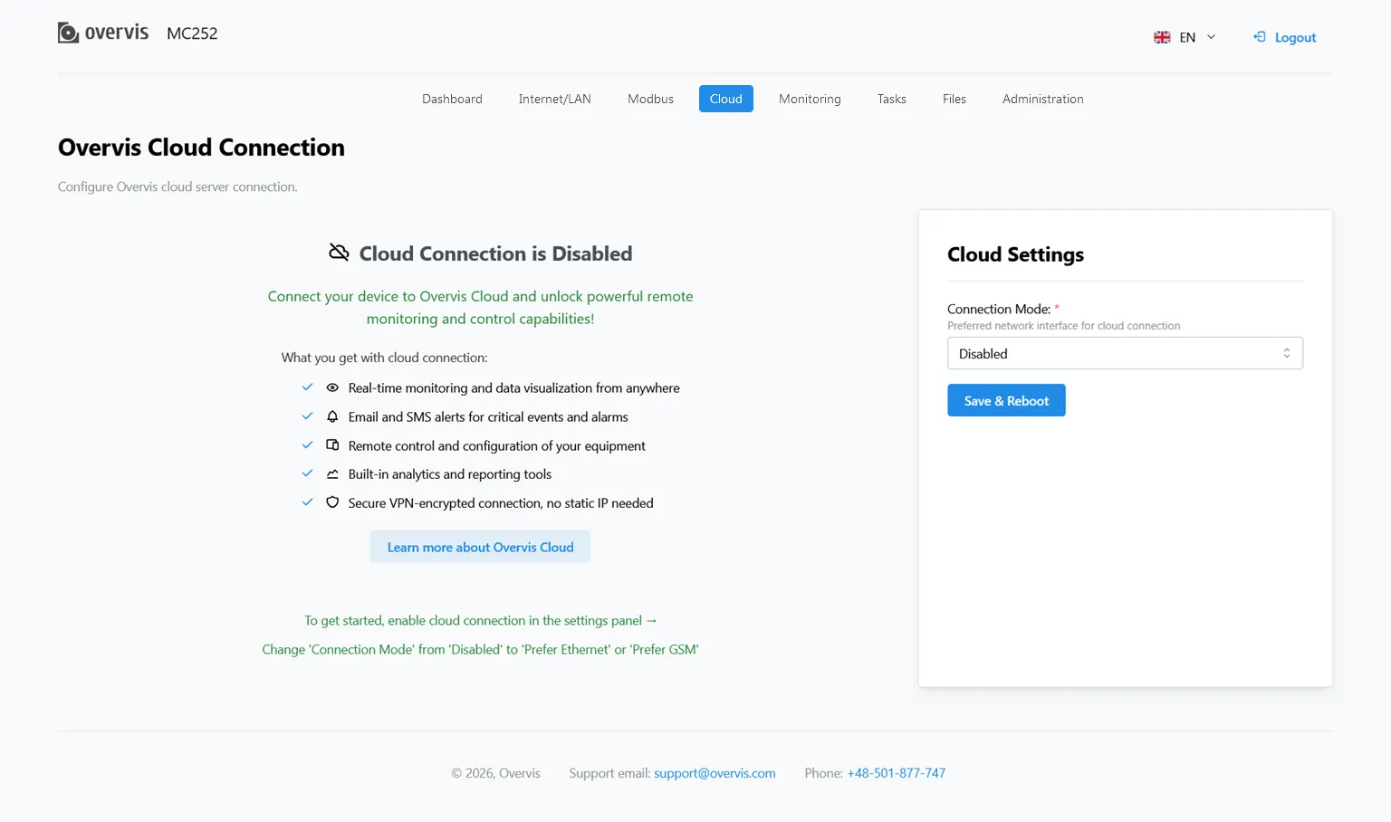 Fig. 9 - The cloud connection configuration page
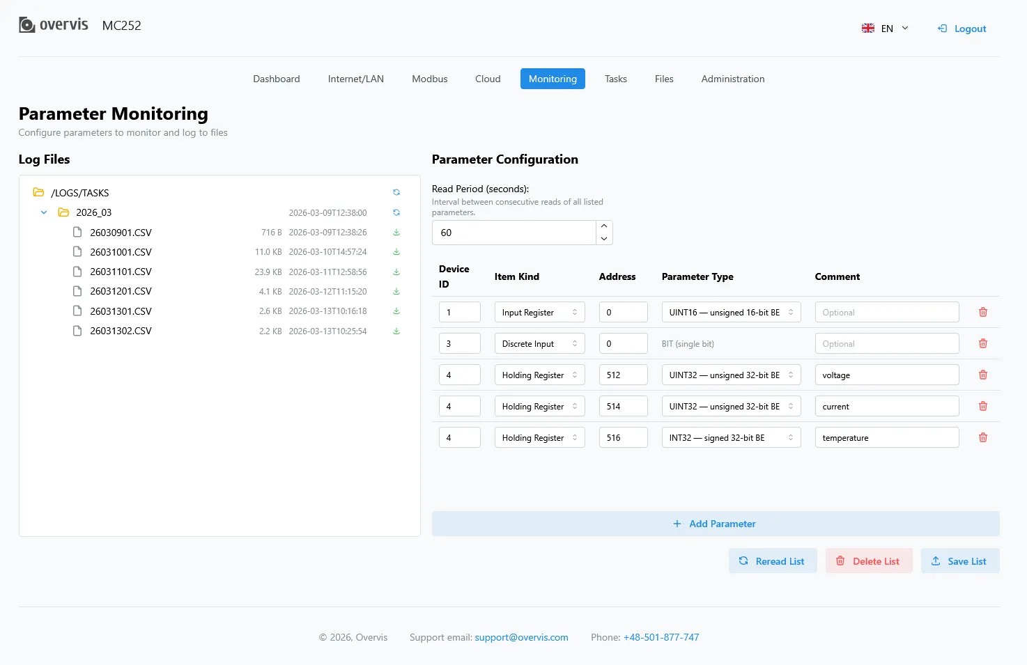 Fig. 10 - The monitoring setup page
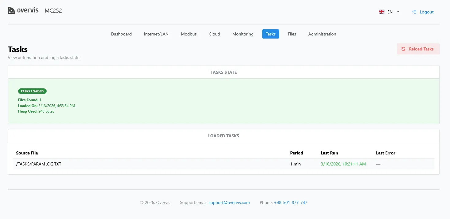 Fig. 11 - The tasks management page
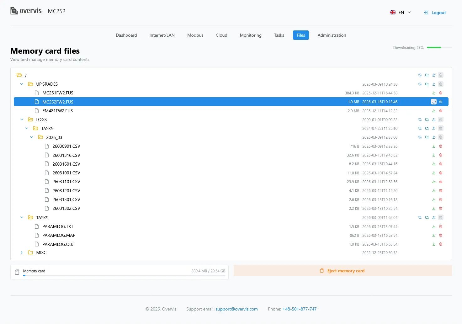 Fig. 12 - The memory card page
 Fig. 13 - The administration page