Novatek-Electro OB-215 Documentation
https://www.overvis.com/docs/uk/ob-215/
2026-07-30
| |
|---|
Novatek-Electro OB-215
OB-215 — це модуль цифрового вводу/виводу виробництва NOVATEK-ELECTRO LTD. Забезпечує універсальні можливості вимірювання та керування через інтерфейс RS-485 з використанням протоколу ModBus. Ключові особливостіSection titled “Ключові особливості”
ДокументаціяSection titled “Документація”
Додаткові ресурсиSection titled “Додаткові ресурси”
ПідтримкаSection titled “Підтримка”
|
| | |||||||||||||||||||||||||||||||||||||||||||||||||||||||||||||||||||||||||||||||||||||||||||||||||||||||||||||||||||||||||||||||||||||||||||||||||||||||||||||||||||||||||||||||||||||||||||||||||||||||||||||||||||||||||||||||||||||||||||||||||||||||||||||||||||||||||||||||||||||||||||||||||||||||||||||||||||||||||||||||||||||||||||||||||||||||||||||||||||||||||||||||||||||||||||||||||||||||||||||||||||||||||||||||||||||||||||||||||||||||||||||||||||||||||||||
|---|---|---|---|---|---|---|---|---|---|---|---|---|---|---|---|---|---|---|---|---|---|---|---|---|---|---|---|---|---|---|---|---|---|---|---|---|---|---|---|---|---|---|---|---|---|---|---|---|---|---|---|---|---|---|---|---|---|---|---|---|---|---|---|---|---|---|---|---|---|---|---|---|---|---|---|---|---|---|---|---|---|---|---|---|---|---|---|---|---|---|---|---|---|---|---|---|---|---|---|---|---|---|---|---|---|---|---|---|---|---|---|---|---|---|---|---|---|---|---|---|---|---|---|---|---|---|---|---|---|---|---|---|---|---|---|---|---|---|---|---|---|---|---|---|---|---|---|---|---|---|---|---|---|---|---|---|---|---|---|---|---|---|---|---|---|---|---|---|---|---|---|---|---|---|---|---|---|---|---|---|---|---|---|---|---|---|---|---|---|---|---|---|---|---|---|---|---|---|---|---|---|---|---|---|---|---|---|---|---|---|---|---|---|---|---|---|---|---|---|---|---|---|---|---|---|---|---|---|---|---|---|---|---|---|---|---|---|---|---|---|---|---|---|---|---|---|---|---|---|---|---|---|---|---|---|---|---|---|---|---|---|---|---|---|---|---|---|---|---|---|---|---|---|---|---|---|---|---|---|---|---|---|---|---|---|---|---|---|---|---|---|---|---|---|---|---|---|---|---|---|---|---|---|---|---|---|---|---|---|---|---|---|---|---|---|---|---|---|---|---|---|---|---|---|---|---|---|---|---|---|---|---|---|---|---|---|---|---|---|---|---|---|---|---|---|---|---|---|---|---|---|---|---|---|---|---|---|---|---|---|---|---|---|---|---|---|---|---|---|---|---|---|---|---|---|---|---|---|---|---|---|---|---|---|---|---|---|---|---|---|---|---|---|---|---|---|---|---|---|---|---|---|---|---|---|---|---|---|---|---|---|---|---|---|---|---|---|---|---|---|---|---|---|---|---|---|---|---|---|---|---|---|---|---|---|---|---|---|---|---|---|---|---|---|---|---|---|---|---|---|---|---|---|---|---|---|---|---|---|---|---|
OB-215 Operating Manual
NOVATEK-ELECTRO LTD Intelligent industrial electronic DIGITAL I/O MODULE OB-215 OPERATING MANUAL Quality control system on the development and production complies with requirements ISO 9001:2015 Dear customer, Company NOVATEK-ELECTRO LTD. thanks you for purchasing our devices. You will be able to use properly the device after carefully studying the Operating Manual. Keep the Operating Manual throughout the service life of the device. UKRAINE, Odesa — www.novatek-electro.com 1 PurposeSection titled “1 Purpose”Digital I/O module OB-215 (hereinafter referred to as the device or OB-215) can be used as the following:
OB-215 provides:
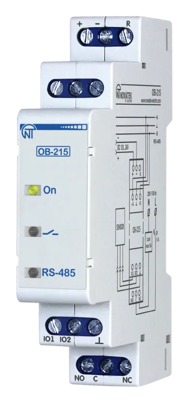
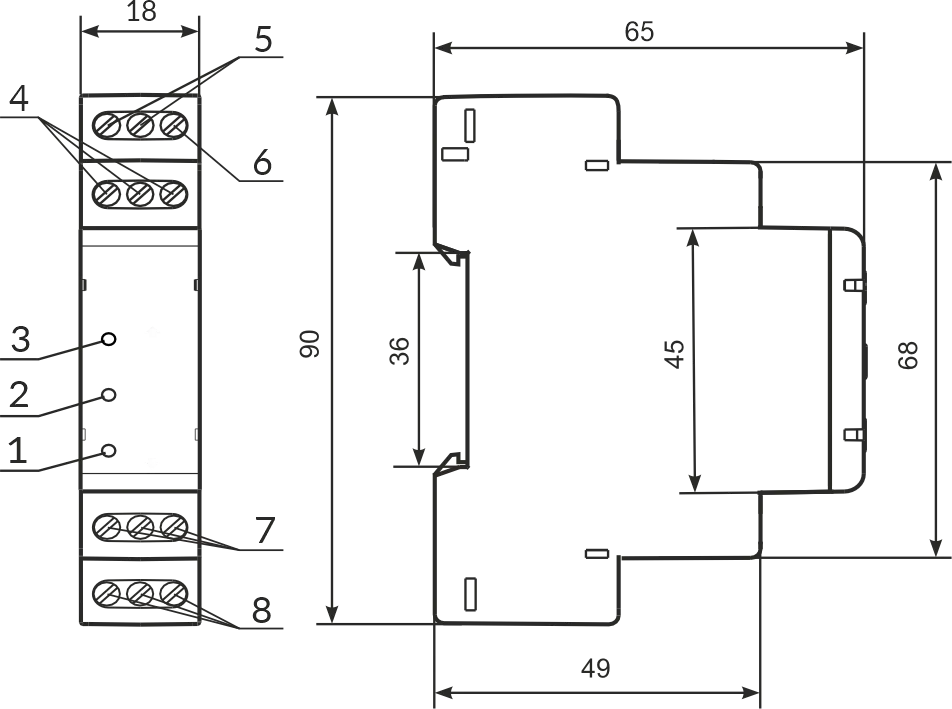
RS-485 interface provides control of the connected devices and reading of the sensors readings via the ModBus protocol. Parameter setting is set by the user from the Control Panel using the ModBus RTU/ASCII protocol or any other program that allows working with the ModBus RTU/ASCII protocol. The status of the relay output, the presence of the power supply and the data exchange are displayed using indicators located on the front panel (Fig. 1, it. 1, 2, 3). The overall dimensions and layout of the device are shown in Fig. 1.
1 – indicator of data exchange via RS-485 interface (it is on when data is being exchanged); 2 – indicator of the status of the relay output (it is on with closed relay contacts); 3 – indicator « ⏻ » is on when there is supply voltage; 4 – terminals for connecting RS-485 communication; 5 – device power supply terminals; 6 – terminal for reloading (resetting) the device; 7 – terminals for connecting sensors; 8 – output terminals of relay contacts (8 А). Figure 1 – OB-215 front panel and overall dimensions 2 Technical SpecificationsSection titled “2 Technical Specifications”Table 1 – Basic Technical Specifications
The device meets the requirements of the following: EN 60947-1; EN 60947-6-2; EN 55011; EN 61000-4-2
SettingsSection titled “Settings”Table 2 – Settings for OB-215
Operation mode values:
Connected digital sensor (Address 101)
Relay control (Address 103)
Relay control values:
Thresholds (Addresses 104–105)
Pulse counter mode (Address 106)
Pulse counter mode values:
Additional settings
RS-485 settings
Rate of exchange values:
Parity check and stop bits values:
UART(TTL)→RS-485 settings
Rate of exchange UART(TTL)→RS-485 values:
Stop bits for UART(TTL)→RS-485 values:
Parity check for UART(TTL)→RS-485 values:
Password protection
Relay control settings
Value conversion settings
Notes:
Output Contact SpecificationsSection titled “Output Contact Specifications”Table 3 – Output Contact Specifications
3 Operating ConditionsSection titled “3 Operating Conditions”The product is intended for operation in the following conditions:
If the temperature of the product after transportation or storage differs from the ambient temperature at which it is supposed to be operated, then before connecting to the mains keep the product under the operating conditions within two hours (because of condensation may be on the product elements). 4 Device ConnectionSection titled “4 Device Connection”It is not allowed to leave exposed portions of wire protruding beyond the terminal block. Error when performing the installation works may damage the device and connected devices.
For a reliable contact, tighten the terminal screws with the force indicated in Table 1. When reducing the tightening torque, the junction point is heated, the terminal block may be melted and wire can burn. If you increase the tightening torque, it is possible to have thread failure of the terminal block screws or the compression of the connected wire.
To connect the device to the ModBus network, use CAT.1 or higher twisted pair cable.
5 Using the DeviceSection titled “5 Using the Device”After the power is on, the indicator « ⏻ » lights up. The indicator flashes for 1.5 seconds. Then the indicators and «RS-485» light up (Fig. 1, pos. 1, 2, 3) and after 0.5 second they go out. To change any parameters you need:
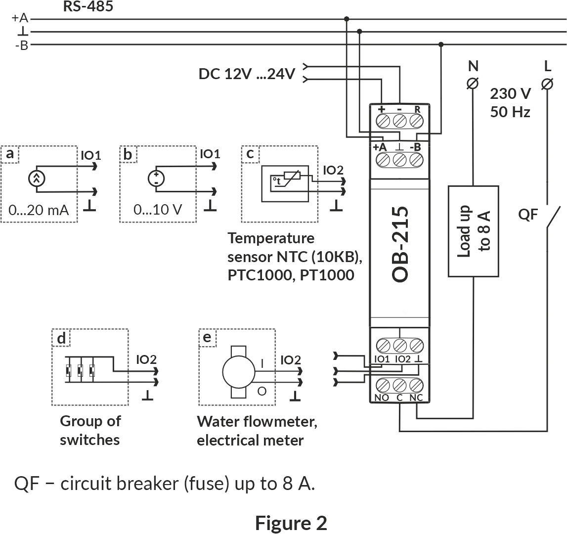
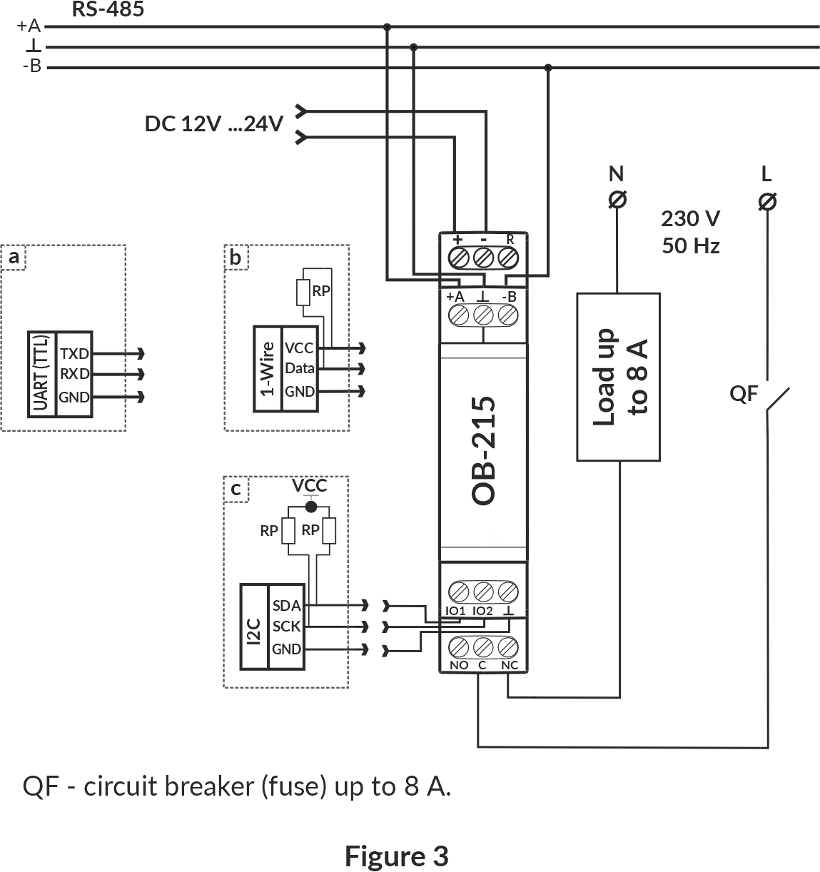
During the data exchange, the “RS-485” indicator flashes, otherwise the “RS-485” indicator does not light up. Operation ModesSection titled “Operation Modes”Measurement ModeSection titled “Measurement Mode”In this mode, the device measures the readings of sensors connected to the inputs “IO1” or “IO2” (Fig. 1, it. 7), and depending on the settings, performs the necessary actions. Interface Transformation ModeSection titled “Interface Transformation Mode”In this mode, the device converts the data received via the RS-485 interface (Modbus RTU/ASCII) to the UART (TTL) interface (Table 2, address 100, value “7”). More detailed description see in Transformation of UART (TTL) interfaces to RS-485. Device OperationSection titled “Device Operation”Pulse CounterSection titled “Pulse Counter”Connect the external device as shown in Fig. 2 (e). Set up the device for operation in the Pulse Counter Mode (Table 2, address 100, value “0”). In this mode, the device counts the number of pulses at the input “IO2” (of duration no less than the value indicated in Table 2, Address 107, value in ms) and stores the data in memory with a periodicity of 1 minute. If the device has been turned off before 1 minute has ended, the last stored value will be restored upon power-up. If you change the value in the register (Address 108), all the stored values of the pulse meter will be deleted. When the value specified in the register (address 108) is reached, the counter is incremented by one (Table 6, address 4:5). To set the initial value of the pulse counter it is necessary to write-down the required value into the register (Table 6, address 4:5). Logic Input/Pulse RelaySection titled “Logic Input/Pulse Relay”When selecting Logic Input/Pulse Relay mode (Table 2, Address 100, Value 1), or changing the Pulse meter mode (Table 2, Address 106), if the relay contacts were closed “C – NO” (LED lights up), the device will automatically open the “C-NO” contacts (LED turns off). Logic Input Mode Connect the device according to Fig. 2 (d). Set up the device for operation in the Logic Input/Pulse Relay Mode (Table 2, address 100, value “1”), set the required pulse count mode (Table 2, address 106, value “2”). If the logic state on the “IO2” terminal (Fig. 1, it. 6) changes to a high level (rising edge), the device opens the contacts of the “C - NO” relay and closes the contacts of the “C - NC” relay (Fig. 1, it. 7). If the logic state on the “IO2” terminal (Fig. 1, it. 6) changes to a low level (falling edge), the device will open the contacts of the “C - NC” relay and close the “C - NO” contacts (Fig. 1, it. 7). Pulse Relay Mode Connect the device according to Fig. 2 (d). Set up the device for operation in the Logic Input/Pulse Relay Mode (Table 2, address 100, value “1”), set Pulse Counter Mode (Table 2, address 106, value “0” or value “1”). For short-time pulse with duration of at least the value specified in Table 2 (Address 107, the value in ms) at the «IO2» terminal (Fig. 1, it. 6), the device closes the contacts of the “C - NO” relay and opens the contacts of the “C - NC” relay. If the pulse is repeated for a short time, the device will open the contacts of the “C - NO” relay and close the “C - NC” relay contacts. Voltage MeasurementSection titled “Voltage Measurement”Connect the device according to Fig. 2 (b). Set up the device for operation in the Voltage measurement mode (Table 2, address 100, value “2”). If it is necessary that the device monitors the threshold voltage, it is required to write a value other than “0” in the “Relay control” register (Table 2, address 103). If required, set the operation thresholds (Table 2, address 104 – upper threshold, address 105 – lower threshold). In this mode, the device measures the DC voltage. The measured voltage value can be read at address 6 (Table 6). Voltage values are derived to one hundredth of a volt (1234 = 12.34 V; 123 = 1.23 V). Current MeasurementSection titled “Current Measurement”Connect the device according to Fig. 2 (a). Set up the device for operation in the “Current measurement” mode (Table 2, address 100, value “3”). If it is necessary for the device monitors the threshold current, it is required to write a value other than “0” in the “Relay control” register (Table 2, address 103). If required, set the operation thresholds (Table 2, address 104 – upper threshold, address 105 – lower threshold). In this mode, the device measures DC. The measured current value can be read at address 6 (Table 6). Current values are derived to one hundredth of a milliampere (1234 = 12.34 mА; 123 = 1.23 mА). Temperature MeasurementSection titled “Temperature Measurement”Connect the device according to Fig. 2 (c). Set up the device for operation in the Temperature measurement mode (Table 2, address 100, value “4”, “5”, “6”). If it is necessary for the device monitors the threshold temperature value, it is required to write a value other than “0” in the register “Relay control” (Table 2, address 103). For set the operation thresholds to write a value in address 104 - upper threshold and address 105 - lower threshold (Table 2). If it is required to correct the temperature, it is necessary to record the correction factor in the “Temperature Correction” register (Table 2, Address 102). In this mode, the device measures the temperature with the help of thermistor. Temperature values are derived to one tenth of a Celsius degree (1234 = 123.4 °С; 123 = 12.3 °С). Connection of Digital SensorsSection titled “Connection of Digital Sensors”The device supports the digital sensors listed in Table 2 (address 101). The measured value of the digital sensors can be read at the addresses 11–15, Table 6 (depending on what value the sensor measures). The query time period of digital sensors is 3 s. In case if it is required to correct the temperature measured by the digital sensor, it is necessary to enter the temperature correction factor in register 102 (Table 2). If a value other than zero is set in the register 103 (Table 2), the relay will be controlled based on the measured values in register 11 (Table 6). Temperature values are derived to one tenth of a Celsius degree (1234 = 123.4 °С; 123 = 12.3 °С). When connecting sensors via the I2C interface, refer to the specific sensor’s passport. Converting RS-485 Interface to UART (TTL)Section titled “Converting RS-485 Interface to UART (TTL)”Connect the device according to Fig. 3 (a). Set up the device for operation in RS-485-UART (TTL) mode (Table 2, address 100, value “7”). In this mode, the device receives (transmits) data via the RS-485 ModBus RTU/ASCII interface (Fig. 1, it. 4) and converts them to the UART interface. Example of query and response is shown in Fig. 10 and Fig. 11. Conversion of the Measured Voltage (Current) ValueSection titled “Conversion of the Measured Voltage (Current) Value”To convert the measured voltage (current) to another value, it is necessary to enable the conversion (Table 2, address 130, value 1) and adjust the conversion ranges. For example, the measured voltage should be converted to bars with such sensor parameters: voltage range from 0.5 V to 8 V corresponds to a pressure of 1 bar to 25 bar. Conversion Ranges Adjustment: minimum input value (address 131, value of 50 corresponds to 0.5 V), maximum input value (address 132, value of 800 corresponds to 8 V), minimum converted value (address 133, value of 1 corresponds to 1 bar), maximum converted value (address 134, value of 25 corresponds to 25 bars). Converted value will be displayed in the register (Table 6, address 16). Restarting the Device and Reset to Factory SettingsSection titled “Restarting the Device and Reset to Factory Settings”If the device needs to be restarted, the “R” and ”–” terminals (Fig. 1) must be closed and held for 3 seconds. If you want to restore the factory settings of the device, you must close and hold the “R” and ”–” terminals (Fig. 1) for more than 10 seconds. After 10 seconds, the device automatically restores the factory settings and reloads. Operation with RS (EIA/TIA)-485 Interface via ModBus ProtocolSection titled “Operation with RS (EIA/TIA)-485 Interface via ModBus Protocol”OB-215 allows data exchanging with external devices via the serial interface of RS (EIA/TIA)-485 via ModBus protocol with the limited set of commands (see Table 4 for a list of supported functions). When constructing a network, the principle of the master-slave organization is used where OB-215 acts as the slave. There can be only one master node and several slave nodes in the network. As the master node is a personal computer or a programmable logic controller. With this organization, the initiator of the exchange cycles can only be the master node. The queries of the master node are individual (addressed to a particular device). OB-215 performs transmission, responding to individual queries of the master node. If errors are found in receiving queries, or if the received command cannot be executed, OB-215 as the respond generates an error message. Addresses (in decimal form) of command registers and their purpose are given in Table 5. Addresses (in decimal form) of additional registers and their purpose are given in Table 6. Supported FunctionsSection titled “Supported Functions”Table 4 – List of supported functions
Command RegisterSection titled “Command Register”Table 5 – Command Register
Command codes:
Notes:
Additional RegistersSection titled “Additional Registers”Table 6 – Additional registers
Digital sensors
Converting
Notes:
Status RegisterSection titled “Status Register”Table 6 (continued) – Status Register (Address 2:3)
Message FormatsSection titled “Message Formats”The exchange protocol has clearly defined message formats. Compliance with the formats ensures the correctness and stability of the network. Byte FormatSection titled “Byte Format”OB-215 is configured to operate with one of two formats of data bytes: with parity control (Fig. 4) and without parity control (Fig. 5). In parity control mode, the type of control is also indicated: Even or Odd. Transmission of data bits is performed by the least significant bits forward. By default (during manufacture) the device is configured to operate without parity control and with two stop bits. Byte transfer is performed at speeds of 1200, 2400, 4800, 9600, 14400 and 19200 bps. By default, during manufacturing, the device is configured to operate at a speed of 9600 bps.
Figure 4, 5 – Byte format with parity control (top) and without parity control (bottom) Frame FormatSection titled “Frame Format”The frame length cannot exceed 256 bytes for ModBus RTU and 513 bytes for ModBus ASCII. In ModBus RTU mode the start and end of the frame are monitored by silence intervals of at least 3.5 bytes. The frame must be transmitted as a continuous byte stream. The correctness of frame acceptance is additionally controlled by checking the CRC checksum. The address field occupies one byte. The addresses of the slaves are in the range from 1 to 247. Fig. 6 shows the RTU frame format.
Figure 6 – RTU frame format In ModBus ASCII mode the start and end of the frame are controlled by special characters (symbols (’:’ 0x3A) – for start of the frame; symbols (‘CRLF’ 0x0D0x0A) – for the end of the frame). The frame must be transmitted as a continuous stream of bytes. The correctness of frame acceptance is additionally controlled by checking the LRC checksum. The address field occupies two bytes. The addresses of the slaves are in the range from 1 to 247. Fig. 7 shows the ASCII frame format.
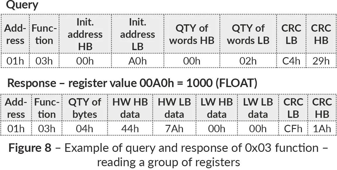
Figure 7 – ASCII frame format Generation and Verification of ChecksumSection titled “Generation and Verification of Checksum”The sending device generates a checksum for all bytes of the transmitted message. OB-215 similarly generates a checksum for all bytes of the received message and compares it with the checksum received from the transmitter. If there is a mismatch between the generated checksum and the received checksum, an error message is generated. CRC Checksum GenerationSection titled “CRC Checksum Generation”The checksum in the message is sent by the least significant byte forward, it is a cyclic verification code based on the irreducible polynomial 0xA001. Subroutine for CRC checksum generation in C language: LRC Checksum GenerationSection titled “LRC Checksum Generation”The checksum in the message is transmitted by the most significant byte forward, which is a longitudinal redundancy check. Subroutine for LRC checksum generation in C language: Command SystemSection titled “Command System”Function 0x03 – Reading a Group of RegistersSection titled “Function 0x03 – Reading a Group of Registers”Function 0x03 provides reading of the contents of registers OB-215. The master query contains the address of the initial register, as well as the number of words to read. OB-215 response contains the number of bytes to return and the requested data. The number of registers returned is limited to 50. If the number of registers in the query exceeds 50 (100 bytes), the response is not divided into frames. An example of the query and response in ModBus RTU is shown in Fig. 8.
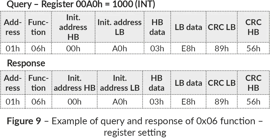
Figure 8 – Example of reading registers (Function 0x03) Function 0x06 – Recording the RegisterSection titled “Function 0x06 – Recording the Register”The function 0x06 provides recording in one OB-215 register. The master query contains the address of the register and the data to be written. The device response is the same as the master query and contains the register address and the set data. An example of the query and response in ModBus RTU mode is shown in Fig. 9.
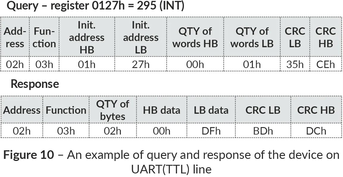
Figure 9 – Example of writing to a register (Function 0x06) Transformation of UART (TTL) Interfaces to RS-485Section titled “Transformation of UART (TTL) Interfaces to RS-485”In the interface transformation mode, if the query was not addressed to OB-215, it will be redirected to the device connected to «IO1» and «IO2». In this case the indicator «RS-485» will not change its state. An example of query and response to the device on UART (TTL) line is shown in Fig. 10.
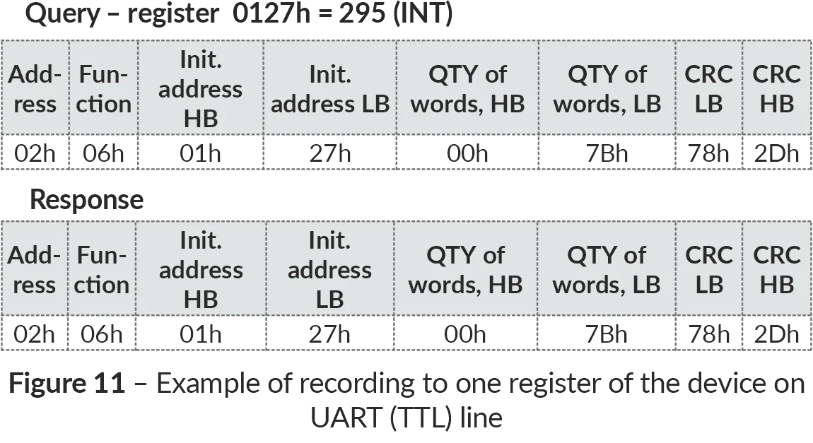
Figure 10 – Example of query and response to the device on UART (TTL) line An example of recording to one register of the device on UART (TTL) line is shown in Fig. 11.
Figure 11 – Example of recording to one register of the device on UART (TTL) line ModBus Error CodesSection titled “ModBus Error Codes”
6 Safety PrecautionsSection titled “6 Safety Precautions”It is not allowed water penetration on terminals and internal elements of the device. During operation and maintenance the regulatory document requirements must be met, namely:
7 Maintenance ProcedureSection titled “7 Maintenance Procedure”Recommended frequency of maintenance is every six months. Maintenance Procedure:
Do not use abrasives and solvents for cleaning. 8 Transportation and StorageSection titled “8 Transportation and Storage”The device in the original package is permitted to be transported and stored at the temperature from minus 45 to +60 °C and relative humidity of no more than 80 %, not in aggressive environment. 9 Service Life and WarrantySection titled “9 Service Life and Warranty”The lifetime of the device is 10 years. Shelf life is 3 years. Warranty period of the device operation is 5 years from the date of sale. During the warranty period of operation, the manufacturer performs free repair of the device, if the user has complied with the requirements of the Operating Manual. Warranty service is performed at the place of purchase or by the manufacturer of the device. Post-warranty service of the device is performed by the manufacturer at current rates. Before sending for repair, the device should be packed in the original or other packing excluding mechanical damage. For all questions, please contact the manufacturer: “Novatek-Electro” Ltd. 59, Mykhailo Boltenko (Admiral Lazarev) str., Odesa, Ukraine, 65007 Tel: +38 (067) 565 37 68 +38 (050) 359 39 11 +38 (063) 301 30 40 VN241024 |