Novatek-Electro EM-486 Documentation
https://www.overvis.com/docs/en/em-486/
2026-07-30
| |
|---|
Novatek-Electro EM-486
The EM-486 is a MODBUS RTU/ASCII (RS-485) protocol converter manufactured by NOVATEK-ELECTRO LTD. EM-486 provides data collection from connected devices (analog sensors and MODBUS devices), data transfer to the server, access to data (via MODBUS TCP protocol or SMS text messages), event tracking and response (relay control, SMS sending - notifications, writing values to MODBUS devices, saving read values to the log). Key FeaturesSection titled “Key Features”
Common Use CasesSection titled “Common Use Cases”
DocumentationSection titled “Documentation”
Technical ReferenceSection titled “Technical Reference”
ExamplesSection titled “Examples”
ResourcesSection titled “Resources”
SupportSection titled “Support”
|
| | ||||||||||||||||||||||||||||||||||||||||||||||||||||||||||||||||||||||||||||||||||||||||||||||||||||||||||||||||||||||||||||||||||||||||||||||||||||||||||||||||||||||||||||||||||||||||||||||||||||||||||||||||||||||||||||||||||||
|---|---|---|---|---|---|---|---|---|---|---|---|---|---|---|---|---|---|---|---|---|---|---|---|---|---|---|---|---|---|---|---|---|---|---|---|---|---|---|---|---|---|---|---|---|---|---|---|---|---|---|---|---|---|---|---|---|---|---|---|---|---|---|---|---|---|---|---|---|---|---|---|---|---|---|---|---|---|---|---|---|---|---|---|---|---|---|---|---|---|---|---|---|---|---|---|---|---|---|---|---|---|---|---|---|---|---|---|---|---|---|---|---|---|---|---|---|---|---|---|---|---|---|---|---|---|---|---|---|---|---|---|---|---|---|---|---|---|---|---|---|---|---|---|---|---|---|---|---|---|---|---|---|---|---|---|---|---|---|---|---|---|---|---|---|---|---|---|---|---|---|---|---|---|---|---|---|---|---|---|---|---|---|---|---|---|---|---|---|---|---|---|---|---|---|---|---|---|---|---|---|---|---|---|---|---|---|---|---|---|---|---|---|---|---|---|---|---|---|---|---|---|---|---|---|---|---|---|---|
EM-486 Operating Manual
The EM-486 is a MODBUS RTU/ASCII (RS-485) protocol converter manufactured by NOVATEK-ELECTRO LTD. During operation and maintenance, the regulatory document requirements must be met, namely: Regulations for Operation of Consumer Electrical Installations; Safety Rules for Operation of Consumer Electrical Installations; Occupational Safety when in Operation of Electrical Installations. Installation, adjustment and maintenance of the device must be performed by qualified personnel having studied this Operating Manual. In compliance with the requirements of this Operating Manual and regulations the device is safe for use. This Operating Manual is intended to familiarize you with the device, the requirements for safety, operation and maintenance procedures of the MODBUS RTU/ASCII (RS-485) protocol converter EM-486 (hereinafter referred to as EM-486, device). The device meets the requirements: EN 60947-1; EN 60947-6-2; EN 55011; EN 61000-4-2. Harmful substances in amounts exceeding maximum permissible concentrations are not available. Versions of this device are listed in Appendix A - Versions and Modifications. Terms and AbbreviationsSection titled “Terms and Abbreviations”
1 PurposeSection titled “1 Purpose”1.1 Purpose of the DeviceSection titled “1.1 Purpose of the Device”EM-486 provides data collection from connected devices (analog sensors and MODBUS devices), data transfer to the server, access to data (via MODBUS TCP protocol or SMS text messages), event tracking and response (relay control, SMS sending - notifications, writing values to MODBUS devices, saving read values to the log). EM-486 has:
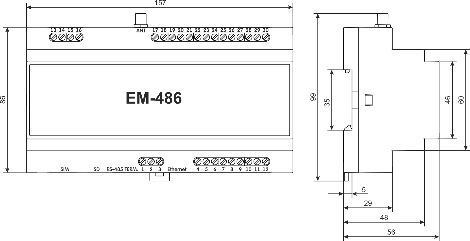
1.2 Overall and Setting DimensionsSection titled “1.2 Overall and Setting Dimensions”
Figure 1.1 – Overall dimensions of the device
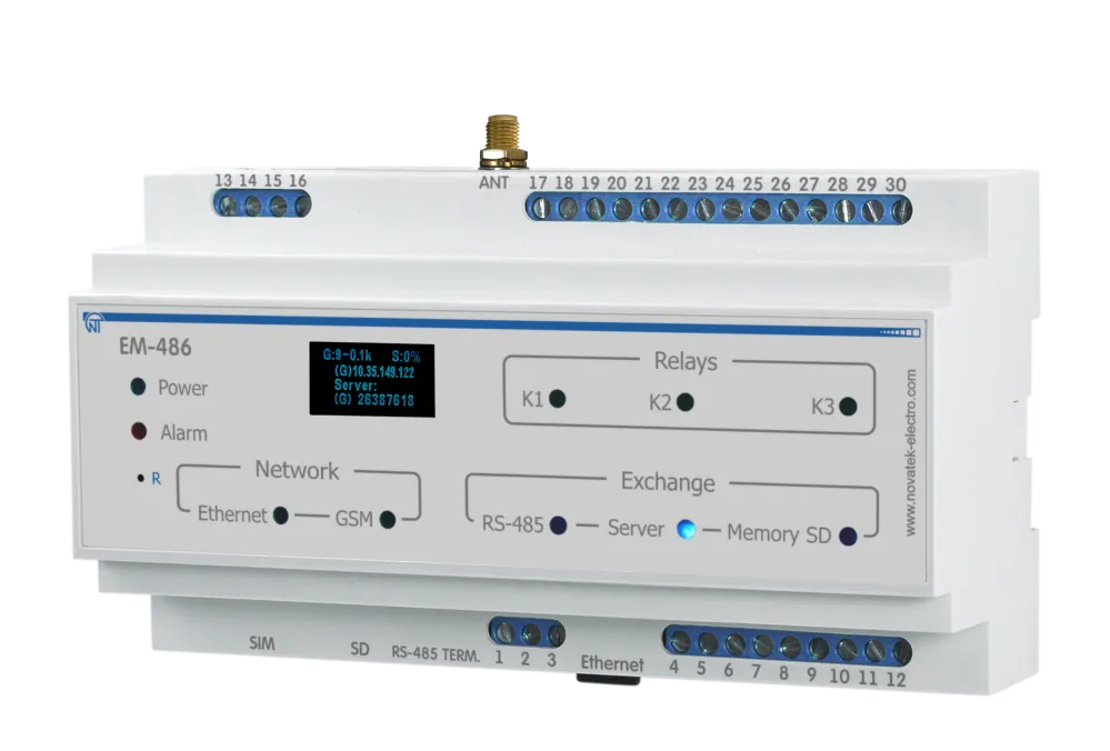
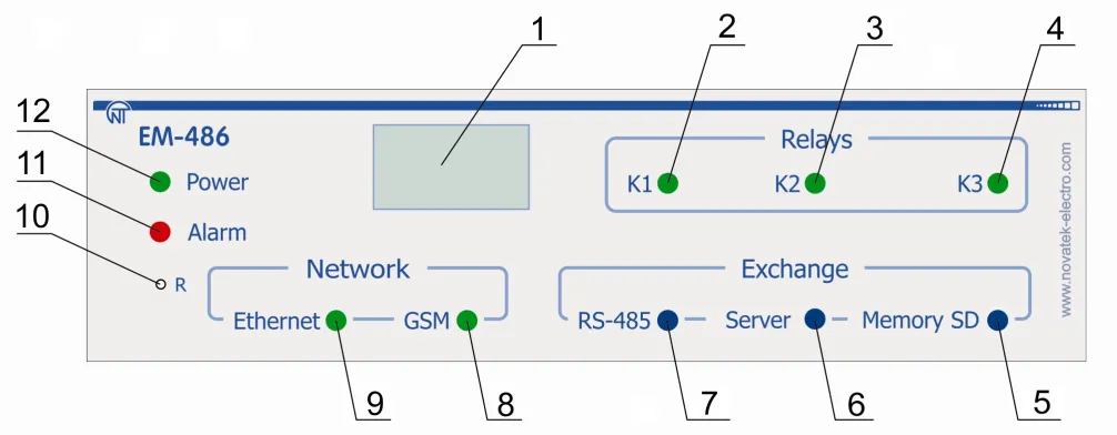
Figure 1.2 – Front panel of EM-486
1.3 Operating ConditionsSection titled “1.3 Operating Conditions”EM-486 is designed for operation in the following conditions:
If the temperature of the device after transportation or storage is different from the temperature of the environment in which its operation is assumed, then before connecting to the mains keep the device in operation conditions for two hours (because on the device elements condensation may be available). 2 Complete Supply SetSection titled “2 Complete Supply Set”
* other types of antennas are delivered in coordination with the buyer 3 Technical SpecificationsSection titled “3 Technical Specifications”
* Connections on the Ethernet networks/Internet can take more time The device remains operational capability in any position in space. 4 DesignSection titled “4 Design”EM-486 provides control for MODBUS in RS-485 network via Ethernet interfaces or GPRS, or via the SMS. The device also allows to read data from devices by MODBUS or from connected sensors. The processor supports connection to the accumulating data cloud server via Ethernet network with a help of microchip of physical interface of Ethernet (or via GPRS with a help of inbuilt GSM-modem, if connection via Ethernet is not available). In addition, EM-486 can be connected via MODBUS TCP Protocol to exchange data with MODBUS devices, or with the device. The controller receives and processes SMS with a password and command read/write for MODBUS devices. When inserting a memory card, the device reads the internal memory for operational logic – program for data collection and tracking of events. The program runs in the background mode. The collected data can be saved to a memory card in tabular or binary files. The device stores in the built-in memory network settings, input and output parameters, security parameters, and action logic. 5 The Intended UseSection titled “5 The Intended Use”5.1 Preparation for OperationSection titled “5.1 Preparation for Operation”5.1.1 Preparation for ConnectionSection titled “5.1.1 Preparation for Connection”
5.1.2 General InstructionsSection titled “5.1.2 General Instructions”To ensure the reliability of electrical connections you should use flexible (stranded) wires with insulation for voltage of not less than 450 V, the ends of which it is necessary to be stripped of insulation for 5±0.5 mm and tightened with bootlaces. Recommended cable cross section for connection is not less 1 mm². EM-486 connection to RS-485 bus is made by cable of twisted pair type Cat.1 or higher category. It is recommended to use the shielded cable, in this case it should be grounded (in accordance with «ANSI/TIA/EIA-485-A-1998» recommendations).
Figure 5.1 – The Device connection diagram
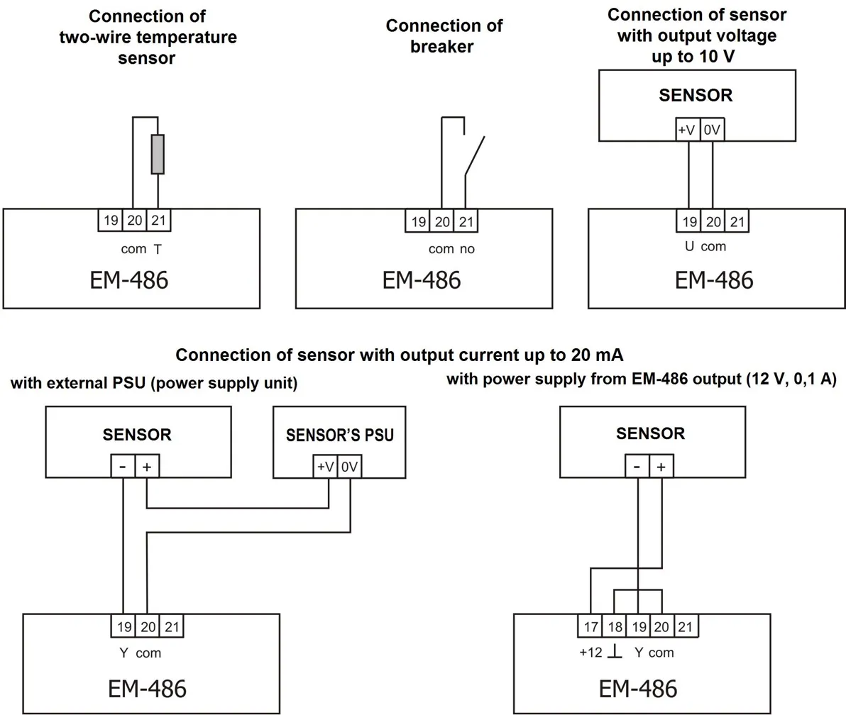
Figure 5.2 – Sensors connection diagram In case of connection to Ethernet it is necessary to use a cable in a set, or the “twisted pair cable” cable of the Cat.5e category with the 8P8C (RJ-45) tip. Wires fastening should exclude mechanical damage, twisting and insulation abrasion of wires. For reliable contact it is necessary to perform tightening of screws of removable terminal block with the force specified in Table 3.1. When reducing the tightening torque, the junction point is heated, terminal block may be melted and wire can burn. If you increase the tightening torque, it is possible to have thread failure of terminal block screws or the compression of the connected wires. To improve operational properties of the device it is recommended to install the F1-F3 fuse (fuse element), or the equivalent in power supply circuit for EM-486 (see Fig 5.1). 5.1.3 EM-486 Switching OnSection titled “5.1.3 EM-486 Switching On”
Table 5.1 – Resistance of integrated terminator of bus RS-485
* – is recommended for cable Cat. 3
5.2 Use of the EM-486Section titled “5.2 Use of the EM-486”5.2.1 General InformationSection titled “5.2.1 General Information”After power supply is provided to the device, all indicators light up, except for «Ethernet» and «GSM», and the device performs the initialization. After this for 2 seconds the indicators, except for indicator of power, light down, and the device proceeds to start the interface of networks connection. At that the display shows general information about the device. Figure 5.3 – Showing the general information about the device on the display The start up can take up to 15 seconds, depending on the settings and quality of connection. Afterwards the device proceeds with performing the user set program of inquiry for sensors and MODBUS devices. The device provides and supports the connection to Ethernet/GSM networks.
The display shows the load of the I/O interfaces, the GSM signal strength and the IP address used: Figure 5.4 – Showing the state of connections on the display
5.2.2 Modes of OperationSection titled “5.2.2 Modes of Operation”5.2.2.1 Connection to ServerSection titled “5.2.2.1 Connection to Server”EM-486 provides and supports connection to the server specified in the device settings. The light up indicator Server means that the connection to server was successfully made. The blinking indicator Server means that there is a data exchange with the server. The data interchange with server is made via one of two protocols: modified MODBUS TCP and MODBUS TCP for reverse connection. 5.2.2.2 Monitoring of Sensors and Devices Connected via RS-485Section titled “5.2.2.2 Monitoring of Sensors and Devices Connected via RS-485”Controller inquires the registers of MODBUS devices, which are connected via RS-485 on requests from the server. EM-486 measures the reading of connected sensors. The taken readings can be resulted in appropriate scale (according the type of sensor and the settings of the device). The resulted values are shown on the display in the appropriate view: Figure 5.5 – Showing the state of inputs on the display (sensors 1 and 2 are disconnected, a sensor of temperature 3 – 25°C, a sensor of current 4 – 0.02 А) The server requests can contain MODBUS EM-486 registers for reading sensor readings, load relay status, current time, etc. 5.2.2.3 Access to MODBUS Network via MODBUS TCP InterfaceSection titled “5.2.2.3 Access to MODBUS Network via MODBUS TCP Interface”EM-486 performs the function of MODBUS gateway and waits for network connection via MODBUS TCP protocol to port 502. The MODBUS TCP connection port can be changed by the user. Connection to PC can be made by any programs – MODBUS TCP clients. The client version for Windows software is available for download on the manufacturer’s web-site (http://novatek-electro.com/en/software.html). At inquiry for client connection to MODBUS TCP port, the device checks a list of available connections. If all connections are already engaged, the connection is cancelled otherwise the device adds it into its internal list of service clients (not more than specified number of clients). At connection with a client the device waits for MODBUS-inquiry from the client. In RS-485 slave mode, RS-485 queries are also received from the MODBUS master. After receiving the inquiry from the client, the device analyses the inquiry and, depending on code of inquired function and actual rights of the client, processes and blocks it. At blocking the inquiry EM-486 can generate and send to the client the specified by the user code of MODBUS exception (by default – code 1). The client’s authority level is defined by the entered passwords. If the inquiry is addressed to EM-486, the device does not re-direct it, but processes it and send the reply to the client. In RS-485 master mode, the inquiries to the other devices are re-directed in MODBUS network, and the reply is waited from the device in MODBUS network – at that event the indicator RS-485 lights on. If the data is received or if the time is out the indicator RS-485 lights down. In redirection mode to a remote server, if communication with remote MODBUS TCP server is set in Ethernet network or GSM, the queries to other devices are also sent to this server, and a response is expected from it. If the query could not be redirected (for example, in the RS-485 slave mode, if the connection to the remote MODBUS TCP server was terminated), the EM-486 can generate and send the MODBUS user-defined exclusion code to the client (default code is 10). If there is no reply, EM-486 can generate and send to the client the specified by the user code of MODBUS exception (by default – code 11). If there is a reply received on inquiry, EM-486 sends it to the client who had sent this inquiry. 5.2.2.4 Access to MODBUS Network via SMSSection titled “5.2.2.4 Access to MODBUS Network via SMS”If there is GSM-connection established, EM-486 receives incoming SMS. All incoming SMS begins with a password. If the password does not match the one specified in settings, SMS is not operated and the reply SMS is not being sent back. After password through a gap is followed command. The command consists of:
For the writing function additionally after the space there is the value for locating by address. Examples:
If the command format is correct, the device generates a MODBUS query, which is further processed in the same way as queries from the other users (see 5.2.2.3). For the correct response to the query, EM-486 forms the reply SMS. SMS begins with a command prior received from the user. After the command and space there should be the value of register specified in the command (both at reading and writing). The presence of register value in SMS is as confirmation of successful fulfillment of command. For example, SMS If the response to the query is MODBUS exception code, EM-486 forms SMS with a reply about exception. SMS begins with a command previously received from the user. After command and space there should be a warning about exception. The warning consists of a line Table 5.2 – The standard MODBUS exception codes
5.2.2.5 Data Collection and Event TrackingSection titled “5.2.2.5 Data Collection and Event Tracking”When the operational logic program is loaded into the internal memory, the device with the specified interval, reads the specified registers (of connected devices or EM-486), and then performs the specified transformations and the evaluation of the received data. The results can be: writing the read values to the log on the memory card, sending SMS, turning on/off of the relay, the entry in the specified register (of connected device or EM-486). The program downloading to the internal memory is performed from the memory card. The procedure for preparing and loading the program into the device is described in Appendix C - Task Files. 5.2.2.6 Programmable RelaysSection titled “5.2.2.6 Programmable Relays”The relay outputs can switch between two states: normal and active. By default, in the normal state the relay is off, in the active state it is on, and when power is applied all relays remain in the normal (off) state. The normal state of individual relays can be inverted in the settings, such relays will be on when the power is applied. The state of the inverted relay is indicated by a special indication: in the normal state the relay indicator flashes briefly once per second, in the active state - briefly goes out once per second. Relays can be operated by commands in two modes:
When powered up, the relays remain in automatic control mode until the first manual command to this relay via MODBUS TCP. After that, the relays remain in manual mode until the MODBUS TCP command to return to automatic mode, or until the device is restarted. 5.3 SettingsSection titled “5.3 Settings”5.3.1 General InformationSection titled “5.3.1 General Information”The connection settings of EM-486 is made via HTTP protocol or via MODBUS TCP protocol and serves for specifying the main parameters needed for the device operation: types of connected sensors, exchange parameters via RS-485, parameters of address in Ethernet network (if Ethernet is used) and server address to which EM-486 is connected automatically. The adjustable parameters are described in Appendix D - Registers. The parameters remain saved after the power cut off. The device setting can be made by two methods:
Safety remove of the memory card, restarting device or reset of settings to factory values is executed by means of the R button available through a hole on a front panel. The button is pressed with a thin non-conductive object. The reset of the device to factory settings:
To restart the device with saving of the user’s settings:
To display information about connections or safely remove of the memory card:
5.3.2 Parameters of EM-486Section titled “5.3.2 Parameters of EM-486”The format of parameters presentation in MODBUS registers is described in the Appendix D - Registers. 5.3.3 Configuring EM-486 through WEB InterfaceSection titled “5.3.3 Configuring EM-486 through WEB Interface”WEB-browser is used for setting via WEB-interface.
5.3.4 Configuring EM-486 through MODBUS InterfaceSection titled “5.3.4 Configuring EM-486 through MODBUS Interface”Setting via MODBUS-interface shall be provided if the device is connected over the MODBUS-client, which is supporting the MODBUS TCP protocol. The connection is established using its IP-address (for display of the address on the device display see the item 5.3.1) with the indication of MODBUS-identifier (factory setting - 111). Write the password string into the password input register (see Appendix D - Registers) before setting parameters. Factory set password – is 11111, i.e. write 49 - ASCII-code for one to record the factory set password to registers 100 – 104 (see Appendix B - Connections). If the password is correct, the mode register takes the value of 1 – setup mode. The instruction registers, as well as registers for the collection of MODBUS customizable parameters are available for writing in the setup mode. When the required value is written to the registers of customizable parameters, write 2 (instruction for “Saving”) in the instruction register. The accuracy of values for the stored parameters can be checked by comparing the collections of customizable parameters and saved parameters. If collections are the same, new values and settings shall be accepted and saved. To apply the settings without restarting the device you should write into the parameter of the control command the value “4” – command “Save and apply”. Only MODBUS, inputs, outputs and user parameters can be applied without restarting the device. The correctness of the saved parameter values can be checked by comparing the sets of configurable parameters and current settings. If the sets match, then the new settings are accepted and saved. To cancel the changes in the parameters before saving them, you should write “9” value to control command parameter - the “Cancel” command. In this case, the configurable parameters take the values stored. To reset the saved parameters to factory settings, write 444 (instruction for “Restoring to factory”) in the instruction register. Can be restart the device for the saved settings to take effect. To restart via MODBUS interface, write 1 (instruction for “Restarting”) in the instruction register. To exit the setup mode, write 0 instead of any character in password input register. This will clear all the password input registers and instruction register (turn the values to 0). 6 MaintenanceSection titled “6 Maintenance”Maintenance of the device should be performed by persons admitted to the operation and have the appropriate permission. The recommended frequency of maintenance is every six months. Maintenance Procedure:
7 Service Life and WarrantySection titled “7 Service Life and Warranty”
During the warranty period the Manufacturer is responsible for free repair of the device, if the Consumer has complied with the requirements of this Operating Manual. Warranty service is performed at the place of purchase or by the Manufacturer of the device. Post-warranty service is performed by the Manufacturer at current rates. Before sending for repair, the device should be packed in the original or other packaging excluding mechanical damage. 8 Transportation and StorageSection titled “8 Transportation and Storage”EM-486 in the shipping box should be stored indoors at a temperature of -45 to +60°C and relative humidity of no more than 80% with no vapors available in the air, capable of producing harmful effect on the shipping box and device materials. Please, when returning the device or sending it for warranty or post warranty repair, in reclamation data line in passport, explain in details the reason of returning. Contact InformationSection titled “Contact Information”Please contact the manufacturer should you have any questions. “Novatek-Electro” Ltd.
AppendicesSection titled “Appendices” |
| | ||||||||||||||||||||||||||||||||||||||||||||||||
|---|---|---|---|---|---|---|---|---|---|---|---|---|---|---|---|---|---|---|---|---|---|---|---|---|---|---|---|---|---|---|---|---|---|---|---|---|---|---|---|---|---|---|---|---|---|---|---|---|
Appendix A: Versions and ModificationsFirmware VersionsSection titled “Firmware Versions”
Hardware VersionsSection titled “Hardware Versions”
|
| | ||||||||||
|---|---|---|---|---|---|---|---|---|---|---|
Appendix B: Connections1. IP AddressingSection titled “1. IP Addressing”When devices are communicating over Ethernet network using TCP/IP protocol, every device is using a set of IP-addressing settings to identify the sender and receiver of the data. The device memory contains a personal and unique, within a single subnet, IP-address (four bytes are written as four integers, separated by dots, in the range of 0-255), subnet mask, which is the same for all devices within the subnet (written similar to IP-address), and IP-address of the gateway, which is used to communicate with other networks. Proper communication between devices of a subnet is possible under several conditions:
In most cases, the device like router, which is already communicating with other networks, is switched to the network. This device often gets the following address 192.168.0.1, 192.168.0.100, or 192.168.0.101. In this case, other devices in the network shall have this IP-address of the device as the gateway address. This address is not necessary for communication between devices in a subnet, and is only used to connect devices of one subnet to devices of other networks. Factory Addressing SettingsSection titled “Factory Addressing Settings”
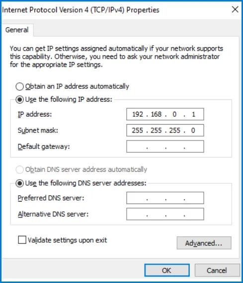
With EM-486 factory settings, for communication with it via Ethernet there are 2 possible ways: a) The network uses a router or other DHCP server, which assigns IP addresses to new devices. In this case, it is sufficient to connect the EM-486 to the network, and after some time the obtained IP address appears on the display. The address “0.0.0.0” means that the desired value has not been received yet. The address “192.168.0.111”, obtained after 30-60 seconds after running EM-486, may mean that getting address from the DHCP server failed and the device uses a static address. b) The network is not able to use DHCP, or EM-486 is connected directly to the computer (or another device-client on the same subnet). In this case, EM-486 will switch to static addressing after some time (30-60 seconds) after starting. A client device should use a mask 255.255.255.0 as a mask and address starting with 192.168.0. The fourth byte of the address can take any value in the range from 1 to 255, except for 111. If the connection between EM-486 and a client device is not provided directly but via a network with a number of devices, the mentioned address cannot be equal to any of the addresses of other devices on the subnet. If network has several devices with the mask and the first three bytes of the IP-address, which are different from those specified in the factory settings, or the EM-486 factory IP-address is already taken, the configurable device should be temporarily removed from the network to avoid addressing conflicts and establish a communication between this device and EM-486 directly. This will allow configuring the device and EM-486 for direct communication or switching EM-486 to the network. 2. Configuring the Client DeviceSection titled “2. Configuring the Client Device”The device addressing is set according to documents and software it uses. Below is an example of configuring the personal computer (PC) on Windows 7/8/10/11 to communicate directly with the EM-486 on factory settings. Opening Network Connections in WindowsSection titled “Opening Network Connections in Windows”For Windows 11:
For Windows 7/8/10:
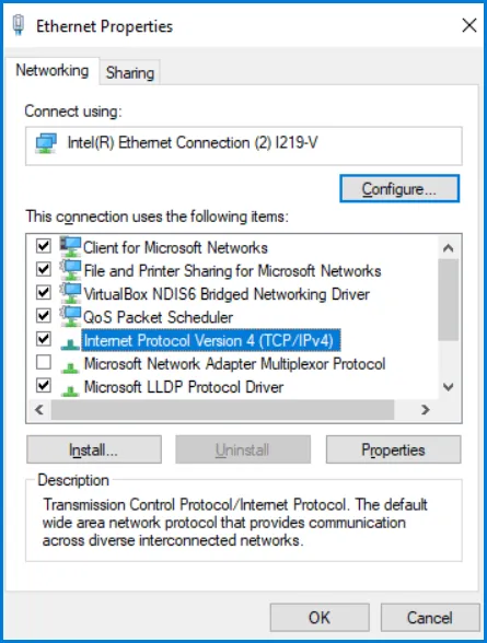
Configuring the Network ConnectionSection titled “Configuring the Network Connection”
Figure B.1 – Connection properties window in Windows OS
Figure B.2 – TCP/IPv4 properties window in Windows OS
3. Connection to Internet via EthernetSection titled “3. Connection to Internet via Ethernet”Use the following guidelines to connect the device to Internet:
4. GSM ConnectionSection titled “4. GSM Connection”Make sure that your tariff plan includes providing GPRS service (for connection to Internet) and/or receiving and sending SMS messages (for control via SMS). To connect the device via GSM, use the following recommendations:
5. Protection of ConnectionSection titled “5. Protection of Connection”EM-486 has basic protection against unauthorized access over network:
6. Connection to ServerSection titled “6. Connection to Server”EM-486 has the mode of constant communication with the data collection and management server. Data collected by the device is transferred and accumulated on the server; this data can accumulate in the internal memory of the device when connection is failed and transmitted to the server when connection is restored. As a server there can be, for example, the system Overvis (Internet-address is overvis.com). Overvis – is a system for monitoring and remote control of technological processes. Overvis makes it possible to read the data and make control over the devices including EM-486, provided there is a connection with them, and in the future to convert and view them in a convenient form, to receive alarm messages as SMS or E-Mail. EM-486 factory settings are prepared for connection to Overvis. Overvis system supports a special manner of identification which is used in EM-486. Thereat the devices are verified by a unique MAC-address which is sent to the server at each connection session. Device Registration MethodsSection titled “Device Registration Methods”The device registration for a user of the Overvis system is possible in two ways: a) If the device has a sticker with a QR code – it is required to read the code and follow the link or enter a link from the stickers manually and follow the instructions of the server. b) Enter the activation code to a user account of Overvis. The code represents the number of 8 characters and is displayed on the display and on the status page of the WEB interface of the device after connecting to the server. When you enter code, EM-486 is “attached” to a user account. Connecting to Overvis Using Activation CodeSection titled “Connecting to Overvis Using Activation Code”To connect a new device to the Overvis system using activation code you should:
Figure B.3 – Image of the activation code on the display (E - connection to server via Ethernet)
The message “no code” means that the device has been registered using the QR code on the sticker. Figure B.4 – Display image of activation state For information about EM-486 connection to other servers, contact the Device manufacturer. |
| | ||||||||||||||||||||||||||||||||||||||||||||||||||||||||||||||||||||||||||||||||||||||||||||||||||||||||||||||||||||||||||||||||||||||||||||||||||||||||||||||||||||||||||||||||||||||||||||||||||||||||
|---|---|---|---|---|---|---|---|---|---|---|---|---|---|---|---|---|---|---|---|---|---|---|---|---|---|---|---|---|---|---|---|---|---|---|---|---|---|---|---|---|---|---|---|---|---|---|---|---|---|---|---|---|---|---|---|---|---|---|---|---|---|---|---|---|---|---|---|---|---|---|---|---|---|---|---|---|---|---|---|---|---|---|---|---|---|---|---|---|---|---|---|---|---|---|---|---|---|---|---|---|---|---|---|---|---|---|---|---|---|---|---|---|---|---|---|---|---|---|---|---|---|---|---|---|---|---|---|---|---|---|---|---|---|---|---|---|---|---|---|---|---|---|---|---|---|---|---|---|---|---|---|---|---|---|---|---|---|---|---|---|---|---|---|---|---|---|---|---|---|---|---|---|---|---|---|---|---|---|---|---|---|---|---|---|---|---|---|---|---|---|---|---|---|---|---|---|---|---|---|---|
Appendix C: Task Files1. GeneralSection titled “1. General”After running, EM-486 starts execution of the program for logic of action, if it was placed earlier in the built-in memory. If there is no program in the built-in memory, EM-486 searches for and checks the task files placed in the folder “TASKS” on the memory card, provided the card is formatted in the FAT or FAT32 format. The correctly discovered files are read in the built-in memory and form the logic program of actions. Such a reading runs once after startup or after installing a new memory card, only if the built-in memory does not contain the programs. To clean the internal memory, you should:
The tab “Files” indicates the result of reading the folder “TASKS”, including the number of discovered and read files. If during reading and verifying the program errors were detected, then it indicates the type of error, file and line number of the file error. If the program consisted of several files in the folder “TASKS”, then the internal memory will read all files except those in which errors are detected. Therefore, during error correction you should compare the number of discovered and read files and if some were read, to clear again the internal memory to re-read the program. Files can have arbitrary names and extensions and placed in subfolders of the folder “TASKS”. Files placed directly in the folder TASKS, allow you to use MODBUS ID default in the text, equal to MODBUS ID of the device EM-486. Files placed in subfolders in the folder “TASKS” with names from “1” to “247”, allow to use the text MODBUS ID default name of the subfolder. Therefore, if the program logic is divided into tasks so that each is associated with its connected device, it is recommended that files relating only to EM-486, to be placed in the folder “TASKS” and files related to primarily the other device, to be put in a subfolder with the name of the MODBUS ID of this device. This allows you to change the list of managed devices by copying and renaming the subfolders, and create universal and portable files of the tasks. 2. Files of the TasksSection titled “2. Files of the Tasks”File of tasks describes repeated after a specified time interval the set of actions for gathering, processing and comparing the data and special actions after fulfillment of the preset conditions according to the processing results. The task file is divided into sections which in turn are divided into lines. The section is part of the file that starts with ”!” and the name of the section written in a row. Correct example: Incorrect example: If the section allows you to refer the lines in it, then all the lines of the section are numbered, otherwise instead of a number of the line will be put the sign 1. If a section with numbered lines is found for the first time, the numbering starts with 0, otherwise, numbering continues from the previous section of the same name. Correct example: Incorrect example: 2. Link to next line should be below the line that is referenced. Correct example: Incorrect example: The file should end with an empty line or a comment. The file should not have extra spaces, including at the end of lines. The file can contain comment lines that begin with Correct example: Incorrect example: Sections AssignmentSection titled “Sections Assignment”
2.1 META SectionSection titled “2.1 META Section”It contains the general information about the file and settings for its execution, and is responsible for the particularities of the program cycle fulfillment (the so-called “updates”), including the frequency of updates. Lines in it do not have numbering, instead of index is The types of the arguments are the following:
Types of ModifiersSection titled “Types of Modifiers”
Example: 2.2 DEVICES SectionSection titled “2.2 DEVICES Section”It contains the capabilities of MODBUS devices, the settings of not specified here devices will be treated the same as for the device with maximum features and functions. The lines in this section do not have numbering, instead of an index is MODBUS device ID: a number from 1 to 247. “0” – is the broadcast, it can be used to configure recording simultaneously to all devices that support the broadcasting (the argument 1 in this case is defined, but not used). Lines with different types or arguments, but with the same MODBUS ID are not permitted. These lines being in different files in the folder of programs are also considered to be incorrect. Arguments type: Types of RecordsSection titled “Types of Records”
Example: 2.3 PARAMS SectionSection titled “2.3 PARAMS Section”It contains parameters, their addressing, and conversion between types (how they are used by the device). When reading the settings are always converted from the specified type to the default type for the program EM-486 (INT32 – 32-bit signed integer). When recording the inverse transform is performed. The lines in this section are in ascending order, starting from zero. Each line has the following format:
Data TypesSection titled “Data Types”
Example: 2.4 VARS SectionSection titled “2.4 VARS Section”It contains variables, processing the parameters and other calculations (e.g. the sum of the parameters). The lines in this section are in ascending order, starting from zero. Each line has the following format:
The types of the arguments:
Types of SourcesSection titled “Types of Sources”
Example: 2.5 STRS SectionSection titled “2.5 STRS Section”It contains the text used as message for actions. The lines in this section are in ascending order, starting from zero. Each line has the following format:
Special sequences in the line text:
Example: 2.6 PHONES SectionSection titled “2.6 PHONES Section”It contains texts that are used for addressing SMS. The lines in this section are in ascending order, starting from zero. Each line has the following format:
Special sequences in the line text:
Example: 2.7 CONDS SectionSection titled “2.7 CONDS Section”It contains conditions for comparison of variables and triggering actions. The lines in this section are in ascending order, starting from zero. Each line has the following format:
The types of the arguments:
Condition TypesSection titled “Condition Types”
Example: 2.8 ACTS SectionSection titled “2.8 ACTS Section”It contains actions that can be performed (action is performed only by references from the section of the reactions REACTS, during the performance of the conditions indicated there). The lines in this section are in ascending order, starting from zero. Each line has the following format:
The types of the arguments:
Types of ActionsSection titled “Types of Actions”
Example: 2.9 REACTS SectionSection titled “2.9 REACTS Section”It contains the responses, a list of actions that must be performed under specified conditions. Lines do not have numbering, instead of an index is The types of the arguments:
Types of ResponseSection titled “Types of Response”
Example: 3. Examples of ProgramsSection titled “3. Examples of Programs”For complete example programs demonstrating task file usage, see Task File Examples. |
| | |||||||||||||||||||||||||||||||||||||||||||||||||||||||||||||||||||||||||||||||||||||||||||||||||||||||||||||||||||||||||||||||||||||||||||||||||||||||||||||||||||||||||||||||||||||||||||||||||||||||||||||||||||||||||||||||||||||||||||||||||||||||||||||||||||||||||||||||||||||||||||||||||||||||||||||||||||||||||||||||||||||||||||||||||||||||||||||||||||||||||||||||||||||||||||||||||||||||||||||||||||||||||||||||||||||||||||||||||||||||||||||||||||||||||||||||||||||||||||||||||||||||||||||||||||||||||||||||||||||||||||||||||||||||||||||||||||||||||||||||||||||||||||||||||||||||||||||||||||||||||||||||||||||||||||||||||||||||||||||||||||||||||||||||||||||||||||||||||||||||||||||||||||||||||||||||||||||||||||||||||||||||||||||||||||||||||||||||||||||||||||||||||||||||||||||||||||||||||||||||||||||||||||||||||||||||||||||||||||||||||||||||||||||||||||||||||||||||||||||||||||||||||||||||||||||||||||||||||||||||||||||||||||||||||||||||||||||||||||||||||||||||||||||||||||||||||||||||||||||||
|---|---|---|---|---|---|---|---|---|---|---|---|---|---|---|---|---|---|---|---|---|---|---|---|---|---|---|---|---|---|---|---|---|---|---|---|---|---|---|---|---|---|---|---|---|---|---|---|---|---|---|---|---|---|---|---|---|---|---|---|---|---|---|---|---|---|---|---|---|---|---|---|---|---|---|---|---|---|---|---|---|---|---|---|---|---|---|---|---|---|---|---|---|---|---|---|---|---|---|---|---|---|---|---|---|---|---|---|---|---|---|---|---|---|---|---|---|---|---|---|---|---|---|---|---|---|---|---|---|---|---|---|---|---|---|---|---|---|---|---|---|---|---|---|---|---|---|---|---|---|---|---|---|---|---|---|---|---|---|---|---|---|---|---|---|---|---|---|---|---|---|---|---|---|---|---|---|---|---|---|---|---|---|---|---|---|---|---|---|---|---|---|---|---|---|---|---|---|---|---|---|---|---|---|---|---|---|---|---|---|---|---|---|---|---|---|---|---|---|---|---|---|---|---|---|---|---|---|---|---|---|---|---|---|---|---|---|---|---|---|---|---|---|---|---|---|---|---|---|---|---|---|---|---|---|---|---|---|---|---|---|---|---|---|---|---|---|---|---|---|---|---|---|---|---|---|---|---|---|---|---|---|---|---|---|---|---|---|---|---|---|---|---|---|---|---|---|---|---|---|---|---|---|---|---|---|---|---|---|---|---|---|---|---|---|---|---|---|---|---|---|---|---|---|---|---|---|---|---|---|---|---|---|---|---|---|---|---|---|---|---|---|---|---|---|---|---|---|---|---|---|---|---|---|---|---|---|---|---|---|---|---|---|---|---|---|---|---|---|---|---|---|---|---|---|---|---|---|---|---|---|---|---|---|---|---|---|---|---|---|---|---|---|---|---|---|---|---|---|---|---|---|---|---|---|---|---|---|---|---|---|---|---|---|---|---|---|---|---|---|---|---|---|---|---|---|---|---|---|---|---|---|---|---|---|---|---|---|---|---|---|---|---|---|---|---|---|---|---|---|---|---|---|---|---|---|---|---|---|---|---|---|---|---|---|---|---|---|---|---|---|---|---|---|---|---|---|---|---|---|---|---|---|---|---|---|---|---|---|---|---|---|---|---|---|---|---|---|---|---|---|---|---|---|---|---|---|---|---|---|---|---|---|---|---|---|---|---|---|---|---|---|---|---|---|---|---|---|---|---|---|---|---|---|---|---|---|---|---|---|---|---|---|---|---|---|---|---|---|---|---|---|---|---|---|---|---|---|---|---|---|---|---|---|---|---|---|---|---|---|---|---|---|---|---|---|---|---|---|---|---|---|---|---|---|---|---|---|---|---|---|---|---|---|---|---|---|---|---|---|---|---|---|---|---|---|---|---|---|---|---|---|---|---|---|---|---|---|---|---|---|---|---|---|---|---|---|---|---|---|---|---|---|---|---|---|---|---|---|---|---|---|---|---|---|---|---|---|---|---|---|---|---|---|---|---|---|---|---|---|---|---|---|---|---|---|---|---|---|---|---|---|---|---|---|---|---|---|---|---|---|---|---|---|---|---|---|---|---|---|---|---|---|---|---|---|---|---|---|---|---|---|---|---|---|---|---|---|---|---|---|---|---|---|---|---|---|---|---|---|---|---|---|---|---|---|---|---|---|---|---|---|---|---|---|---|---|---|---|---|---|---|---|---|---|---|---|---|---|---|---|---|---|---|---|---|---|---|---|---|---|---|---|---|---|---|---|---|---|---|---|---|---|---|---|---|---|---|---|---|---|---|---|---|---|---|---|---|---|---|---|---|---|---|---|---|---|---|---|---|---|---|---|---|---|---|---|---|---|---|---|---|---|---|---|---|---|---|---|---|---|---|---|---|---|---|---|---|---|---|---|---|---|---|---|---|---|---|---|---|---|---|---|---|---|---|---|---|---|---|---|---|---|---|---|---|---|---|---|---|---|---|---|---|---|---|---|---|---|---|---|---|---|---|---|---|---|---|---|---|---|---|---|---|---|---|---|---|---|---|---|---|---|---|---|---|---|---|---|---|---|---|---|---|---|---|---|---|---|---|---|---|---|---|---|---|---|---|---|---|---|---|---|---|---|---|---|---|---|---|---|---|---|---|---|---|---|---|---|---|---|---|---|---|---|---|---|---|---|---|---|---|---|---|---|---|---|---|---|---|---|---|---|---|---|---|---|---|---|---|---|---|---|---|---|---|---|---|---|---|---|---|---|---|---|---|---|---|---|---|---|---|---|---|---|---|---|---|---|---|
Appendix D: Modbus RegistersFormat of Parameters Presentation in MODBUS RegistersSection titled “Format of Parameters Presentation in MODBUS Registers”
Parameter Groups Available via MODBUS ProtocolSection titled “Parameter Groups Available via MODBUS Protocol”
Device Describing ParametersSection titled “Device Describing Parameters”
Current Mode ParametersSection titled “Current Mode Parameters”
Control Commands (Register 120)Section titled “Control Commands (Register 120)”
Current Status ParametersSection titled “Current Status Parameters”
Access Flags (Register 122)Section titled “Access Flags (Register 122)”
Relay Control State Flags (Register 179)Section titled “Relay Control State Flags (Register 179)”
Device Settings ParametersSection titled “Device Settings Parameters”Ethernet NetworkSection titled “Ethernet Network”
GSM NetworkSection titled “GSM Network”
MODBUS TCP ClientsSection titled “MODBUS TCP Clients”
MODBUS NetworkSection titled “MODBUS Network”
Connection to Data Accumulation ServerSection titled “Connection to Data Accumulation Server”
SecuritySection titled “Security”
SensorsSection titled “Sensors”
MiscellaneousSection titled “Miscellaneous”
Connection to the First Remote Server of MODBUS TCPSection titled “Connection to the First Remote Server of MODBUS TCP”
CountersSection titled “Counters”
Automatic Transition to Daylight Saving TimeSection titled “Automatic Transition to Daylight Saving Time”
Calculation of Sunrises and SunsetsSection titled “Calculation of Sunrises and Sunsets”
The Connection to the Server of NTP Clock SynchronizationSection titled “The Connection to the Server of NTP Clock Synchronization”
LoggingSection titled “Logging”
EncryptionSection titled “Encryption”
SubscribersSection titled “Subscribers”
Connect to the Second Remote MODBUS TCP ServerSection titled “Connect to the Second Remote MODBUS TCP Server”
Connection to the Third Remote MODBUS TCP ServerSection titled “Connection to the Third Remote MODBUS TCP Server”
Preset Passwords for Access to Remote ServersSection titled “Preset Passwords for Access to Remote Servers”
User SettingsSection titled “User Settings”
Setting the ClockSection titled “Setting the Clock”
|
| | ||||||||||||||||||||||||||||||||||||||||||||||||||||||||||||||||||||||||
|---|---|---|---|---|---|---|---|---|---|---|---|---|---|---|---|---|---|---|---|---|---|---|---|---|---|---|---|---|---|---|---|---|---|---|---|---|---|---|---|---|---|---|---|---|---|---|---|---|---|---|---|---|---|---|---|---|---|---|---|---|---|---|---|---|---|---|---|---|---|---|---|---|
Appendix E: Saving Data to Memory Card1. General DataSection titled “1. General Data”The EM-486 supports microSD compatible memory cards formatted in FAT/FAT32. Only the first volume of the card is used (the maximum usable capacity on the card is 32 GB). The card can be inserted before powering on the device or while the device is in operation. EM-486 uses a memory card for the following actions:
When the device is started or when a memory card is inserted, its parameters and firmware update files are checked (it may take up to 30 seconds). After that, the card can be used for other actions. When the device is restarted, when the supply voltage drops below the value specified in the settings (see register 724 in Appendix D), EM-486 safely ejects the memory card, saving temporary data and closing open files. 2. Reading Task Files with Programmable Logic of WorkSection titled “2. Reading Task Files with Programmable Logic of Work”EM-486 reads task files from the “TASKS” folder and its subfolders on the memory card (see Appendix C - Task Files). 3. Logging of Collected DataSection titled “3. Logging of Collected Data”EM-486 saves the collected data to the log in the “LOGS\TASKS” folder on the memory card. The order of data collection and conditions for logging are specified in the task files (see Appendix C). If the folder is missing, it will be created. For each month, a subfolder is created with a name in the format: Where:
In this subfolder, for each day of the month, a file is created with the name in the format: Where:
In the event of write errors, data remains in the write queue in temporary memory, and write attempts continue until the data is written or remains in the queue for more than 10 minutes. After that, the data is removed from the write queue, while the number of bytes that could not be written is added together, and this information about losses can be added to the log later. 3.1 Logging to Data Bytes FilesSection titled “3.1 Logging to Data Bytes Files”When the byte log format is selected, the EM-486 saves the collected data in a compact form to files with the “DAT” extension. Records of a fixed size of 16 bytes are appended to the files. Each record can contain the value of one parameter or a service message. Service Record FormatSection titled “Service Record Format”
Parameter Record FormatSection titled “Parameter Record Format”
3.2 Logging to Text Table FilesSection titled “3.2 Logging to Text Table Files”In a case of select the tabular format of the log, EM-486 saves the collected data in text form to files with the “CSV” extension. Records are added to the files in the form of text strings consisting of fields of variable length, separated by the character selected in the settings (see register 725). Lines are separated by a standard pair of characters (CR + LF for line feed). The maximum record length without adding a comment to the end of the line is 70 bytes. When using the logging command with a comment, the maximum line length depends on the format of the comment line and can be up to 200 bytes plus the length of the values substituted into the comment. Text Table Record FormatSection titled “Text Table Record Format”
3.3 Filling the Memory CardSection titled “3.3 Filling the Memory Card”The time it takes for an empty memory card to be full can be calculated using the formula: Tfull ≈ (Vfree × Tnew) / (Npar × Lsiz) Where:
Examples:
When the logger mode is turned on (see register 727), after the free space on the memory card is exhausted, the oldest files can be deleted before writing new data. When the recorder mode is off, new data recording will be paused until space becomes available. 4. Export and Import SettingsSection titled “4. Export and Import Settings”EM-486 can export the saved settings from the internal memory to the “SETTINGS\EM486SET.DAT” file, or import the settings from this file and save them to the internal memory. To export or import settings:
The file can be up to 16 kB in size. 5. Saving Pulse CountersSection titled “5. Saving Pulse Counters”EM-486 can save pulse counters at inputs in the “LOGS\COUNTERS” folder on the memory card. Files with names similar to the names of the log files in the data byte format are created in this folder (see Section 3). The size of each record is 24 bytes. The file size limit is 256 kB. When reading counters from a memory card after starting the device, the old files can be deleted if their number exceeds 3 files. 6. Firmware UpdatesSection titled “6. Firmware Updates”EM-486 can update the firmware (see Appendix G - Firmware Update) with one of three files:
Files can be up to 10 MB each in size. |
| | ||||||||||||||||||||||||||||||||||||||||||||||||||||||||||||||||||||||||||||||||||||
|---|---|---|---|---|---|---|---|---|---|---|---|---|---|---|---|---|---|---|---|---|---|---|---|---|---|---|---|---|---|---|---|---|---|---|---|---|---|---|---|---|---|---|---|---|---|---|---|---|---|---|---|---|---|---|---|---|---|---|---|---|---|---|---|---|---|---|---|---|---|---|---|---|---|---|---|---|---|---|---|---|---|---|---|---|
Appendix F: Web InterfacesTo access the device using a browser, the EM-486 expects an Ethernet connection to port 80 and HTTP transmissions. To connect in the address bar of the browser, call the IP address of the device (to display the address on the EM-486 display, see section 5.3.1 of the manual). The browser displays WEB pages that allow you to read the status of the device, set parameters, call MODBUS functions and perform file operations on the memory card. In addition, the HTTP connection can be used by other applications to automatically invoke MODBUS functions using the API. EM-486 supports API in two formats: JSON and XML. For example, if the IP address of the device is “192.168.0.111”, then the API JSON request without parameters will look like API Response Without ParametersSection titled “API Response Without Parameters”An example of a response to a request is given below. JSON format: XML format: Response Fields DescriptionSection titled “Response Fields Description”
AuthorizationSection titled “Authorization”To access MODBUS authorization is required, which can be done in two ways:
Upon successful authorization, the device returns a response with a redirection to the session page, for example, Authorization Response ExampleSection titled “Authorization Response Example”The response to the request JSON format: XML format: Authorization Response FieldsSection titled “Authorization Response Fields”
MODBUS CallSection titled “MODBUS Call”To call MODBUS, the following parameters are used:
MODBUS Call Response ExampleSection titled “MODBUS Call Response Example”The answer to JSON format: XML format: Successful MODBUS Call Response FieldsSection titled “Successful MODBUS Call Response Fields”
MODBUS Error Response FieldsSection titled “MODBUS Error Response Fields”
|
| | ||||||||||||||||||||||||||||||||||||||||||||||||||||||||||||||||||||||||||||||||||||||||||||||||||||||||||||||||||||||||||||||||||
|---|---|---|---|---|---|---|---|---|---|---|---|---|---|---|---|---|---|---|---|---|---|---|---|---|---|---|---|---|---|---|---|---|---|---|---|---|---|---|---|---|---|---|---|---|---|---|---|---|---|---|---|---|---|---|---|---|---|---|---|---|---|---|---|---|---|---|---|---|---|---|---|---|---|---|---|---|---|---|---|---|---|---|---|---|---|---|---|---|---|---|---|---|---|---|---|---|---|---|---|---|---|---|---|---|---|---|---|---|---|---|---|---|---|---|---|---|---|---|---|---|---|---|---|---|---|---|---|---|---|---|
Appendix G: Updating FirmwareGeneral InformationSection titled “General Information”To upgrade the integrated software, EM-486 uses files Transmitting the EM-486 Updating FilesSection titled “Transmitting the EM-486 Updating Files”To transfer the update files, it is possible in two ways:
Firmware Updating ModeSection titled “Firmware Updating Mode”The device can be set in mode of firmware updating after power supply and restart. The setting in that mode is made automatically (at updating via WEB-interface or at update failure) or manually (at the button “R” being pressed during a startup). Entering the Mode of Software UpdatingSection titled “Entering the Mode of Software Updating”
Selection of Updating FileSection titled “Selection of Updating File”After manual entering in mode of updating, select the file of updating. To cancel the updating, cut off the power supply of EM-486 or wait until automatic completion of updating mode.
Updating of Integrated FirmwareSection titled “Updating of Integrated Firmware”At automatic entering into the mode of firmware updating or at manual selection of file, the updating is made from the file.
Error CodesSection titled “Error Codes”The errors detected during the updating process are shown on the display. Codes of Warning in Software Updating ModeSection titled “Codes of Warning in Software Updating Mode”
|
| |
|---|
Task File ExamplesBelow there are examples of finished programs, each consists of a single task file. To run the sample on the EM-486 it is necessary:
Available ExamplesSection titled “Available Examples”
|
| |
|---|
Relay Control Based on OM-310 FaultThis example describes a program that in the event of fault of the OM-310 will turn on the 1st relay on EM-486. In the text 3 – MODBUS ID of the device is OM-310; 240 is the register address which is monitored for the accident. |
| |
|---|
Hysteresis Control for TR-101In this example, the program controls the hysteresis value on the second channel of the TR-101 device, depending on the temperature on the sensor of the first input of EM-486. In the text 16 – MODBUS ID of the device is TR-101; 47 is the address of register for the hysteresis of the second channel TR-101. The program uses registers in the field of current user settings 5500-5749. Registers 5500 and 5501 are reserved for the values respectively of the lower and upper temperature limits and the registers 5502 and 5503 are for the hysteresis value to be set in TR-101 if achieving the temperature respectively the lower or upper limits. These registers are read-only. To change them, you should be in configuration mode (see para. 5.3.4), then write the desired values to addresses of the respective editable settings. These addresses are obtained by subtracting 250 from the address current value. Thus, temperature limits are recorded into the registers 5250 and 5251, and the hysteresis – 5252 and 5253. Then, in order for the changes to take effect, you need to give the commands “Save” and “Apply” (for example by writing 4 to the register 120). |
| |
|---|
Temperature Alarm with SMSIn this example, a program is described that reads the temperature measured by OB-215, and when the temperature exceeds -15 degrees for more than 10 minutes, sends an SMS and starts logging the temperature values. In text 11 - MODBUS ID of the OB-215 device; 6 - address of the register from which the temperature is read. |
| | ||||||
|---|---|---|---|---|---|---|
Simple Timer-Based Relay ControlThis program example switches the EM-486’s relay on/off depending on time of day. At the specified times of the day it switches the relay OFF and ON. Required condition is that OFF-time should be before (less than) ON-time. The program is controlled through Overvis using registers on EM-486 device.
This program can be modified to control the OB-215 relay with EM-486. In that case, parameter |
| | ||||||
|---|---|---|---|---|---|---|
Simple Temperature ControlThis example program switches the EM-486 relay on/off depending on sensor reading. If sensor reading is below minimum value, then relay is turned ON. If sensor reading is above maximum value, then relay is turned OFF. In between - relay state is undefined (not controlled by EM-486). The program is controlled through Overvis using registers on EM-486 device.
This program can easily be modified to control the OB-215 relay with EM-486. In that case, parameter |
| | ||||||||||||||||||
|---|---|---|---|---|---|---|---|---|---|---|---|---|---|---|---|---|---|---|
Astronomical Timer / Light Sensor
This example EM-486 program turns on/off the OB-215 relay based on sunset/sunrise or light sensor connected to OB-215. It also includes additional energy saving interval (during night) when the relay should be switched off.
The program is controlled through Overvis using registers on EM-486 device. Logic mode setting:
Astronomical timer mode settings:
Sensor-based mode settings:
This program can be easily modified to work on EM-486 without OB-215. In that case, actions (section |