Novatek-Electro EM-483 Documentation
https://www.overvis.com/docs/en/em-483/
2026-07-30
| |
|---|
Novatek-Electro EM-483
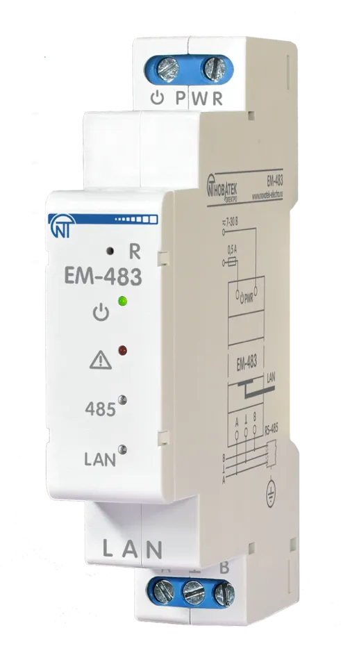
The EM-483 is a microprocessor protocol converter manufactured by NOVATEK-ELECTRO LTD. It provides data exchange over 10BASE-T and 100BASE-T Ethernet networks with equipment supplied with an RS-485 interface. The EM-483 provides MODBUS server functions to connect MODBUS clients over an Ethernet network. The product redirects MODBUS requests from clients to devices on the MODBUS network and returns responses from the devices to the clients. EM-483 can also be used in tunnel mode for direct data transmission between clients and RS-485 devices using protocols other than MODBUS. Key FeaturesSection titled “Key Features”
Common Use CasesSection titled “Common Use Cases”
DocumentationSection titled “Documentation”
Technical ReferenceSection titled “Technical Reference”
ResourcesSection titled “Resources”
SupportSection titled “Support”
|
| | ||||||||||||||||||||||||||||||||||||||||||||||||||||||||||||||||||||||||||||||||||
|---|---|---|---|---|---|---|---|---|---|---|---|---|---|---|---|---|---|---|---|---|---|---|---|---|---|---|---|---|---|---|---|---|---|---|---|---|---|---|---|---|---|---|---|---|---|---|---|---|---|---|---|---|---|---|---|---|---|---|---|---|---|---|---|---|---|---|---|---|---|---|---|---|---|---|---|---|---|---|---|---|---|---|
EM-483 Operating Manual
The Protocol Converter EM-483 (hereinafter referred to as “Product”, “EM-483”) is a microprocessor device manufactured by NOVATEK-ELECTRO LTD. The product is designed for data exchange over a 10BASE-T and 100BASE-T Ethernet network with equipment supplied with an RS-485 interface. The EM-483 provides for MODBUS server functions to connect MODBUS clients over an Ethernet network. The product redirects MODBUS requests from clients to devices on the MODBUS network and returns responses from the devices to the clients. EM-483 can also be used in tunnel mode for direct data transmission between clients and RS-485 devices using protocols other than MODBUS. The EM-483 provides for:
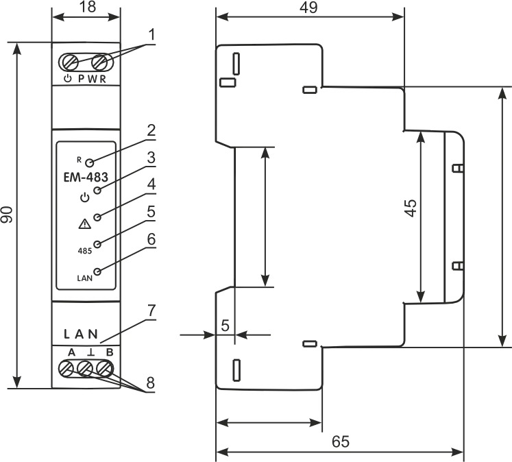
Overall and Mounting DimensionsSection titled “Overall and Mounting Dimensions”
Figure 1 – Overall and mounting dimensions and controls
Firmware VersionsSection titled “Firmware Versions”
Terms and AbbreviationsSection titled “Terms and Abbreviations”
Operation ConditionsSection titled “Operation Conditions”The product is intended for operation in the following conditions:
Technical SpecificationsSection titled “Technical Specifications”
The Product remains functional at any position in space. Case material: self-extinguishing plastic. The product meets the requirements of the following: EN 60947-1; EN 60947-6-2; EN 55011; EN 61000-4-2. Harmful substances in an amount exceeding the maximum permissible concentrations are absent. ConnectionSection titled “Connection”
Figure 2 – Connection diagram For a reliable contact, tighten the terminal screws with the force 0.4 N·m. To ensure the reliability of electrical connections, use flexible (stranded) wires, the ends of which must be stripped of insulation by 5±0.5 mm and compressed with bushing tips. It is recommended to use a wire with a cross section of at least 1 mm². When connecting to the RS-485 bus, use a twisted pair cable. Cat. 1 or higher. A shielded grounded cable is recommended. When fixing the wires, avoid mechanical damage, twisting or wearing down the insulation of the wires. The connection of EM-483 is made according to the scheme shown in Figure 2, in the following order:
OperationSection titled “Operation”A 32-bit RISC processor with ARM architecture routes data between a MODBUS RTU/ASCII network (RS-485) and the Ethernet network (10BASE-T/100BASE-T). The speed and availability of direct memory access channels allow you to operate with high-speed data streams. The indicators indicate the status of the connections and the data flow over the MODBUS and Ethernet networks. The «R» button allows you to restart the EM-483 without disconnecting it from the network, or reset the settings to factory values. The product is equipped with a memory for storing settings. Each product receives a globally unique MAC address during manufacturing and can connect to local networks that have a secure Internet connection. Using the ProductSection titled “Using the Product”After power is applied, the «⚠» and «485» indicators light up, and EM-483 initializes the transceivers. After that, both lights go out for 0.5 seconds, and the product starts performing server functions (the connection to the Ethernet network may take longer depending on the settings of the product and other devices connected to the network). The EM-483 is waiting for an Ethernet connection. If the «LAN» indicator lights up, the network connection has been successful. The flashing «LAN» indicator shows that data is passing through the network. Operation of EM-483 over the HTTP ProtocolSection titled “Operation of EM-483 over the HTTP Protocol”EM-483 is waiting for an HTTP Ethernet connection to port 80. Connection from a PC can be made using a WEB browser. When the client is connected to port 80, the product expects requests from the client to receive HTML pages. Parameters can be specified in the request. In response to the correct request, the parameters are processed, and the text of the selected page is transmitted to the client in HTML format (or in JSON or XML format for API requests, see Appendix B - WEB Interfaces). If the request does not specify an existing page, the title page will be returned. After the page is passed, the product disconnects the client and waits for the connection again. Operation of EM-483 via the MODBUS ProtocolSection titled “Operation of EM-483 via the MODBUS Protocol”During operation, EM-483 is waiting for an Ethernet connection over the MODBUS TCP protocol to port 502. The MODBUS TCP connection port can be changed by the user. The connection from a PC can be made using any programs – MODBUS TCP clients. The application «MODBUS TCP client» is available for download on the manufacturer’s website www.novatek-electro.com in the section «Software». An additional port for MODBUS RTU or MODBUS ASCII connections over TCP can also be specified in the settings. When requesting a client connection to a MODBUS port, EM-483 checks the list of available connections. If all connections are busy, the connection is rejected; otherwise, it is added to the internal list of serviced clients (no more than four clients). EM-483 is waiting for a MODBUS request:
When a request is received from a client, it is analyzed and, depending on the code of the requested function and the current rights of the client, it is either processed or blocked. When blocking a request, EM-483 can generate and transmit to the client a user-specified MODBUS exception code (by default, code 1). The client’s rights are determined by the passwords entered after the connection. If the request is addressed to EM-483, the product does not redirect the request, but processes it and transmits the response to the client. In the master mode via the RS-485 interface, requests to other devices are redirected to the MODBUS network, and a response is expected from the device in the MODBUS network – the «485» indicator lights up. If the data is received or the waiting time has expired, the «485» indicator goes out. In the remote server redirection mode, if a connection is established with a remote MODBUS TCP server, requests to other devices are also sent to this server, and a response is expected from it. If the request could not be redirected (for example, in the slave mode, if the connection to the remote MODBUS TCP server was terminated), EM-483 can generate and transmit to the client the user-specified MODBUS exception code (by default, code 10). If there is no response, EM-483 can generate and transmit the user-specified MODBUS exception code (by default, code 11) to the client. If a response to the request has been received, EM-483 transmits it to the client that sent the request. EM-483 Operation in Tunnel ModeSection titled “EM-483 Operation in Tunnel Mode”In tunnel mode EM-483 receives data “as is”, without protocol check, and sends them to all other directions, for which this mode is selected. This allows transmitting data in a format other than MODBUS protocol. For example, arbitrary data received via RS-485 can be forwarded to a remote server, and vice versa. The tunnel can be selected separately for each connection to the remote server and for the RS-485 interface. In the latter case, since the data format for incoming connections to the optional TCP port is the same as for RS-485, the tunnel mode will be enabled for these connections as well. A data packet from one direction is received in its entirety (for Ethernet TCP it is the content of one TCP packet, for RS-485 the packet length is determined by the MODBUS RTU maximum pause rules), then sent to the other tunnel directions in turn. The maximum length of a data packet is 254 bytes. Setting UpSection titled “Setting Up”The configurable parameters are described in Appendix C - MODBUS Registers. The parameters are saved when the power is turned off. There are two ways to configure the product:
Restarting the product or resetting the settings to make them comply with the factory values is performed using the «R» button accessible through the hole on the front panel. The button must be pressed by a thin non-conductive object. Reset to Manufacturer’s DefaultsSection titled “Reset to Manufacturer’s Defaults”
Restart with Saved SettingsSection titled “Restart with Saved Settings”
Configuring EM-483 via the MODBUS InterfaceSection titled “Configuring EM-483 via the MODBUS Interface”Configuration via the MODBUS interface is performed when connecting to the product using a MODBUS client IP address (factory value – 192.168.0.111) specifying the MODBUS identifier EM-483 (factory value – 111). To configure the parameters, write the password string into the password input parameter (see Current Mode Parameters). The factory password value is «11111», i.e. to write the factory password into registers 0 to 4, write the number 49 – the ASCII code of the unit. If the password is specified correctly, the mode register (see Current State Parameters) will take the value «1» – the setting mode. In the setup mode, the control command parameter is available for recording, as well as the setup parameters (listed in Settings). After writing the desired values into the configuration parameters registers, write the value «2» – the «Save» command to the control command parameter. The correctness of the saved parameters values can be checked by comparing the sets of configurable parameters and the saved parameters. If the sets match, the new settings have been accepted and saved. To apply parameters without restarting the product, write the value «4» into the control command parameter – the «Save and Apply» command. Only MODBUS and custom parameters can be applied without restarting the product. The correctness of the saved parameters values can be checked by comparing the sets of configurable parameters and the current parameters. If the sets match, the new settings have been accepted and saved. To cancel changes in the parameters before saving them, write the value «9» in the control command parameter – the «Cancel» command. In this case, the configurable parameters take the values of the saved ones. To reset the saved parameters to the factory values in the setup mode, write the value «444» in the control command parameter – the «Return to Factory» command. In order for the stored parameter values to take effect, the product must be restarted. Via the MODBUS interface, the restart is performed by writing the value «1» to the control command parameter – the «Restart» command. To exit the setup mode, write 0 to the first register of the password input parameter. In this case, all the password input registers and the control command register are cleared (they take the value «0»). Configuring EM-483 via the WEB InterfaceSection titled “Configuring EM-483 via the WEB Interface”The configuration via the WEB-interface is performed using a WEB-browser. Write the IP address of the product in the address bar of the browser (the factory value is 192.168.0.111) and select the transition to the specified address. The main page will be displayed with the tab titles for switching over to other modes. To configure the product parameters, select the «Settings» tab. You will be prompted for a password to access the settings (the factory value is «11111»). After entering the password and pressing the «Login» button, if the password is specified correctly, access to the configuration mode must be allowed. The settings page appears. If the password is incorrect, you will be prompted for the password again. The settings on the settings page are grouped by purpose and divided into bookmarks. Non-configurable parameters and measurements are available on the «Status» tab. The settings on the other tabs are listed in the Settings. After making changes to the parameters, click the «Save» button. In this case, the entered parameters will be checked. If there are no errors in the parameter values, the parameters will be stored in the EM-483 memory (the new parameters will take effect after the next parameter application or restart). If errors are found in the parameters when clicking the «Save» button, none of the parameters are saved, and the names of the erroneous parameters are highlighted in red. To apply the parameters without restarting the product, click the «Apply» button at the bottom of the page. In this case, the entered parameters will be checked. If there are no errors in the parameter values, the parameters will be stored in the EM-483 memory and will take effect. Only MODBUS and custom parameters can be applied without restarting. When you click on the «Return to Factory» button, all parameters take their factory values. When the «Restart» button is clicked, all connections and incoming/outgoing operations are interrupted, and the EM-483 is restarted. If changes in the parameters have been made and stored in the product’s memory before, these changes will take effect. When you click on the «Exit» button, the setup mode is closed, and the password request is displayed again. Firmware UpdateSection titled “Firmware Update”EM-483 stores two update files in its memory:
Any of these files can be obtained from the EM-483 memory (for loading into another EM-483 product). The installed firmware can be updated from these files remotely via MODBUS or WEB-interface. Transfer of EM-483 Update FilesSection titled “Transfer of EM-483 Update Files”Remote download via MODBUS:
Upload via WEB-interface:
To upload a file to EM-483:
To get a file from EM-483:
To erase the contents of the EM-483 file, click the «Erase» button. Firmware Update by External CommandSection titled “Firmware Update by External Command”Remote software update via MODBUS:
Update via WEB-interface:
The product will automatically restart and enter the update mode. Wait for the software update, the process may take from 1 to 3 minutes. Then connect to the EM-483 (via WEB-interface or MODBUS-interface). Check the version number and make sure that the update was successful. Complete SetSection titled “Complete Set”
MaintenanceSection titled “Maintenance”Recommended frequency of maintenance is every six months. Maintenance Procedure:
Safety PrecautionsSection titled “Safety Precautions”It is not allowed water penetration on terminals and internal elements of the product. During operation and maintenance, the regulatory document requirements must be met, namely:
Transportation and StorageSection titled “Transportation and Storage”The product in the original package is permitted to be transported and stored at the temperature from minus 45 to +60 °C and relative humidity of no more than 80 %. Service Life and Manufacturer WarrantySection titled “Service Life and Manufacturer Warranty”
During the warranty period of operation (in the case of failure of the product) the manufacturer is responsible for free repair of the device. Warranty service is performed at the place of purchase or by the manufacturer of the product. Post-warranty service of the product is performed by the manufacturer at current rates. Before sending for repair, the product should be packed in the original or other packing which prevents mechanical damage. Manufacturer ContactSection titled “Manufacturer Contact”“Novatek-Electro” Ltd.
|
| |
|---|
Appendix A: Connecting to the ServerThe EM-483 has a continuous communication mode with the data acquisition and management server. The server can be, for example, the Overvis system (Internet-address «overvis.com»). About OvervisSection titled “About Overvis”Overvis is a system for monitoring and remote control of technological processes. Overvis allows you to:
The factory settings of EM-483 are prepared for connection to Overvis. Product RegistrationSection titled “Product Registration”The Overvis system supports a special identification method used in the product. In this case, the products are recognized by a unique MAC address, which is transmitted to the server each time you connect. There are two ways to register the product for the user of the Overvis system: Option A: QR Code RegistrationSection titled “Option A: QR Code Registration”If the product has a sticker with a QR-code, read the code and click on the link or enter the link from the sticker manually and then follow the instructions of the server. Option B: Activation Code RegistrationSection titled “Option B: Activation Code Registration”Specify the activation code in the Overvis user account. The code is a number of 8 characters displayed on the status page of the product WEB-interface after connecting to the server. When you enter the code, the EM-483 “links” to the user account. Connecting a New Product to OvervisSection titled “Connecting a New Product to Overvis”To connect a new product to the Overvis system using an activation code, you must:
The message «No Code» means that the product was registered using the QR-code on the sticker. |
| | ||||||||||||||||||||||||||||||||||||||||||||||||||||||||||||||||||||||||||||||||||||
|---|---|---|---|---|---|---|---|---|---|---|---|---|---|---|---|---|---|---|---|---|---|---|---|---|---|---|---|---|---|---|---|---|---|---|---|---|---|---|---|---|---|---|---|---|---|---|---|---|---|---|---|---|---|---|---|---|---|---|---|---|---|---|---|---|---|---|---|---|---|---|---|---|---|---|---|---|---|---|---|---|---|---|---|---|
Appendix B: Web InterfacesTo access the product using a browser, EM-483 waits for an Ethernet connection to port 80 and for HTTP protocol transfers. To make a connection, call the IP address of the product (the factory setting is 192.168.0.111) from the browser’s address bar. The browser displays WEB pages that allow you to read the product status, configure parameters, call the MODBUS functions, and perform file operations. In addition, the HTTP connection can be used by other applications to automatically call the MODBUS functions using API. EM-483 supports API in two formats: JSON and XML. For example, if the IP-address of the product is “192.168.0.111”, then the JSON API request without parameters will look like API Response Without ParametersSection titled “API Response Without Parameters”An example of a response to a request is given below. JSON format: XML format: Response Fields DescriptionSection titled “Response Fields Description”
AuthorizationSection titled “Authorization”Access to MODBUS requires authorization, which can be performed in two ways:
Upon successful authorization, the product returns the response redirecting it to the session page, for example, Authorization Response ExampleSection titled “Authorization Response Example”The response to the request JSON format: XML format: Authorization Response FieldsSection titled “Authorization Response Fields”
MODBUS Call ParametersSection titled “MODBUS Call Parameters”The parameters listed below are used to call MODBUS.
MODBUS Call Response ExampleSection titled “MODBUS Call Response Example”The response to JSON format: XML format: Successful MODBUS Call Response FieldsSection titled “Successful MODBUS Call Response Fields”
MODBUS Call Error Response FieldsSection titled “MODBUS Call Error Response Fields”
|
| | |||||||||||||||||||||||||||||||||||||||||||||||||||||||||||||||||||||||||||||||||||||||||||||||||||||||||||||||||||||||||||||||||||||||||||||||||||||||||||||||||||||||||||||||||||||||||||||||||||||||||||||||||||||||||||||||||||||||||||||||||||||||||||||||||||||||||||||||||||||||||||||||||||||||||||||||||||||||||||||||||||||||||||||||||||||||||||||||||||||||||||||||||||||||||||||||||||||||||||||||||||||||||||||||||||||||||||||||||||||||||||||||||||||||||||||||||||||||||||||||||||||||||||||||||||||||||||||||||||||||||||||||||||||||||||||||||||||||||||||||||||
|---|---|---|---|---|---|---|---|---|---|---|---|---|---|---|---|---|---|---|---|---|---|---|---|---|---|---|---|---|---|---|---|---|---|---|---|---|---|---|---|---|---|---|---|---|---|---|---|---|---|---|---|---|---|---|---|---|---|---|---|---|---|---|---|---|---|---|---|---|---|---|---|---|---|---|---|---|---|---|---|---|---|---|---|---|---|---|---|---|---|---|---|---|---|---|---|---|---|---|---|---|---|---|---|---|---|---|---|---|---|---|---|---|---|---|---|---|---|---|---|---|---|---|---|---|---|---|---|---|---|---|---|---|---|---|---|---|---|---|---|---|---|---|---|---|---|---|---|---|---|---|---|---|---|---|---|---|---|---|---|---|---|---|---|---|---|---|---|---|---|---|---|---|---|---|---|---|---|---|---|---|---|---|---|---|---|---|---|---|---|---|---|---|---|---|---|---|---|---|---|---|---|---|---|---|---|---|---|---|---|---|---|---|---|---|---|---|---|---|---|---|---|---|---|---|---|---|---|---|---|---|---|---|---|---|---|---|---|---|---|---|---|---|---|---|---|---|---|---|---|---|---|---|---|---|---|---|---|---|---|---|---|---|---|---|---|---|---|---|---|---|---|---|---|---|---|---|---|---|---|---|---|---|---|---|---|---|---|---|---|---|---|---|---|---|---|---|---|---|---|---|---|---|---|---|---|---|---|---|---|---|---|---|---|---|---|---|---|---|---|---|---|---|---|---|---|---|---|---|---|---|---|---|---|---|---|---|---|---|---|---|---|---|---|---|---|---|---|---|---|---|---|---|---|---|---|---|---|---|---|---|---|---|---|---|---|---|---|---|---|---|---|---|---|---|---|---|---|---|---|---|---|---|---|---|---|---|---|---|---|---|---|---|---|---|---|---|---|---|---|---|---|---|---|---|---|---|---|---|---|---|---|---|---|---|---|---|---|---|---|---|---|---|---|---|---|---|---|---|---|---|---|---|---|---|---|---|---|---|---|---|---|---|---|---|---|---|---|---|---|---|---|---|---|---|---|---|---|---|---|---|---|---|---|---|---|---|---|---|---|---|---|---|---|---|---|---|---|---|---|---|---|---|---|---|---|---|---|---|---|---|---|---|---|---|---|---|---|---|---|---|---|---|---|---|---|---|---|---|---|---|---|---|---|---|---|---|---|---|---|---|---|---|---|---|---|---|---|---|---|---|---|---|---|---|---|---|---|---|---|---|---|---|---|---|---|---|---|---|---|---|---|---|---|---|---|---|---|---|---|---|---|---|---|
Appendix C: Modbus RegistersParameter Sets Available via MODBUS ProtocolSection titled “Parameter Sets Available via MODBUS Protocol”The parameter sets available via the MODBUS protocol are listed below. The internal structure of all parameter sets is similar to that of the set described in Settings, except for the start address.
Format of Parameters Presentation in MODBUS RegistersSection titled “Format of Parameters Presentation in MODBUS Registers”
Device Describing ParametersSection titled “Device Describing Parameters”
Current Mode ParametersSection titled “Current Mode Parameters”
Current State ParametersSection titled “Current State Parameters”
Access Mode Flags (Register 122)Section titled “Access Mode Flags (Register 122)”
Firmware Download Status Flags (Register 2004)Section titled “Firmware Download Status Flags (Register 2004)”
SettingsSection titled “Settings”Ethernet NetworkSection titled “Ethernet Network”
MODBUS NetworkSection titled “MODBUS Network”
Connecting to the Data Collection ServerSection titled “Connecting to the Data Collection Server”
ProtectionSection titled “Protection”
MiscellaneousSection titled “Miscellaneous”
Connecting to the First Remote ServerSection titled “Connecting to the First Remote Server”
* In virtual identifiers mode, before redirecting a request to a remote server MODBUS TCP, the virtual identifier of the destination from the request is replaced with the real one so that the numbering in the server range starts with 1. For example, for the range 15-17, the virtual ID 16 will be replaced with the real one 2. The broadcast ID 0 is processed without changes. Connecting to the Second Remote ServerSection titled “Connecting to the Second Remote Server”Similar to registers 640–649, with the factory value of the remote server IP address being 192.168.0.113.
Connecting to the Third Remote ServerSection titled “Connecting to the Third Remote Server”Similar to registers 640–649, with the factory value of the remote server IP address being 192.168.0.114.
Connecting to the Fourth Remote ServerSection titled “Connecting to the Fourth Remote Server”Similar to registers 640–649, with the factory value of the remote server IP address being 192.168.0.115.
Connecting to the Fifth Remote ServerSection titled “Connecting to the Fifth Remote Server”Similar to registers 640–649, with the factory value of the remote server IP address being 192.168.0.116.
User’s SettingsSection titled “User’s Settings”
Virtual RegistersSection titled “Virtual Registers”
|